EP4203300B1 - Agencement de support et de fixation pour modules solaires - Google Patents
Agencement de support et de fixation pour modules solaires Download PDFInfo
- Publication number
- EP4203300B1 EP4203300B1 EP21216315.8A EP21216315A EP4203300B1 EP 4203300 B1 EP4203300 B1 EP 4203300B1 EP 21216315 A EP21216315 A EP 21216315A EP 4203300 B1 EP4203300 B1 EP 4203300B1
- Authority
- EP
- European Patent Office
- Prior art keywords
- supporting
- support
- solar modules
- longitudinal side
- web
- Prior art date
- Legal status (The legal status is an assumption and is not a legal conclusion. Google has not performed a legal analysis and makes no representation as to the accuracy of the status listed.)
- Active
Links
Images



Classifications
-
- H—ELECTRICITY
- H02—GENERATION; CONVERSION OR DISTRIBUTION OF ELECTRIC POWER
- H02S—GENERATION OF ELECTRIC POWER BY CONVERSION OF INFRARED RADIATION, VISIBLE LIGHT OR ULTRAVIOLET LIGHT, e.g. USING PHOTOVOLTAIC [PV] MODULES
- H02S20/00—Supporting structures for PV modules
- H02S20/20—Supporting structures directly fixed to an immovable object
- H02S20/22—Supporting structures directly fixed to an immovable object specially adapted for buildings
- H02S20/23—Supporting structures directly fixed to an immovable object specially adapted for buildings specially adapted for roof structures
-
- F—MECHANICAL ENGINEERING; LIGHTING; HEATING; WEAPONS; BLASTING
- F24—HEATING; RANGES; VENTILATING
- F24S—SOLAR HEAT COLLECTORS; SOLAR HEAT SYSTEMS
- F24S25/00—Arrangement of stationary mountings or supports for solar heat collector modules
- F24S25/60—Fixation means, e.g. fasteners, specially adapted for supporting solar heat collector modules
- F24S25/63—Fixation means, e.g. fasteners, specially adapted for supporting solar heat collector modules for fixing modules or their peripheral frames to supporting elements
- F24S25/632—Side connectors; Base connectors
-
- F—MECHANICAL ENGINEERING; LIGHTING; HEATING; WEAPONS; BLASTING
- F24—HEATING; RANGES; VENTILATING
- F24S—SOLAR HEAT COLLECTORS; SOLAR HEAT SYSTEMS
- F24S25/00—Arrangement of stationary mountings or supports for solar heat collector modules
- F24S2025/80—Special profiles
- F24S2025/801—Special profiles having hollow parts with closed cross-section
-
- F—MECHANICAL ENGINEERING; LIGHTING; HEATING; WEAPONS; BLASTING
- F24—HEATING; RANGES; VENTILATING
- F24S—SOLAR HEAT COLLECTORS; SOLAR HEAT SYSTEMS
- F24S25/00—Arrangement of stationary mountings or supports for solar heat collector modules
- F24S2025/80—Special profiles
- F24S2025/803—Special profiles having a central web, e.g. I-shaped, inverted T- shaped
-
- F—MECHANICAL ENGINEERING; LIGHTING; HEATING; WEAPONS; BLASTING
- F24—HEATING; RANGES; VENTILATING
- F24S—SOLAR HEAT COLLECTORS; SOLAR HEAT SYSTEMS
- F24S25/00—Arrangement of stationary mountings or supports for solar heat collector modules
- F24S25/30—Arrangement of stationary mountings or supports for solar heat collector modules using elongate rigid mounting elements extending substantially along the supporting surface, e.g. for covering buildings with solar heat collectors
- F24S25/33—Arrangement of stationary mountings or supports for solar heat collector modules using elongate rigid mounting elements extending substantially along the supporting surface, e.g. for covering buildings with solar heat collectors forming substantially planar assemblies, e.g. of coplanar or stacked profiles
- F24S25/35—Arrangement of stationary mountings or supports for solar heat collector modules using elongate rigid mounting elements extending substantially along the supporting surface, e.g. for covering buildings with solar heat collectors forming substantially planar assemblies, e.g. of coplanar or stacked profiles by means of profiles with a cross-section defining separate supporting portions for adjacent modules
-
- F—MECHANICAL ENGINEERING; LIGHTING; HEATING; WEAPONS; BLASTING
- F24—HEATING; RANGES; VENTILATING
- F24S—SOLAR HEAT COLLECTORS; SOLAR HEAT SYSTEMS
- F24S25/00—Arrangement of stationary mountings or supports for solar heat collector modules
- F24S25/30—Arrangement of stationary mountings or supports for solar heat collector modules using elongate rigid mounting elements extending substantially along the supporting surface, e.g. for covering buildings with solar heat collectors
- F24S25/33—Arrangement of stationary mountings or supports for solar heat collector modules using elongate rigid mounting elements extending substantially along the supporting surface, e.g. for covering buildings with solar heat collectors forming substantially planar assemblies, e.g. of coplanar or stacked profiles
- F24S25/37—Arrangement of stationary mountings or supports for solar heat collector modules using elongate rigid mounting elements extending substantially along the supporting surface, e.g. for covering buildings with solar heat collectors forming substantially planar assemblies, e.g. of coplanar or stacked profiles forming coplanar grids comprising longitudinal and transversal profiles
-
- Y—GENERAL TAGGING OF NEW TECHNOLOGICAL DEVELOPMENTS; GENERAL TAGGING OF CROSS-SECTIONAL TECHNOLOGIES SPANNING OVER SEVERAL SECTIONS OF THE IPC; TECHNICAL SUBJECTS COVERED BY FORMER USPC CROSS-REFERENCE ART COLLECTIONS [XRACs] AND DIGESTS
- Y02—TECHNOLOGIES OR APPLICATIONS FOR MITIGATION OR ADAPTATION AGAINST CLIMATE CHANGE
- Y02E—REDUCTION OF GREENHOUSE GAS [GHG] EMISSIONS, RELATED TO ENERGY GENERATION, TRANSMISSION OR DISTRIBUTION
- Y02E10/00—Energy generation through renewable energy sources
- Y02E10/40—Solar thermal energy, e.g. solar towers
- Y02E10/47—Mountings or tracking
-
- Y—GENERAL TAGGING OF NEW TECHNOLOGICAL DEVELOPMENTS; GENERAL TAGGING OF CROSS-SECTIONAL TECHNOLOGIES SPANNING OVER SEVERAL SECTIONS OF THE IPC; TECHNICAL SUBJECTS COVERED BY FORMER USPC CROSS-REFERENCE ART COLLECTIONS [XRACs] AND DIGESTS
- Y02—TECHNOLOGIES OR APPLICATIONS FOR MITIGATION OR ADAPTATION AGAINST CLIMATE CHANGE
- Y02E—REDUCTION OF GREENHOUSE GAS [GHG] EMISSIONS, RELATED TO ENERGY GENERATION, TRANSMISSION OR DISTRIBUTION
- Y02E10/00—Energy generation through renewable energy sources
- Y02E10/50—Photovoltaic [PV] energy
Definitions
- the invention relates to a support arrangement which is provided and configured to support solar modules in a spaced-apart manner with respect to a surface covered by these solar modules.
- Solar modules are mounted in a variety of designs on surfaces exposed to sunlight.
- Support structures are used to support and hold a number of solar modules in place, for example, against a roof surface.
- Support structures are also now available that support the solar modules at any height and angle relative to a ground surface, thus forming a roof structure.
- the support and fastening assembly (hereinafter referred to as the support assembly for simplicity) is naturally located outdoors together with the solar modules, it is naturally exposed to all weather phenomena, which can be accompanied by significant temperature fluctuations as well as the deposition of a wide variety of particles and various states of water (water, snow, ice). This leads to parts of the support assembly as well as the solar modules, which are usually framed, expanding and contracting, and moreover, water in the form of rain, for example, should and must be drained away from the surfaces of the solar modules. At elevated temperatures, for example in summer, it is also advantageous if the support assembly is appropriately ventilated behind it to dissipate heat.
- a support arrangement which is provided and designed to support solar modules at a distance from a surface covered by these solar modules, with at least two support channel profiles running parallel to one another, which are each provided with at least one support web, which in turn has a first longitudinal side and a second longitudinal side, wherein a plurality of solar modules are arranged between the support webs of the at least two support channel profiles, which lie next to one another along their longitudinal sides in the position of use, and with a plurality of rung parts, which each extend between the at least two parallel support channel profiles and each at least indirectly support frame pieces of two adjacent solar modules.
- the solution according to the invention therefore consists in particular in that it has at least two support channel profiles running parallel to one another, which lie in one plane and which are each provided with a support web and, on this, with a first and a second longitudinal side, wherein a plurality of solar modules is arranged between the support webs of the at least two support channel profiles, which in the position of use are arranged along their Longitudinal sides lie next to one another. Furthermore, a plurality of rung parts are provided, each extending between the at least two parallel support channel profiles and at least indirectly supporting frame pieces of two adjacent solar modules.
- a plurality of holding elements are provided, which are detachably connected to and supported by a first longitudinal side of the support web of a first of the at least two support channel profiles, wherein each associated rung part receives a free end of a holding element at its first end in an engagement section.
- the support arrangement has a plurality of locking elements, each of which can be arranged or is arranged at a second end of one of the rung parts, which faces the second longitudinal side of a support web of a second of the at least two support gutter profiles, wherein each of the locking elements is designed to be movable at the second end of the respective rung part in a guide along its longitudinal extent and to be connected to the second longitudinal side of the support web of the second support gutter profile by sliding along the guide in such a way that the ends of the solar modules facing the second support gutter profile are held and locked together with the end of the rung parts on the support web of the second support gutter profile.
- the assembly of the system as well as the locking of the locking element can advantageously be carried out from below as well as from above, which considerably simplifies the handling of the support arrangement.
- solar modules are arranged between parallel supporting channel profiles of the support arrangement, with two adjacent solar modules engaging with their opposing frame elements into rungs extending between the supporting channel profiles, which in turn are secured via holding and locking elements on the different sides of a supporting web of the supporting channel profiles.
- the combination of features outlined above ensures that the solar modules are securely held to the supporting channel profiles, and that the solar modules grouped into a module field and the
- the support gutter profiles are thermally decoupled to allow independent expansion and contraction of the components, and also to easily drain moisture from the modules. By allowing water to flow into the lower of two support gutter profiles, a module field with solar modules arranged in rows on the support structure can be drained row by row.
- PV photovoltaic
- An advantageous development of the support arrangement according to the invention can consist in that the first longitudinal side and the second longitudinal side of the support webs of the at least two support channel profiles differ, and the at least two support channel profiles are each provided with a base from which the respective support web protrudes.
- the design with two different longitudinal sides makes it possible to provide different devices and mechanisms for securing the two ends of each of the plurality of rung parts to opposite support channel profiles.
- the respective support web is thereby expediently stabilized by the respective base.
- the support channel profiles can be arranged one behind the other in the direction of extension.
- the longitudinal sides of the support channel profiles can be spaced apart from one another. and be connected at their upper and lower ends by the support gutter profile base and a roof piece, whereby a hollow space is formed on the respective support gutter profile.
- a stiffening or connecting element can be completely inserted into the aforementioned hollow space if a support gutter profile already spans a wide space in itself, in the same way the two ends of a stiffening element can be inserted into hollow spaces which are assigned to two adjacent support gutter profiles in the longitudinal direction, so that by means of the stiffening elements in the hollow spaces the support gutter profiles can in principle be extended as desired in their longitudinal direction.
- each support web can have a support element that projects from the base and whose end supports an end region of a rung part.
- the relevant end region of the rung part does not necessarily have to rest directly on the free end of the support element.
- further devices can be provided on the support elements that contribute to the stability and/or fastening of the support arrangement and are preferably located in the end regions of the support elements.
- engagements can be provided on the end regions of the support elements, which can be brought into engagement, for example, with hook-like projections of an associated clamping element. This can be provided to secure a support gutter profile to a roof structure.
- a rung part can also be secured to a support element, which is advantageous, for example, in the area of the verge.
- the rung parts extending between the at least two parallel rungs can have an upwardly open cross-section with a predeterminable length, in particular a C- or U-shaped cross-section, into which frame pieces of adjacent solar modules each engage and are received in the open cross-section of the associated rung part such that they extend toward one another there, predominantly parallel to one another, between the two support channel profiles.
- the rungs also serve for drainage between the modules and guide the water into the water-bearing space within the support channel profiles.
- Prefabricated solar modules from different manufacturers can each be provided with different frame pieces, which in particular have a different vertical extension. Therefore, in a further development of the support arrangement, at least one spacer can be assigned to each rung part, which is detachably received in the cross-section of the rung part and forms a support for the frame pieces of the solar modules received in the cross-section.
- the spacer can be adapted or is adapted to the respective vertical extension of the frame piece of the solar module(s) in such a way that the solar modules all protrude the same amount of height from the base of the rung parts and can form a uniform surface to the outside.
- the spacers are held in the cross-section of the rung parts by their material flexibility and shape, which allows prestressing against the side walls of the rung parts.
- Several spacers can also be provided per rung part, thereby further improving the support of the frame pieces.
- the support arrangement is provided with a plurality of holding elements which are detachably held and supported by a first longitudinal side of the support web of a first of the at least two support channel profiles.
- each of the holding elements has a receptacle with an approximately C-shaped cross section and a receptacle base arranged parallel to the support web.
- the legs of the receptacle project transversely from the vertically spaced ends of the receptacle base in such a way that the aforementioned corner areas of two adjacent solar modules are encompassed by the receptacle from at least two sides.
- each of the holding elements can be provided so that it can be displaced along the first longitudinal side of the support web.
- a hook-like projection on the side of the receiving base facing the first longitudinal side engages in a hinge opening on the longitudinal side, whereby the holding element is pivotable relative to the support web.
- the receiving base of the C-shaped receptacle of the holding element can be pivoted relative to the first longitudinal side of the support web, whereby the end of the hook-like projection inserted in the hinge opening is released from a type of clamping and can then be easily moved along the longitudinal side of the support web. Even in a locked state, the holding element can be moved slightly. This ensures that no thermally induced stresses arise in the system. Furthermore, the holding elements ensure a distance between the solar module and and supporting web, thus enabling rear ventilation and drainage of the modules.
- the holding element is supported by a support web on the first longitudinal side of the support web in such a way that a solar module received in the receptacle of the holding element can be supported on the support web via the receptacle base of the receptacle.
- the holding element can be secured to the support web.
- the free end of the holding element received in the engagement section of the rung part and a locking arm can expediently be arranged at an end of the receptacle facing the bottom of the support channel profile, the free end of which is designed to lock with a locking projection on the support web (on the long side of the support web) and thus secure the holding element.
- the locking arm can, for example, form a curved section of the holding element and, although arranged at an end of the receptacle facing the bottom of the support profile, can be arranged at the free end of the leg facing the rung part.
- the end of the curved section can, in turn, be provided with a locking lug, which, when appropriate pressure is applied against the retaining element in the direction of the support web, engages with the locking projection projecting diagonally from the support web toward the bottom of the support channel profile.
- the locking arm with its curved section can preferably form an angle of approximately 90°, but other angular positions with respect to the locking projection are also conceivable.
- the entire locking arm can also be designed differently.
- a transverse web to be arranged at the free end of the support web. This transverse web projects from the second longitudinal side and overlaps the surface of the end regions of adjacently arranged solar modules facing this longitudinal side. Said transverse web can protrude transversely from the support web.
- another development of the support arrangement can provide the locking elements in multiple elements with a holding element, a locking element and a guide element, wherein the holding element and the locking element extend essentially parallel to one another and to the second longitudinal side of the support web, while the guide element projects transversely thereto in the direction of the rung part.
- the elements in a parallel arrangement i.e. the holding element and the locking element, can be stepped parallel to one another, i.e. with an oblique connecting piece between them such that the two elements adjoin one another.
- the two elements can also be collinear.
- the holding element pointing away from the connecting piece, i.e. the step between the elements can be arranged.
- the locking element could be a kind of three-winged, but one-piece structure.
- the locking member of the locking element is designed to overcome a cross-sectional change of the second longitudinal side of the support web during the locking of the locking element by moving along the rung part with its free end, which causes the reverse movement of the locking element blocked in such a way that the locking mechanism in question can only be released again with a certain amount of force, which pushes the locking element back behind the change in cross-section.
- the change in cross-section can, for example, be designed in such a way that, in the direction of the support gutter profile base, the relevant long side of the support web itself forms a recess, which the locking element and with it the locking element overcomes when locking, and which the locking element hits during the reverse movement in order to be held back.
- Suitable structures with suitable material flexibility can, for example, be made at least partially of aluminum. However, other materials are also conceivable.
- the support gutter profiles are each connectable or connected to a structural element of a roof structure.
- the support gutter profiles can be fixed, for example, to the rafters as structural elements of a roof structure, for which purpose they are secured by means of clamping elements.
- clamping elements can be defined, which can, for example, be engaged with a corresponding recess in the support elements of the support gutter profiles.
- the support gutter profiles can be connected to purlins as structural elements to achieve larger spans. They can be connected to these purlins, for example, by screwing or welding.
- the support channel profiles of the support arrangement can be continued along their longitudinal direction by similar, particularly identical, support channel profiles, i.e., can be extended, thereby enabling an essentially unlimited extension in a first laying direction (and thus also spatial direction).
- a number of n mutually parallel support channel profiles can be provided, where n is a natural number greater than or equal to two, whereby the spatial direction perpendicular to the previous one is also unlimited.
- the support gutter profiles can be provided in a further development of the support arrangement to arrange the solar modules of the support arrangement relative to one another in such a way that the solar modules each form surface pieces of the same plane or curved surface.
- the support arrangement can also have a curved cross-section, so that, for example, a curved surface in the area of a roof ridge can be realized using the support arrangement.
- Various designs of the solar modules are conceivable, which can be arranged next to each other or one behind the other, for example to form a kind of curved row.
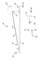
- the Fig. 1 shows a planar side view of a first embodiment of a support assembly, designated as a whole by 10, with two opposing support channel profiles 20, 30, rung parts 40 extending between the support channel profiles 20, 30, and solar modules 100 arranged on the support assembly 10, wherein the support assembly is fixed to a rafter 14 by means of clamping elements 16 and has a ridge side and an eaves side.
- the mounting situation of the support arrangement 10 is shown, in which solar modules are arranged on a roof structure, here in the form of a rafter 14.
- the upper ridge side is located at the second support gutter profile 30 shown on the right in the figure, while the lower eaves side is located at the first support gutter profile 20 shown on the left in the figure.
- a lattice part 40 extends between the mutually parallel support gutter profiles 20, 30 and receives a frame piece 102 of a solar module 100 extending parallel to the lattice part 40.
- the solar module 100 is of the support arrangement 10 between the two support channel profiles 20, 30. More precisely, it extends between the first longitudinal side 21 of the first support channel profile 20 and the second longitudinal side 32 of the second support channel profile 30.
- the solar module is fixed to the support arrangement 10 by the holding element 50 located on the first longitudinal side 21 of the first support channel profile 20 and the locking element 60 located on the second longitudinal side 32 of the second support channel profile 30. Furthermore, one can see in the Fig.
- FIGS. 2 to 8 show a chronological sequence of an assembly of a support arrangement 10 with first and second support channel profiles 20, 30, rung parts 40 extending between them, holding elements 50 and connecting elements 60.
- the Fig. 2a, 2b shows a planar side view of a second embodiment of a support arrangement 10 with two opposing support channel profiles 20, 30, rung parts 40 extending between the support channel profiles 20, 30, in which the support channel profiles 20, 30 have the same height ( Fig. 2a ) and an enlargement of an end region of a rung part on which a locking element 60 is arranged ( Fig. 2b ).
- the locking element 60 is inserted with a guide member 66 in the direction of the arrow into a guide 46 at the second end 42 of the rung part 40.
- the first end 41 of the rung part 40 is brought close to the first support channel profile 20 of the support arrangement in order to be arranged there.
- the Fig. 3a, 3b show a flat side view of the support arrangement of the Fig. 2a, 2b with locking element 60 arranged on one rung part end 42, wherein the rung part 40 is moved in the direction of the first support channel profile 20, at whose The holding element 50 is arranged on the first longitudinal side 21.
- the first support channel profile 20 shows a structure that is also valid for the second (identical) support channel profile, comprising a support channel profile base 23 and a support web 24 arranged thereon, projecting from the support channel profile base 23 and having a transverse web 26.
- a support element 28, 29 projects from the support channel profile base to each longitudinal side 21, 22 to support rung parts 40; the support elements 28, 29 are aligned essentially parallel to the support web 24.
- the holding element 50 arranged on the support channel profile 20 in the Fig. 3b forms a receptacle 51 which is approximately C-shaped in cross-section and parallel to the support web 24.
- the holding element 50 is provided so as to be displaceable along the first longitudinal side 21 of the support channel profile 20 or the support web 24, wherein it engages with a hook-like projection 53 on the side of the receiving base 52 facing the longitudinal side into a hinge opening 54, whereby the holding element 50 is designed to be pivotable against the support web 24.
- the holding element 50 is supported by a support web 55 on the first longitudinal side 21 of the first support channel profile 20 or the support web 24.
- the free end 57 of the holding element 50 received in the engagement section 48 of the rung part 40 and a locking arm 58 are arranged, the free end of which is designed to lock with a locking projection 59 on the support web 24 and thus to fix the holding element 50 and thus later the solar module 100.
- the Fig. 4a, 4b show a planar side view of the support arrangement 10 of the Fig. 3a, 3b in which the end region 41 of the rung part 40 facing the first support channel profile 20 receives the free end 57 of the holding element 50 and the other, second end 42 of the rung part 40 is pivoted in the direction of the second support channel profile 30.
- the features of the second Support channel profiles are provided with the reference numbers assigned to them, however, the second support channel profile 30 can be seen in the view of the Fig.4 to the right, a first support channel profile 20 is formed again, and further to the right, a second support channel profile 30 is arranged. The same applies to the continuation of the support arrangement to the left side for the viewer.
- the Fig. 5a, 5b show a planar side view of the support arrangement 10 of the Fig. 4a, 4b in which the second end region 42 of the rung part 40 facing the second support channel profile 30 is pivoted to the respective support channel profile 30, shortly before the end region 42 of the rung part 40 comes to rest on the support element 38 of the second support channel profile 30.
- the locking element 60 arranged thereon which is inserted into the guide 46 with the guide member 66, is brought with its holding member 62 and its locking member 64 close to the second longitudinal side 32 of the second support channel profile 30 in such a way that the end of the locking member 64 engages behind a cross-sectional change 65 of the support web 34.
- the directional arrows here indicate that the end region 42 of the rung part 40 is moved downwards in the direction of the support element 38 and the locking element 60 is moved to the right in the direction of the support web 34. It can be seen from the locking member 60 that the holding member 62 and the locking member 64 are collinear with one another and the guide member 66 points in the direction of the rung part 40.
- the Fig. 6a, 6b show a planar side view of the support arrangement 10 of the Fig. 5a, 5b in which the rung part 40 extends between the support channel profiles 20, 30 and in which a solar module 100 is arranged on the support arrangement 10, wherein initially an end region of the solar module 100 is arranged near the second longitudinal side 32 of the second support channel profile 30 and the second end region 42 of the rung part 40.
- the second The end region of the rung part 40 sits on the support element 38 on the second longitudinal side 32 of the second support channel profile 30, while the locking element 60 rests with its holding member 62 on the second longitudinal side 32 of the second support channel profile and the free end of the locking member 64 is supported on the cross-sectional change 65 of the support web 34.
- the Fig. 7a, 7b show a planar side view of the support arrangement 10 of the Fig. 6a, 6b in which the solar module 100 with its frame piece 102 is accommodated in the rung part 40, and the front end of the solar module 100 facing the first support channel profile 20 is moved towards the first longitudinal side 21 of the first support channel profile 20 by sliding, which is indicated by the directional arrow of the Fig. 7b is indicated.
- this end of the solar module engages under the receiving leg 56b arranged at the upper end of the holder 51 facing away from the support channel profile base 23 and can no longer deflect away from the support channel profile base 23.
- FIG. 8a, 8b show a planar side view of the support arrangement 10 of the Fig. 7a, 7b in which the solar module 100 is fixed to the support arrangement 10 by locking the locking element 60 on the second longitudinal side 32 of the second support channel profile 30.
- the locking element which is guided on its guide member 66 in the guide 46 of the rung part 40, is moved in the direction of the rung part 40, whereby its locking member 64 is pressed in front of the cross-sectional change 65 on the one hand due to its sufficient flexibility, and on the other hand due to its sufficient rigidity and the shape of the cross-sectional change 65 of the support web 34 as a recess 68 on the second longitudinal side 32 of the Supporting channel profile 30 has no opportunity to engage with it again.
- the cross-sectional change 65 of the supporting web 34 here consists in the fact that in its section facing the supporting channel profile base 33, the cavity 35 is formed, which has a quadrangular edge in cross-section, in one end region of which the aforementioned recess 68 is formed.
- the solar module 100 is secured here by a transverse web 36 pointing transversely away from the supporting web 34, which is arranged at the free end of the supporting web 34 and projects therefrom and engages over the end regions of adjacently arranged solar modules 100 facing this longitudinal side 32 at their surface.
- a deflector piece 67 is formed on each side, starting at the end facing the other members 62, 64, which extends so far toward the free end of the locking piece that, regardless of the movement path of the locking member 66, no side region of the guide member 66 is ever exposed without a deflector piece 67. In this way, it can be prevented that moisture to be discharged from the solar modules 100 can escape from the cross section of the rung parts 40.
- Fig. 9a, 9b shows a perspective view from above of a section of a support arrangement 10 without solar modules 100 and an enlargement of the frontal area of a basically arbitrary first or second support channel profile 20, 30 with its two longitudinal sides 21, 22, 31, 32.
- Fig. 9a that the support arrangement 10 can be continued both longitudinally and transversely.
- a narrower rung part can be provided, into which only one frame piece of a solar module 100 engages, since only one frame piece is to be held here.
- the rung parts 40 of the support arrangement 10 are arranged exactly where two solar modules 100 are adjacent to each other with their longitudinal sides, so that the frame pieces of both solar modules can jointly engage in the cross section of the associated rung part.
- the solar modules form 100 surfaces of the same plane.
- first support channel profile 20 again form a second support channel profile 30 with respect to the unlabeled rear part of the illustration, and the rear support channel profile a support channel profile 20.
- the second support gutter profile 30 would face the ridge and the first support gutter profile 20 would face the eaves.
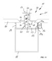
- FIG. 11 a planar side view of an embodiment of the support arrangement 10, in which a support gutter profile 20 (without solar modules 100) has been connected to a purlin 18 of a roof structure, for example by welding.
- the support gutter profile base 23 spans the width of the purlin 18, which supports the support gutter profile base 23 and thus the support gutter profile 20 itself.
- a cable duct 12 is suspended from its recesses 29a, 29b facing away from the support web 24, which serves to electrify the module field. This cable duct can also be suspended on the opposite side of the support web.
- a guide projection 27 facing away from the support gutter profile base 23 can be seen.
- the support arrangement 10 can be moved by means of a travel system (not shown) which is guided on the guide projections 27, 37.
- a system which is intended and configured to support solar modules 100 at a distance from a surface covered by these solar modules 100, is provided with at least two mutually parallel support channel profiles 20, 30, each provided with a support web 24, 34 and on this with a first longitudinal side 21, 31 and a second longitudinal side 22, 32, wherein between the support webs 24, 34 of the at least two support channel profiles 10, 20 a plurality of solar modules 100 are arranged, which in the position of use lie next to one another along their longitudinal sides.
- the support arrangement 10 has a plurality of rung parts 40, which each extend between the at least two parallel support channel profiles 20, 30 and at least indirectly support frame pieces 102 of two adjacent solar modules 100, and a plurality of holding elements 50, which are detachably connected and supported by a first longitudinal side 21 of the support web 24 of a first of the at least two support channel profiles 20, wherein in each case an associated rung part 40 receives a free end 57 of a holding element 50 at its first end 41 in an engagement section.
Landscapes
- Engineering & Computer Science (AREA)
- Architecture (AREA)
- Structural Engineering (AREA)
- Civil Engineering (AREA)
- Chemical & Material Sciences (AREA)
- Thermal Sciences (AREA)
- Physics & Mathematics (AREA)
- Combustion & Propulsion (AREA)
- Mechanical Engineering (AREA)
- General Engineering & Computer Science (AREA)
- Sustainable Energy (AREA)
- Sustainable Development (AREA)
- Life Sciences & Earth Sciences (AREA)
- Photovoltaic Devices (AREA)
- Roof Covering Using Slabs Or Stiff Sheets (AREA)
Claims (15)
- Dispositif de support (10) qui est prévu et aménagé pour soutenir à distance des modules solaires (100) par rapport à une surface recouverte par ces modules solaires (100),avec au moins deux profilés de support en forme de gouttière (20, 30) parallèles entre eux, qui sont chacun pourvus d'au moins une traverse de support (24, 34), qui présente de son côté un premier côté longitudinal (21, 31) et un deuxième côté longitudinal (22, 32), une pluralité de modules solaires (100) étant disposés entre les barrettes porteuses (24, 34) des au moins deux profilés de rainure de support (20, 30), lesquels modules solaires sont juxtaposés dans la position d'utilisation le long de leurs côtés longitudinaux,avec une pluralité d'éléments d'entretoise (40) qui s'étendent chacun entre les au moins deux profilés de support parallèles (20, 30) et supportent au moins indirectement les éléments de cadre (102) de deux modules solaires (100) adjacents,caractérisé en ce que le dispositif de support (10) comprend en outre :une pluralité d'éléments de maintien (50), qui sont maintenus et soutenus de manière amovible par un premier côté longitudinal (21) de la nervure porteuse (24) d'un premier profilé de rail porteur (20) des au moins deux profilés de rail porteur (20, 30), une pièce de meneau (40) associée recevant à son extrémité (41) une extrémité libre (57) d'un élément de maintien (50) dans une section d'engagement ; etune pluralité d'éléments de verrouillage (60), qui peuvent être disposés ou sont disposés chacun à une deuxième extrémité (42) de l'une des parties de meneau (40), laquelle est tournée vers le deuxième côté longitudinal (32) d'une âme porteuse (34) d'un deuxième profilé de rainure porteuse (30) des au moins deux profilés de rainure porteuse (20, 30), chacun des éléments de verrouillage (60) étant conçu pour pouvoir être déplacé dans un guidage (46) le long de l'extension longitudinale de la deuxième extrémité ( 42) de la partie de traverse respective (40) dans un guidage (46) le long de son extension longitudinale et d'être relié au deuxième côté longitudinal (32) de l'âme porteuse (34) du deuxième profilé de rainure de support (30) par coulissement le long du guidage (46) de telle sorte de sorte que les extrémités des modules solaires (100) tournées vers le deuxième profilé porteur en forme de gouttière (30) sont maintenues et verrouillées avec l'extrémité (42) des traverses (40) sur l'âme porteuse (32) du deuxième profilé porteur en forme de gouttière (30).
- Dispositif de support selon la revendication 1, dans lequel le premier côté longitudinal (21, 31) et le deuxième côté longitudinal (31, 32) des nervures de support (24, 34) des au moins deux profilés de rainure de support (20, 30) diffèrent et les au moins deux profilés de rainure de support (20, 30) sont chacun pourvus d'un fond (23, 33) dont dépasse la nervure porteuse (24, 34) correspondante.
- Dispositif de support selon la revendication 1 ou 2, dans lequel les côtés longitudinaux (21, 22, 31, 32) des profilés porteurs en forme de gouttière sont espacés les uns des autres et sont reliés à leurs extrémités supérieure et inférieure par le fond (23, 33) du profilé porteur en forme de gouttière et par un élément de toit (27, 37), ce qui permet de former un espace creux (25, 35) au niveau de chaque profilé de gouttière porteur (20, 30).
- Dispositif de support selon l'une des revendications 2 ou 3, le fond (23, 33) des au moins deux profilés de rainure de support (20, 30) présentant un élément de support (28, 29, 38, 39) pour chaque côté longitudinal (21, 22, 31, 32) de l'âme porteuse respective (20, 30),qui dépasse du fond (23, 33) et dont l'extrémité libre porte une zone d'extrémité (4, 42) d'un élément de meneau (40).
- Dispositif de support Dispositif de support selon l'une des revendications précédentes, dans laquelle les éléments d'échelons (40) présentent une longueur prédéfinie et une section transversale ouverte vers le haut, en particulier une section transversale en forme de C ou de U, dans laquelle s'engagent respectivement les pièces de cadre (102) des modules solaires (100) voisins..
- Dispositif de support selon l'une des revendications précédentes, dans laquelle au moins une pièce d'écartement (44) est associée à chaque partie de barreau (40), laquelle est logée de manière amovible dans la section transversale de la partie de barreau (40) et forme un support pour les pièces de cadre (102) des modules solaires (100).
- Dispositif de support selon l'une des revendications précédentes, dans lequel chaque élément de maintien (50) présente un logement (51) de section transversale approximativement en forme de C avec un fond de logement (51) disposé parallèlement à l'âme porteuse (24, 34), qui entoure les zones d'angle de deux modules solaires (100) voisins d'au moins deux côtés.
- Dispositif de support selon l'une des revendications précédentes, dans lequel chacun des éléments de retenue (50) est prévu de manière à pouvoir coulisser le long du premier côté longitudinal (21, 31) du profilé de rainure de support (20), une saillie en forme de crochet (53) sur le côté du fond de réception (52) tourné vers le premier côté longitudinal (21) s'engageant dans une ouverture de charnière (54) sur le premier côté longitudinal (21), l'élément de retenue (50) pouvant ainsi pivoter contre l'âme porteuse (24, 34).
- Dispositif de support selon l'une des revendications précédentes, dans lequel l'extrémité libre (57) de l'élément de retenue (50) logée dans la partie d'engagement de la traverse (40) et un bras d'encliquetage (58) dont l'extrémité libre est conçue pour s'enclencher avec une saillie d'enclenchement (59) sur la traverse porteuse (24) et fixer ainsi l'élément de maintien (50).
- Dispositif de support selon la revendication 9, dans lequel une traverse (26) est disposée sur les profilés de support (20, 30) à l'extrémité libre de l'âme porteuse (24), laquelle traverse dépasse du deuxième côté longitudinal (32) et recouvre les zones d'extrémité des modules solaires (100) disposés côte à côte et tournées vers ce côté longitudinal (32).
- Dispositif de support selon l'une des revendications précédentes, dans lequel les éléments de verrouillage (60) sont prévus en plusieurs parties avec un élément de retenue (62), un élément de verrouillage (64) et un élément de guidage (66), l'élément de maintien (62) et l'élément de verrouillage (64) s'étendant essentiellement parallèlement l'un à l'autre et au deuxième côté longitudinal (32) de la traverse porteuse (34), tandis que l'élément de guidage (66) fait saillie transversalement à ceux-ci en direction de la partie meneau (40).
- Dispositif de support selon la revendication 11, dans lequel l'élément de verrouillage (64) de l'élément de verrouillage (60) est agencé de manière à pendant le verrouillage de l'élément de verrouillage (60), en se déplaçant le long de la partie de meneau (40) associée, de surmonter avec son extrémité libre une modification de section (65) du deuxième côté longitudinal (32), qui bloque un mouvement inverse ultérieur de l'élément de verrouillage (60).
- Dispositif de support selon l'une des revendications précédentes, les profilés de support (20, 30) pouvant être reliés ou étant reliés à un élément structurel d'une structure de toit.
- Dispositif de support selon l'une des revendications précédentes, le dispositif porteur (10) présentant un nombre n de profilés porteurs en forme de gouttière (20, 30) parallèles les uns aux autres, n étant un nombre naturel ≥ 2, et/ou le dispositif porteur (10) pouvant être prolongé ou étant prolongé dans le sens de l'extension des profilés porteurs en forme de gouttière (20, 30) par la dispositif de plusieurs profilés porteurs en forme de gouttière (20, 30) les uns derrière les autres.
- Dispositif de support selon l'une des revendications précédentes, dans lequel les profilés de support (20, 30) sont prévus pour disposer les modules solaires (100) du dispositif porteur (10) les uns par rapport aux autres de telle sorte que les modules solaires (100) forment des portions de surface respectivement du même plan ou de la même surface courbe.
Priority Applications (3)
| Application Number | Priority Date | Filing Date | Title |
|---|---|---|---|
| EP21216315.8A EP4203300B1 (fr) | 2021-12-21 | 2021-12-21 | Agencement de support et de fixation pour modules solaires |
| PCT/EP2022/087242 WO2023118299A1 (fr) | 2021-12-21 | 2022-12-21 | Ensemble de support et de fixation pour modules solaires |
| US18/721,950 US20240396489A1 (en) | 2021-12-21 | 2022-12-21 | Carrying and fastening arrangement for solar modules |
Applications Claiming Priority (1)
| Application Number | Priority Date | Filing Date | Title |
|---|---|---|---|
| EP21216315.8A EP4203300B1 (fr) | 2021-12-21 | 2021-12-21 | Agencement de support et de fixation pour modules solaires |
Publications (3)
| Publication Number | Publication Date |
|---|---|
| EP4203300A1 EP4203300A1 (fr) | 2023-06-28 |
| EP4203300C0 EP4203300C0 (fr) | 2025-04-23 |
| EP4203300B1 true EP4203300B1 (fr) | 2025-04-23 |
Family
ID=79021673
Family Applications (1)
| Application Number | Title | Priority Date | Filing Date |
|---|---|---|---|
| EP21216315.8A Active EP4203300B1 (fr) | 2021-12-21 | 2021-12-21 | Agencement de support et de fixation pour modules solaires |
Country Status (3)
| Country | Link |
|---|---|
| US (1) | US20240396489A1 (fr) |
| EP (1) | EP4203300B1 (fr) |
| WO (1) | WO2023118299A1 (fr) |
Family Cites Families (39)
| Publication number | Priority date | Publication date | Assignee | Title |
|---|---|---|---|---|
| US3867045A (en) * | 1974-03-25 | 1975-02-18 | Amax Aluminum Company Inc | Tube connector |
| GB2000860B (en) * | 1977-07-06 | 1982-08-04 | Showa Aluminium Co Ltd | Solar collector |
| US4372292A (en) * | 1981-04-14 | 1983-02-08 | Ort Sterling L | Method and apparatus for construction of a solar collector |
| JPH0833054B2 (ja) * | 1989-03-30 | 1996-03-29 | 株式会社平井技研 | 屋根装置 |
| EP0599497A1 (fr) * | 1992-11-19 | 1994-06-01 | Hirai Engineering Corporation | Système de toit utilisant des cellules solaires |
| NL1006490C2 (nl) * | 1997-07-04 | 1999-01-05 | Alcoa Compri Aluminium | Frame voor schuin te plaatsen panelen, in het bijzonder zonnepanelen, alsmede uitbreidingsset daarvoor. |
| US6105317A (en) * | 1997-09-24 | 2000-08-22 | Matsushita Electric Works, Ltd. | Mounting system for installing an array of solar battery modules of a panel-like configuration on a roof |
| WO2002041407A1 (fr) * | 2000-11-16 | 2002-05-23 | Kaneka Corporation | Module de batterie solaire, systeme de production d'energie photovoltaique, bloc de support supportant ce module de batterie solaire, et procede d'installation d'un systeme de production d'energie photovoltaique |
| DE10161190A1 (de) * | 2001-12-13 | 2003-06-18 | Fischer Artur Werke Gmbh | Knotenverbinder zum Befestigen von Montageschienen |
| US6799398B1 (en) * | 2002-06-18 | 2004-10-05 | Skytech Systems, Inc. | Modular system for securing flat panels to a curved support structure |
| US7406800B2 (en) * | 2004-05-18 | 2008-08-05 | Andalay Solar, Inc. | Mounting system for a solar panel |
| DE102007033323B4 (de) * | 2007-07-16 | 2014-03-06 | Fath Gmbh | Befestigungseinrichtung für an einem Gestellaufbau anzuordnende flächige Bauteile, insbesondere Solarmodule |
| US7883288B2 (en) * | 2007-09-28 | 2011-02-08 | Minnis & Samson Pty, Ltd. | Connector |
| JP2010045346A (ja) * | 2008-07-24 | 2010-02-25 | Bp Corp North America Inc | 調整可能な連結式ソーラーモジュールおよび設置方法 |
| EP2187146B1 (fr) * | 2008-11-14 | 2019-01-02 | Böcherer, Hans | Agencement de support |
| ES2356763B1 (es) * | 2009-04-01 | 2012-03-20 | Producciones Mitjavila, S.A. | Sistema modular de fijación de paneles solares a una cubierta provisto de medios para canalizar el agua. |
| DE202010000293U1 (de) * | 2009-10-09 | 2010-05-20 | Galaxy-Energy Gmbh | Solardachanordnung |
| SG172493A1 (en) * | 2009-12-11 | 2011-07-28 | Grenzone Pte Ltd | Integrated photovoltaic roof assembly |
| ES1071742Y (es) * | 2010-02-10 | 2010-06-25 | Producciones Mitjavila Sa | Estructura de fijacion de paneles solares |
| FR2959800A1 (fr) * | 2010-05-05 | 2011-11-11 | S Q P | Installation pour le montage de panneaux photovoltaiques integres a un batiment |
| FR2960047A1 (fr) * | 2010-05-14 | 2011-11-18 | Fonroche En | Dispositif d'etancheite d'une paroi formee d'une pluralite de panneaux solaires juxtaposes |
| FR2960607B1 (fr) * | 2010-05-28 | 2017-10-13 | Ateliers Lr Etanco | Systeme de fixation d'un panneau sur un revetement |
| US8191321B2 (en) * | 2010-06-10 | 2012-06-05 | Mcclellan Vncent Jack | Building integrated solar array support structure device, system, and method |
| EP2598812A2 (fr) * | 2010-07-26 | 2013-06-05 | Efraim Molek | Mécanisme de verrouillage pour panneaux |
| US8590222B2 (en) * | 2010-10-05 | 2013-11-26 | Alexander Koller | Support arrangement |
| KR101188176B1 (ko) * | 2011-01-07 | 2012-10-05 | (주)썬트랙 | 샌드위치 패널형의 지붕 설치용 태양광 발전 장치 |
| US9157665B2 (en) * | 2011-03-15 | 2015-10-13 | Richard William Erickson | Unitized photovoltaic assembly |
| DE202012005162U1 (de) * | 2011-05-24 | 2012-07-11 | Solarmarkt Gmbh | Rahmenteil für plattenförmige Funktionselemente und Abdeckungs-System gebildet aus einer Vielzahl derartiger Funktionselemente |
| US8387319B1 (en) * | 2011-09-02 | 2013-03-05 | Opsun Systems Inc. | Solar panel securing assembly for sheet metal sloping roofs |
| EP2568231A1 (fr) * | 2011-09-07 | 2013-03-13 | Photowatt International | Dispositif de fixation d'un module solaire photovoltaïque sur un support |
| US9647157B2 (en) * | 2011-12-13 | 2017-05-09 | Solarcity Corporation | Discrete attachment point apparatus and system for photovoltaic arrays |
| WO2014126226A1 (fr) * | 2013-02-18 | 2014-08-21 | 京セラ株式会社 | Dispositif de cellules solaires |
| DE102014007971A1 (de) * | 2014-06-04 | 2015-12-17 | Schletter Gmbh | Vorrichtung zum Halten von Solarmodulrahmen |
| US9455662B2 (en) * | 2015-01-27 | 2016-09-27 | Ironridge, Inc. | Assembly for locking and grounding solar panel modules to mounting components |
| KR102548355B1 (ko) * | 2021-05-03 | 2023-06-28 | (주)에이비엠 | 건물 일체형 태양광 발전지붕 |
| US12398564B2 (en) * | 2021-08-16 | 2025-08-26 | Certainteed Llc | Roofing system and method of installation |
| TWI836342B (zh) * | 2022-01-28 | 2024-03-21 | 虹星再生能源股份有限公司 | 具導水功能之太陽能板支架及其固定裝置 |
| US20240128923A1 (en) * | 2022-10-17 | 2024-04-18 | Kevin Stapleton | Panel mounting bracket with quick release clip and related methods |
| US12119780B1 (en) * | 2024-04-19 | 2024-10-15 | Roosters Unlimited OÜ | Mounting bracket system for solar panels and solar panel comprising the same |
-
2021
- 2021-12-21 EP EP21216315.8A patent/EP4203300B1/fr active Active
-
2022
- 2022-12-21 US US18/721,950 patent/US20240396489A1/en active Pending
- 2022-12-21 WO PCT/EP2022/087242 patent/WO2023118299A1/fr not_active Ceased
Also Published As
| Publication number | Publication date |
|---|---|
| EP4203300C0 (fr) | 2025-04-23 |
| US20240396489A1 (en) | 2024-11-28 |
| EP4203300A1 (fr) | 2023-06-28 |
| WO2023118299A1 (fr) | 2023-06-29 |
Similar Documents
| Publication | Publication Date | Title |
|---|---|---|
| EP2003405B1 (fr) | Dispositif de fixation pour des composants plats installés sur un bâti, en particulier pour des modules solaires | |
| DE2829281C2 (de) | Als Sonnenkollektor ausgebildetes Dach | |
| EP2261577A2 (fr) | Bâti porteur pour une installation photovoltaïque en terrain libre | |
| EP3715561B1 (fr) | Système de toiture et module de support associé | |
| EP2017554A2 (fr) | Dispositif de fixation pour des composants plats installés sur un montage de structure, en particulier des modules solaires | |
| EP2186964B1 (fr) | Recouvrement avec au moins deux tôles métalliques entre des profilés et installation solaire sur ce recouvrement | |
| AT524775B1 (fr) | ||
| DE69908804T2 (de) | Gebäude mit trägern und einer dachrinne, dachrinne und träger zur verwendung darin | |
| DE3346585A1 (de) | Ueberdachung mit mindestens einem verschiebbaren dachteil | |
| DE102005032859B3 (de) | Befestigungssystem für Solarmodule | |
| CH717416B1 (de) | Tragkonstruktion für vertikal angeordnete Photovoltaik-Module. | |
| EP2378563A2 (fr) | Système de montage pour module solaire | |
| DE102009037978B4 (de) | Traggerüst für eine Photovoltaik-Freiflächenanlage sowie Verfahren zur Montage eines Traggerüsts | |
| DE202021104820U1 (de) | Befestigungsvorrichtung zur Befestigung eines einen Teil eines Daches eines Gebäudes bildenden Photovoltaikmoduls am Gebäude und Verbindungsvorrichtungen zur Verbindung solcher Photovoltaikmodule miteinander | |
| DE10136037A1 (de) | Dachintegriertes Solarmodulsystem | |
| DE20110896U1 (de) | Auflageleiste für Fassadenelemente und Anordnung von Fassadenelementen | |
| EP4203300A1 (fr) | Agencement de support et de fixation pour modules solaires | |
| DE20014660U1 (de) | Wand- oder Dachfläche | |
| AT517212B1 (de) | Montagesystem für Solarmodul | |
| DE2404954C3 (de) | Treibhaus | |
| WO2012163335A2 (fr) | Agencement de modules photovoltaïques sans cadre sur une structure de toit | |
| EP4163452B1 (fr) | Structure de toit incliné | |
| AT505553A4 (de) | Dachziegel | |
| EP4603653B1 (fr) | Construction de toit pour jardin d'hiver, jardin d'hiver et toit de terrasse | |
| EP2896909B1 (fr) | Système de montage en toiture de modules solaires |
Legal Events
| Date | Code | Title | Description |
|---|---|---|---|
| PUAI | Public reference made under article 153(3) epc to a published international application that has entered the european phase |
Free format text: ORIGINAL CODE: 0009012 |
|
| STAA | Information on the status of an ep patent application or granted ep patent |
Free format text: STATUS: THE APPLICATION HAS BEEN PUBLISHED |
|
| AK | Designated contracting states |
Kind code of ref document: A1 Designated state(s): AL AT BE BG CH CY CZ DE DK EE ES FI FR GB GR HR HU IE IS IT LI LT LU LV MC MK MT NL NO PL PT RO RS SE SI SK SM TR |
|
| STAA | Information on the status of an ep patent application or granted ep patent |
Free format text: STATUS: REQUEST FOR EXAMINATION WAS MADE |
|
| 17P | Request for examination filed |
Effective date: 20231222 |
|
| RBV | Designated contracting states (corrected) |
Designated state(s): AL AT BE BG CH CY CZ DE DK EE ES FI FR GB GR HR HU IE IS IT LI LT LU LV MC MK MT NL NO PL PT RO RS SE SI SK SM TR |
|
| GRAP | Despatch of communication of intention to grant a patent |
Free format text: ORIGINAL CODE: EPIDOSNIGR1 |
|
| STAA | Information on the status of an ep patent application or granted ep patent |
Free format text: STATUS: GRANT OF PATENT IS INTENDED |
|
| INTG | Intention to grant announced |
Effective date: 20241118 |
|
| GRAS | Grant fee paid |
Free format text: ORIGINAL CODE: EPIDOSNIGR3 |
|
| GRAA | (expected) grant |
Free format text: ORIGINAL CODE: 0009210 |
|
| STAA | Information on the status of an ep patent application or granted ep patent |
Free format text: STATUS: THE PATENT HAS BEEN GRANTED |
|
| AK | Designated contracting states |
Kind code of ref document: B1 Designated state(s): AL AT BE BG CH CY CZ DE DK EE ES FI FR GB GR HR HU IE IS IT LI LT LU LV MC MK MT NL NO PL PT RO RS SE SI SK SM TR |
|
| REG | Reference to a national code |
Ref country code: GB Ref legal event code: FG4D Free format text: NOT ENGLISH |
|
| REG | Reference to a national code |
Ref country code: CH Ref legal event code: EP |
|
| REG | Reference to a national code |
Ref country code: DE Ref legal event code: R096 Ref document number: 502021007281 Country of ref document: DE |
|
| REG | Reference to a national code |
Ref country code: IE Ref legal event code: FG4D Free format text: LANGUAGE OF EP DOCUMENT: GERMAN |
|
| U01 | Request for unitary effect filed |
Effective date: 20250523 |
|
| U07 | Unitary effect registered |
Designated state(s): AT BE BG DE DK EE FI FR IT LT LU LV MT NL PT RO SE SI Effective date: 20250602 |
|
| PG25 | Lapsed in a contracting state [announced via postgrant information from national office to epo] |
Ref country code: ES Free format text: LAPSE BECAUSE OF FAILURE TO SUBMIT A TRANSLATION OF THE DESCRIPTION OR TO PAY THE FEE WITHIN THE PRESCRIBED TIME-LIMIT Effective date: 20250423 |
|
| PG25 | Lapsed in a contracting state [announced via postgrant information from national office to epo] |
Ref country code: GR Free format text: LAPSE BECAUSE OF FAILURE TO SUBMIT A TRANSLATION OF THE DESCRIPTION OR TO PAY THE FEE WITHIN THE PRESCRIBED TIME-LIMIT Effective date: 20250724 Ref country code: NO Free format text: LAPSE BECAUSE OF FAILURE TO SUBMIT A TRANSLATION OF THE DESCRIPTION OR TO PAY THE FEE WITHIN THE PRESCRIBED TIME-LIMIT Effective date: 20250723 |
|
| PG25 | Lapsed in a contracting state [announced via postgrant information from national office to epo] |
Ref country code: PL Free format text: LAPSE BECAUSE OF FAILURE TO SUBMIT A TRANSLATION OF THE DESCRIPTION OR TO PAY THE FEE WITHIN THE PRESCRIBED TIME-LIMIT Effective date: 20250423 |
|
| PG25 | Lapsed in a contracting state [announced via postgrant information from national office to epo] |
Ref country code: HR Free format text: LAPSE BECAUSE OF FAILURE TO SUBMIT A TRANSLATION OF THE DESCRIPTION OR TO PAY THE FEE WITHIN THE PRESCRIBED TIME-LIMIT Effective date: 20250423 |
|
| PG25 | Lapsed in a contracting state [announced via postgrant information from national office to epo] |
Ref country code: RS Free format text: LAPSE BECAUSE OF FAILURE TO SUBMIT A TRANSLATION OF THE DESCRIPTION OR TO PAY THE FEE WITHIN THE PRESCRIBED TIME-LIMIT Effective date: 20250723 |
|
| PG25 | Lapsed in a contracting state [announced via postgrant information from national office to epo] |
Ref country code: IS Free format text: LAPSE BECAUSE OF FAILURE TO SUBMIT A TRANSLATION OF THE DESCRIPTION OR TO PAY THE FEE WITHIN THE PRESCRIBED TIME-LIMIT Effective date: 20250823 |
|
| PG25 | Lapsed in a contracting state [announced via postgrant information from national office to epo] |
Ref country code: SM Free format text: LAPSE BECAUSE OF FAILURE TO SUBMIT A TRANSLATION OF THE DESCRIPTION OR TO PAY THE FEE WITHIN THE PRESCRIBED TIME-LIMIT Effective date: 20250423 |
|
| PG25 | Lapsed in a contracting state [announced via postgrant information from national office to epo] |
Ref country code: CZ Free format text: LAPSE BECAUSE OF FAILURE TO SUBMIT A TRANSLATION OF THE DESCRIPTION OR TO PAY THE FEE WITHIN THE PRESCRIBED TIME-LIMIT Effective date: 20250423 |
|
| PG25 | Lapsed in a contracting state [announced via postgrant information from national office to epo] |
Ref country code: SK Free format text: LAPSE BECAUSE OF FAILURE TO SUBMIT A TRANSLATION OF THE DESCRIPTION OR TO PAY THE FEE WITHIN THE PRESCRIBED TIME-LIMIT Effective date: 20250423 |
|
| U20 | Renewal fee for the european patent with unitary effect paid |
Year of fee payment: 5 Effective date: 20260102 |
|
| PLBE | No opposition filed within time limit |
Free format text: ORIGINAL CODE: 0009261 |
|
| STAA | Information on the status of an ep patent application or granted ep patent |
Free format text: STATUS: NO OPPOSITION FILED WITHIN TIME LIMIT |
|
| REG | Reference to a national code |
Ref country code: CH Ref legal event code: L10 Free format text: ST27 STATUS EVENT CODE: U-0-0-L10-L00 (AS PROVIDED BY THE NATIONAL OFFICE) Effective date: 20260304 |
|
| 26N | No opposition filed |
Effective date: 20260126 |