EP4203473B1 - Procédé, dispositif de traitement d'image permettant de diviser un réseau de pixels en tranches et en tuiles et système de codage des tranches et des tuiles en un flux vidéo - Google Patents
Procédé, dispositif de traitement d'image permettant de diviser un réseau de pixels en tranches et en tuiles et système de codage des tranches et des tuiles en un flux vidéo Download PDFInfo
- Publication number
- EP4203473B1 EP4203473B1 EP21216704.3A EP21216704A EP4203473B1 EP 4203473 B1 EP4203473 B1 EP 4203473B1 EP 21216704 A EP21216704 A EP 21216704A EP 4203473 B1 EP4203473 B1 EP 4203473B1
- Authority
- EP
- European Patent Office
- Prior art keywords
- tiles
- subset
- pixels
- slices
- slice
- Prior art date
- Legal status (The legal status is an assumption and is not a legal conclusion. Google has not performed a legal analysis and makes no representation as to the accuracy of the status listed.)
- Active
Links
Images


Classifications
-
- H—ELECTRICITY
- H04—ELECTRIC COMMUNICATION TECHNIQUE
- H04N—PICTORIAL COMMUNICATION, e.g. TELEVISION
- H04N19/00—Methods or arrangements for coding, decoding, compressing or decompressing digital video signals
- H04N19/10—Methods or arrangements for coding, decoding, compressing or decompressing digital video signals using adaptive coding
- H04N19/102—Methods or arrangements for coding, decoding, compressing or decompressing digital video signals using adaptive coding characterised by the element, parameter or selection affected or controlled by the adaptive coding
- H04N19/119—Adaptive subdivision aspects, e.g. subdivision of a picture into rectangular or non-rectangular coding blocks
-
- H—ELECTRICITY
- H04—ELECTRIC COMMUNICATION TECHNIQUE
- H04N—PICTORIAL COMMUNICATION, e.g. TELEVISION
- H04N19/00—Methods or arrangements for coding, decoding, compressing or decompressing digital video signals
- H04N19/10—Methods or arrangements for coding, decoding, compressing or decompressing digital video signals using adaptive coding
- H04N19/169—Methods or arrangements for coding, decoding, compressing or decompressing digital video signals using adaptive coding characterised by the coding unit, i.e. the structural portion or semantic portion of the video signal being the object or the subject of the adaptive coding
- H04N19/17—Methods or arrangements for coding, decoding, compressing or decompressing digital video signals using adaptive coding characterised by the coding unit, i.e. the structural portion or semantic portion of the video signal being the object or the subject of the adaptive coding the unit being an image region, e.g. an object
- H04N19/174—Methods or arrangements for coding, decoding, compressing or decompressing digital video signals using adaptive coding characterised by the coding unit, i.e. the structural portion or semantic portion of the video signal being the object or the subject of the adaptive coding the unit being an image region, e.g. an object the region being a slice, e.g. a line of blocks or a group of blocks
-
- H—ELECTRICITY
- H04—ELECTRIC COMMUNICATION TECHNIQUE
- H04N—PICTORIAL COMMUNICATION, e.g. TELEVISION
- H04N19/00—Methods or arrangements for coding, decoding, compressing or decompressing digital video signals
- H04N19/10—Methods or arrangements for coding, decoding, compressing or decompressing digital video signals using adaptive coding
- H04N19/169—Methods or arrangements for coding, decoding, compressing or decompressing digital video signals using adaptive coding characterised by the coding unit, i.e. the structural portion or semantic portion of the video signal being the object or the subject of the adaptive coding
- H04N19/17—Methods or arrangements for coding, decoding, compressing or decompressing digital video signals using adaptive coding characterised by the coding unit, i.e. the structural portion or semantic portion of the video signal being the object or the subject of the adaptive coding the unit being an image region, e.g. an object
- H04N19/176—Methods or arrangements for coding, decoding, compressing or decompressing digital video signals using adaptive coding characterised by the coding unit, i.e. the structural portion or semantic portion of the video signal being the object or the subject of the adaptive coding the unit being an image region, e.g. an object the region being a block, e.g. a macroblock
-
- H—ELECTRICITY
- H04—ELECTRIC COMMUNICATION TECHNIQUE
- H04N—PICTORIAL COMMUNICATION, e.g. TELEVISION
- H04N19/00—Methods or arrangements for coding, decoding, compressing or decompressing digital video signals
- H04N19/10—Methods or arrangements for coding, decoding, compressing or decompressing digital video signals using adaptive coding
- H04N19/169—Methods or arrangements for coding, decoding, compressing or decompressing digital video signals using adaptive coding characterised by the coding unit, i.e. the structural portion or semantic portion of the video signal being the object or the subject of the adaptive coding
- H04N19/182—Methods or arrangements for coding, decoding, compressing or decompressing digital video signals using adaptive coding characterised by the coding unit, i.e. the structural portion or semantic portion of the video signal being the object or the subject of the adaptive coding the unit being a pixel
-
- H—ELECTRICITY
- H04—ELECTRIC COMMUNICATION TECHNIQUE
- H04N—PICTORIAL COMMUNICATION, e.g. TELEVISION
- H04N19/00—Methods or arrangements for coding, decoding, compressing or decompressing digital video signals
- H04N19/42—Methods or arrangements for coding, decoding, compressing or decompressing digital video signals characterised by implementation details or hardware specially adapted for video compression or decompression, e.g. dedicated software implementation
- H04N19/423—Methods or arrangements for coding, decoding, compressing or decompressing digital video signals characterised by implementation details or hardware specially adapted for video compression or decompression, e.g. dedicated software implementation characterised by memory arrangements
-
- H—ELECTRICITY
- H04—ELECTRIC COMMUNICATION TECHNIQUE
- H04N—PICTORIAL COMMUNICATION, e.g. TELEVISION
- H04N19/00—Methods or arrangements for coding, decoding, compressing or decompressing digital video signals
- H04N19/10—Methods or arrangements for coding, decoding, compressing or decompressing digital video signals using adaptive coding
- H04N19/134—Methods or arrangements for coding, decoding, compressing or decompressing digital video signals using adaptive coding characterised by the element, parameter or criterion affecting or controlling the adaptive coding
- H04N19/136—Incoming video signal characteristics or properties
-
- H—ELECTRICITY
- H04—ELECTRIC COMMUNICATION TECHNIQUE
- H04N—PICTORIAL COMMUNICATION, e.g. TELEVISION
- H04N19/00—Methods or arrangements for coding, decoding, compressing or decompressing digital video signals
- H04N19/42—Methods or arrangements for coding, decoding, compressing or decompressing digital video signals characterised by implementation details or hardware specially adapted for video compression or decompression, e.g. dedicated software implementation
- H04N19/436—Methods or arrangements for coding, decoding, compressing or decompressing digital video signals characterised by implementation details or hardware specially adapted for video compression or decompression, e.g. dedicated software implementation using parallelised computational arrangements
Definitions
- the present invention relates to image processing, and specifically to dividing an array of pixels into slices and tiles for encoding into an encoded video stream using a respective one of two separate image processing circuitries for encoding and buffering in relation to two subsets of pixels of the array of pixels.
- image frames Over time image frames have become larger e.g. due to higher resolution and larger image sensors.
- Other examples of large image frames are panoramic image frames constructed by stitching together image frames captured by multiple image sensors.
- each image frame may be divided into two or more image portions which are then processed in parallel in separate processing circuitries.
- the encoded image frame may also be divided into corresponding two or more image portions on a decoder side and the two or more image portions are then processed in parallel in separate processing circuitries.
- the separate processing circuitries can process the respective image portions independently to as large an extent as possible and share as little pixel data as possible since such sharing requires synchronization including transfer of pixel data between the processing circuitries which will slow down the processing and/or requires faster transfer of pixel data between the processing circuitries which increases the complexity and cost of the processing circuitries.
- An object of the present invention is to provide a method, an image processing device, and a system for dividing an array of pixels into slices and tiles for encoding into an encoded video stream using a respective one of two separate image processing circuitries for encoding and buffering in relation to two subsets of pixels of the array of pixels which overcome or mitigate issues in known methods, image processing devices and systems.
- a method for dividing an array of pixels into slices and tiles for encoding the array of pixels into an encoded video stream by means of a first encoder arranged in a first image processing circuitry and a second encoder arranged in a second image processing circuitry is provided. Pixels of the array of pixels are arranged at regular intervals along a vertical direction and a horizontal direction. Each slice is separated by a straight horizontal line over the full width of the array from respective adjacent slices and is be encoded without the need for access to image data relating to other slices and each tile is separated by a straight vertical line over the full height of a slice from respective adjacent tiles in the same slice and is encoded without the need for access to image data relating to other tiles.
- the array of pixels consists of a first subset of pixels having pixel data stored in a first buffer arranged in the first image processing circuitry and a second subset of pixels having pixel data stored in a second buffer arranged in the second image processing circuitry, wherein a first border between the first subset of pixels and the second subset of pixels is tilted at a tilt angle in relation to the array of pixels.
- the method comprises dividing the array of pixels into two or more slices, and dividing each slice into two or more tiles, wherein the two or more tiles of each slice consists of a first subset of tiles and a second subset of tiles, wherein the first subset of tiles and the second subset of tiles are disjunct and the first subset of tiles is to be encoded by the first encoder and the second subset of tiles is to be encoded by the second encoder.
- a second border between the first subset of tiles and the second subset of tiles is set at an offset along the horizontal direction between two adjacent slices of the two or more slices such that the second borders between the first subset of tiles and the second subset of tiles in two adjacent slices are not aligned along the horizontal direction, wherein the offset is based on the tilt angle such that the number of pixels to be encoded into the first subset of tiles of each slice that have pixel data stored in the second buffer plus the number of pixels to be encoded into the second subset of tiles of each slice that have pixel data stored in the first buffer is reduced in relation to not using an offset.
- the number of pixels to be encoded by the first encoder into the first subset of tiles of each slice that have pixel data stored in the second buffer plus the number of pixels to be encoded by the second encoder into the second subset of tiles of each slice that have pixel data stored in the first buffer is reduced in relation to not using an offset when the first border between the first subset of pixels and the second subset of pixels is tilted at a tilt angle in relation to the array of pixels.
- the amount of pixel data stored in the second buffer that needs be transferred to the first encoder and the amount of pixel data stored in the first buffer that needs be transferred to the second encoder is reduced in relation to not using an offset.
- a slice By a slice is meant a vertical separation - one above the other. Each slice may be encoded without the need for access to image data relating to other slices.
- tile By tile is meant a horizontal separation - one horizontally next to the other. Each tile may be encoded without the need for access to image data relating to other tiles.
- the first border tilting at a tilt angle here is meant that at least somewhere along the first border, the first border between the first and second subset of pixels does not extend along a column or row of pixels of the array of pixels such that pixels in a same column of pixels are located on different sides of the first border between the first and second subset of pixels and pixels in a same row of pixels are located on different sides of the first border between the first and second subset of pixels.
- An offset here is meant an offset along the length of the slices, i.e. such that the second borders between the first subset of tiles and the second subset of tiles in two adjacent slices are not aligned along the lengths of the slices.
- the offset between two adjacent slices is set taking into account the tilt angle such that different offsets will be set for different tilt angles.
- the offset may be set based on the tilt angle such that when subsequently encoding the first subset of tiles and the second subset of tiles into an encoded video stream by means of a first encoder and a second encoder, respectively, the number of pixels to be encoded into the first subset of tiles of each slice that have pixel data stored in the second buffer plus the number of pixels to be encoded into the second subset of tiles of each slice that have pixel data stored in the first buffer is minimized or at least kept as low as possible.
- the methodology for setting offset based on tilt angle may be iterative such that the sum of the number of pixels to be encoded into the first subset of tiles of each slice that have pixel data stored in the second buffer and the number of pixels to be encoded into the second subset of tiles of each slice that have pixel data stored in the first buffer is determined for different offsets and the offset is set to the offset resulting in the lowest sum.
- the tilt angle may be constant along the first border between the first subset of pixels and the second subset of pixels.
- the offset may then be set to be the same for each two adjacent slices of the two or more slices.
- the tilt angle may vary along the first border between the first subset of pixels and the second subset of pixels.
- the act of dividing the array of pixels into two or more slices may then comprise dividing the array of pixels into three or more slices, and the act of dividing each slice into two or more tiles may comprise, for each two adjacent slices of the three or more slices, setting a second border between the first subset of tiles and the second subset of tiles of each slice of the two adjacent slices at an offset, wherein the offset is based on a local tilt angle of the first border between the first subset of pixels and the second subset of pixels in the two adjacent slices.
- a local tilt angle is meant a measure of the tilt angle of the first border in the two adjacent slices for which the offset is to be set.
- the first border between the first subset of pixels and the second subset of pixels may be tilted at a constant but separate tilt angle in separate horizontal portions of the array of pixels.
- the act of dividing the array of pixels into three or more slices may then comprise dividing the array of pixels into four or more slices by dividing each separate horizontal portion of the array of pixels into two or more slices such that, for each two adjacent horizontal portions, a third border between the two adjacent horizontal portions is aligned with a fourth border between two adjacent slices. By aligning the fourth border between two adjacent slices with the third border between the two adjacent horizontal portions, the first border will have a constant tilt angle in the slices in each horizontal portion.
- the first border between the first subset of pixels and the second subset of pixels may be curved.
- the local tilt angle of the first border in the two adjacent slices may be determined as an average tilt angle in the two adjacent slices.
- Sizes of corresponding tiles of the two or more tiles of each of the two or more slices may be the same in each of the two or more slices. In other words, borders between tiles in the two or more slices may be horizontally aligned.
- the method may further comprise transferring pixel data to be encoded into pixels of the first subset of tiles of each slice having pixel data stored in the second buffer to the first encoder, encoding the first subset of tiles by means of the first encoder, transferring pixel data of pixels to be encoded into the second subset of tiles of each slice having pixel data stored in the first buffer to the second encoder, and encoding the second subset of tiles by means of the second encoder.
- a non-transitory computer-readable storage medium having stored thereon instructions for implementing the method according to the first aspect when executed by a device having processing capabilities.
- an image processing device for dividing an array of pixels into slices and tiles for encoding the array of pixels into an encoded video stream by means of a first encoder arranged in a first image processing circuitry and a second encoder arranged in a second image processing circuitry. Pixels of the array of pixels are arranged at regular intervals along a vertical direction and a horizontal direction. Each slice is separated by a straight horizontal line over the full width of the array from respective adjacent slices and is encoded without the need for access to image data relating to other slices and each tile is separated by a straight vertical line over the full height of a slice from respective adjacent tiles in the same slice and is encoded without the need for access to image data relating to other tiles.
- the array of pixels consists of a first subset of pixels having pixel data stored in a first buffer arranged in the first image processing circuitry and a second subset of pixels having pixel data stored in a second buffer arranged in the second image processing circuitry, wherein a first border between the first subset of pixels and the second subset of pixels is tilted at a tilt angle in relation to the array of pixels.
- the device comprises circuitry configured to execute a first dividing function configured to divide the array of pixels into two or more slices, and a second dividing function configured to divide each slice into two or more tiles, wherein the two or more tiles of each slice consists of a first subset of tiles and a second subset of tiles, wherein the first subset of tiles and the second subset of tiles are disjunct and the first subset of tiles is to be encoded by the first encoder and the second subset of tiles is to be encoded by the second encoder.
- the second dividing function is further configured to set a second border between the first subset of tiles and the second subset of tiles at an offset along the horizontal direction between two adjacent slices of the two or more slices such that the second borders between the first subset of tiles and the second subset of tiles in two adjacent slices are not aligned along the horizontal direction, wherein the offset is based on the tilt angle such that the number of pixels to be encoded into the first subset of tiles of each slice that have pixel data stored in the second buffer plus the number of pixels to be encoded into the second subset of tiles of each slice that have pixel data stored in the first buffer is reduced in relation to not using an offset.
- a system for encoding an array of pixels into an encoded video stream is provided. Pixels of the array of pixels are arranged at regular intervals along a vertical direction and a horizontal direction.
- the array of pixels consists of a first subset of pixels and a second subset of pixels and a first border between the first subset of pixels and the second subset of pixels is tilted at a tilt angle in relation to the array of pixels.
- the system comprises a first image processing circuitry, second image processing circuitry, a first encoder arranged in the first image processing circuitry, a second encoder arranged in the second image processing circuitry, a first buffer arranged in the first image processing circuitry, the first buffer storing pixel data of the first subset of pixels, and a second buffer arranged in the second image processing circuitry, the second buffer storing pixel data of the second subset of pixels.
- the system further comprises circuitry configured to execute a first dividing function configured to divide the array of pixels into two or more slices, wherein each slice is separated by a straight horizontal line over the full width of the array from respective adjacent slices and is encoded without the need for access to image data relating to other slices, and a second dividing function configured to divide each slice into two or more tiles, wherein each tile is separated by a straight vertical line over the full height of a slice from respective adjacent tiles in the same slice and is encoded without the need for access to image data relating to other tiles, wherein the two or more tiles of each slice consists of a first subset of tiles and a second subset of tiles, wherein the first subset of tiles and the second subset of tiles are disjunct and the first subset of tiles is to be encoded by the first encoder and the second subset of tiles is to be encoded by the second encoder.
- a first dividing function configured to divide the array of pixels into two or more slices, wherein each slice is separated by a straight horizontal line over the full width
- the second dividing function is further configured to set a second border between the first subset of tiles and the second subset of tiles at an offset along the horizontal direction between two adjacent slices of the two or more slices such that the second borders between the first subset of tiles and the second subset of tiles in two adjacent slices are not aligned along the horizontal direction, wherein the offset is based on the tilt angle such that the number of pixels to be encoded into the first subset of tiles of each slice that have pixel data stored in the second buffer plus the number of pixels to be encoded into the second subset of tiles of each slice that have pixel data stored in the first buffer is reduced in relation to not using an offset.
- the circuitry is further configured a first transferring function configured to transfer pixel data of pixels to be encoded into the first subset of tiles of each slice having pixel data stored in the second buffer to the first encoder, and a second transferring function configured to transfer pixel data of pixels to be encoded into the second subset of tiles of each slice having pixel data stored in the first buffer to the second encoder.
- the first encoder is configured to encode the first subset of tiles
- the second encoder is configured to encode the second subset of tiles.
- the system 100 is intended to be used in a scenario wherein the array of pixels consists of a first subset of pixels and a second subset of pixels and a first border between the first subset of pixels and the second subset of pixels is tilted at a tilt angle in relation to the array of pixels, and wherein the first subset of pixels and the second subset of pixels are processed separately in respective processing circuitries, for example in order to enable parallel processing.
- the system 100 may for example be used in relation to encoding of a large image frame, such as a panoramic image frame constructed by stitching together image frames captured by multiple image sensors.
- the array of pixels to be encoded in system 100 would then relate to pixels from two image sensors of the multiple image sensor.
- the pixels of the array of pixels would then typically have been processed by horizontal correction transformation of pixel data and stitching and blending of pixel data to remove or reduce any visible effects at the first border between pixels from the two separate image sensors. Further processing of the array of pixels may also have been performed before the array of pixel is obtained in the system 100. If such processing is done separately (typically in parallel) in two image processing circuitries, pixel data have to be transferred between the two image processing circuitries.
- a first border between pixel data of the array of pixels processed in different one of the two image processing circuits may be tilted in relation to the array of pixels.
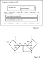
- An example of a set-up of a first image sensor 410, a second image sensor 420, a third image sensor 430, and a fourth image sensor 440 is shown in Figure 4 .
- the second and third image sensors 420, 430 are arranged in the middle without any mutual tilting whereas the first and fourth image sensors 410, 440 are arranged tilted at an angle u in relation to the second and third image sensors 420, 430, respectively.
- a first border between pixel data after processing relating to stitching and any further processing that should be processed by different processing circuits will be tilted at an angle in relation to the array of pixels. This tilting is partially due to the angle u between the first image sensor 410 and the second image sensor 420, and partially due to transformation before the processing of the system 100. Tilting of the first border may also occur for other reasons than mutual tilting between the images sensors, e.g. due to horizontal correction transformation, in an array of pixel relating to processed image data from the second and third image sensors 420, 430.
- the system 100 may for example also be used in relation to encoding of a large image frame, e.g. captured using a wide angle lens, wherein the large image frame has been divided in to two or more vertical portions.
- An array of pixels to be encoded in system 100 would then relate to pixels from two portions of the image frame.
- the pixels of the array of pixels would then typically have been processed before the array of pixel is obtained in the system 100.
- Such processing may for example include transformation of the pixel data in relation to sphere- or cylinder-projections.
- pixel data this will typically require transfer of pixel data between the two image processing circuitries.
- a first border between the pixel data of the array of pixels, processed in a different one of the two image processing circuits may be tilted in relation to the array of pixels such that the first border is curved, e.g. due to transformation of the pixel data in relation to sphere- or cylinder-projections.
- An example of a division of an image frame 500 into a first image portion 510, a second image portion 520, a third image portion 530, and a fourth image portion 540 is shown in Figure 5 .
- a first border between the pixel data of the array of pixel processed in different ones of the two image processing circuits may be tilted in relation to the array of pixels such that the first border is curved.
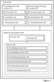
- the system 100 comprises a first image processing circuitry 110, a second image processing circuitry 120, a first encoder 112 arranged in the first image processing circuitry 110, a second encoder 122 arranged in the second image processing circuitry 120, a first buffer 114 arranged in the first image processing circuitry 110, and a second 124 buffer arranged in the second image processing circuitry 120.
- the first buffer 114 stores pixel data relating to the first subset of pixels
- the second buffer 124 stores pixel data relating to the second subset of pixels.
- the first and second processing circuitries 110, 120 may each include a first and second processor 116, 126, respectively, such as a central processing unit (CPU), microcontroller, or microprocessor.
- the first and second encoders 112, 122 may for example be adapted to encode according to H.262, H.265, H.266, AV1 and VP9 video compression standards.
- the system 100 further comprises a circuitry 130.
- the circuitry 130 is configured to carry out functions of the system 100.
- the circuitry may for example be comprised in an image processing device 300 which will be described further in relation to Figure 3 .
- the circuitry 130 may include a processor 132, such as a central processing unit (CPU), microcontroller, or microprocessor.
- the processor 132 is configured to execute program code.
- the program code may for example be configured to carry out functions of the system 100.
- the system 100 may further comprise a memory 140.
- the memory 140 may be one or more of a buffer, a flash memory, a hard drive, a removable media, a volatile memory, a non-volatile memory, a random access memory (RAM), or another suitable device.
- the memory 140 includes a non-volatile memory for long term data storage and a volatile memory that functions as system memory for the circuitry 130.
- the memory 140 may exchange data with the circuitry 130 over a data bus. Accompanying control lines and an address bus between the memory 140 and the circuitry 130 may also be present. Data may further be exchanged between the first processing circuitry 110 and the second processing circuitry 120 over a data bus.
- Functions of the system 100 may be embodied in the form of executable logic routines (e.g., lines of code, software programs, etc.) that are stored on a non-transitory computer readable medium (e.g., the memory 140) of the system 100 and are executed by the circuitry 130 (e.g., using the processor 132).
- the functions of the image processing device 100 may be a stand-alone software application or form a part of a software application that carries out additional tasks related to the image processing device 100.
- the described functions may be considered a method that a processing unit, e.g. the processor 132, of the circuitry 130 is configured to carry out.
- the described functions may be implemented in software, such functionality may as well be carried out via dedicated hardware or firmware, or some combination of hardware, firmware and/or software.
- the system 100 is intended to be used in a scenario wherein the first subset of pixels and the second subset of pixels are encoded separately in the first processing circuitry 110 and the second processing circuitry 120, respectively, it is desirable that as small amount of pixel data as possible are shared between the first and second processing circuitries 110, 120 since such sharing requires synchronization including transfer of pixel data between the first and second processing circuitries 110, 120 which will slow down the processing.
- such encoding should preferably require transfer of as small amount of pixel data as possible.
- the division into slices and tiles should be such that each tile relates to pixel data only, or mainly, from one of the first subset of pixels and the second subset of pixels, i.e. some tiles may relate to pixel data mainly from the first subset of pixels and some tiles may relate to pixel data mainly from the seconds subset of pixels.
- the circuitry 130 is configured to execute dividing functions to divide the array of pixels into slices and tiles based on the tilt angle.
- the circuitry 130 is configured to execute a first dividing function 151 configured to divide the array of pixels into two or more slices.
- the first dividing function 151 is configured to divide the array of pixels into at least 2 slices but typically not more than 100 slices and preferably into 4-16 slices.
- the circuitry 130 is further configured to execute a second dividing function 152 configured to divide each slice into two or more tiles, wherein the two or more tiles of each slice consists of a first subset of tiles and a second subset of tiles, wherein the first subset of tiles and the second subset of tiles are disjunct and the first subset of tiles is to be encoded by the first encoder 112 and the second subset of tiles is to be encoded by the second encoder 122.
- a second dividing function 152 configured to divide each slice into two or more tiles, wherein the two or more tiles of each slice consists of a first subset of tiles and a second subset of tiles, wherein the first subset of tiles and the second subset of tiles are disjunct and the first subset of tiles is to be encoded by the first encoder 112 and the second subset of tiles is to be encoded by the second encoder 122.
- the first and second subsets of tiles will each be continuous and mainly relate to pixels on one side of the first border between the first and second subsets of pixels, such that one of the first and second subsets of tiles relates to pixels on one side and the other on pixels on the other side of the first border between the first and second subsets of pixels.
- the second dividing function is further configured to set a second border between the first subset of tiles and the second subset of tiles at an offset between two adjacent slices of the two or more slices, wherein the offset is based on the tilt angle.
- the offset is selected such that the number of pixels to be encoded into the first subset of tiles of each slice that have pixel data stored in the second buffer plus the number of pixels to be encoded into the second subset of tiles of each slice that have pixel data stored in the first buffer is reduced in relation to not using an offset when the first border between the first subset of pixels and the second subset of pixels is tilted at the tilt angle v in relation to the array of pixels.
- the amount of pixel data stored in the second buffer that needs be transferred to the first encoder and the amount of pixel data stored in the first buffer that needs be transferred to the second encoder is reduced in relation to not using an offset.
- the offset may be set based on tilt angle by means of an iterative procedure such that the sum of the number of pixels to be encoded into the first subset of tiles of each slice that have pixel data stored in the second buffer and the number of pixels to be encoded into the second subset of tiles of each slice that have pixel data stored in the first buffer is determined for different offsets and the offset is set to the offset resulting in the lowest sum.
- an analytical solution may also be used where a function of the tilt angle is derived from which the offset can be calculated for a determined tilt angle.
- the second dividing function 152 is configured to divide the array of pixels into at least 2 tiles per slice.
- the number of tiles per slice may be application specific and could for example be 10 tiles per slice.
- the number of tiles per slice may be different in different slices.
- the circuitry 130 is further configured to execute a first transferring function 153 configured to transfer pixel data of pixels to be encoded into the first subset of tiles of each slice having pixel data stored in the second buffer to the first encoder, and to execute a second transferring function 154 configured to transfer pixel data of pixels to be encoded into the second subset of tiles of each slice having pixel data stored in the first buffer to the second encoder. Transferring of pixel data from the second buffer to the first encoder and from the first buffer to the second encoder may be performed via a Peripheral Component Interconnect (PCI) which results in a slower access to that image data than when the first encoder accesses image data directly in the first buffer and the second encoder accesses image data directly in the second image buffer, respectively.
- PCI Peripheral Component Interconnect
- the circuitry 130 may further be configured to execute a first instructing function 155 configured to instruct the first encoder to encode the first subset of tiles, and to execute a second instructing function 156 configured to instruct the second encoder to encode the second subset of tiles.
- the first encoder 112 is configured to encode the first subset of tiles
- the second encoder 114 is configured to encode the second subset of tiles.
- the tilt angle may be constant along the first border between the first subset of pixels and the second subset of pixels.
- the offset may then be set to be the same between each two adjacent slices.
- the tilt angle may vary along the first border between the first subset of pixels and the second subset of pixels of the array of pixels.
- the first dividing function 151 may then be configured to divide the array of pixels into three or more slices and the second dividing function may be configured to use different offsets between different two adjacent slices. Specifically, the offset used between two adjacent slices may be based a local tilt angle in the two adjacent slices.
- the local tilt angle in the two adjacent slices may be determined as an average tilt angle in the two adjacent slices.
- the first dividing function 151 may be configured to divide each separate horizontal portion of the array of pixels into two or more slices such that the array of pixels is divided into four or more slices.
- the local tilt angle for two adjacent slices in the same horizontal portion of the array of pixels may then be determined as the constant tilt angle in that horizontal portion.
- the local tilt angle for two adjacent slices in different ones of the horizontal portion of the array of pixels may be determined as the average of the two different but constant tilt angles in the two horizontal portion.
- Sizes of corresponding tiles of the two or more tiles of each of the two or more slices may either be the same or be different in each of the two or more slices. In other words, borders between tiles in the two or more slices may be horizontally aligned or not. This will depend on whether or not different sizes for corresponding tiles of different slices can be decoded or not on a decoder side for the relevant implementation. Furthermore, having the same size of corresponding tiles of the two or more slices may simplify scheduling of encoding since encoding the same size tiles will take a similar amount of time. Having the same size of corresponding tiles of the two or more slices may, when encoding a tile in one slice of the two or more slices, further enable use of image data in the respective buffer for corresponding tiles in other slices of the two or more slices.
- a method 200 for dividing an array of pixels into slices and tiles for encoding into an encoded video stream according to the present invention will be discussed with reference to Figure 2 .
- the method 200 is intended to be used in a scenario wherein the array of pixels consists of a first subset of pixels and a second subset of pixels and a first border between the first subset of pixels and the second subset of pixels is tilted at a tilt angle in relation to the array of pixels, and wherein the first subset of pixels and the second subset of pixels are processed separately in respective processing circuitries, for example in order to enable parallel processing.
- the method 200 may for example be performed in relation to encoding of a large image frame, such as a panoramic image frame constructed by stitching together image frames captured by multiple image sensors or a large image frame, e.g. captured using a wide angle lens, wherein the large image frame has been divided in to two or more portions, as described in relation to the system 100 with reference to Figure 1 , Figure 4 and Figure 5 .
- a large image frame such as a panoramic image frame constructed by stitching together image frames captured by multiple image sensors or a large image frame, e.g. captured using a wide angle lens
- the method 200 is intended to be performed in a scenario wherein the first subset of pixels and the second subset of pixels portion are encoded separately in the first processing circuitry 110 and the second processing circuitry 120, respectively, it is desirable that as little pixel data as possible is shared between the first and second processing circuitries 110, 120 since such sharing requires synchronization including transfer of pixel data between the first and second processing circuitries 110, 120 which will slow down the processing.
- transferring of pixel data from the second buffer to the first encoder and from the first buffer to the second encoder may be performed via a PCI which results in a slower access to that image data than when the first encoder accesses image data directly in the first buffer and the second encoder accesses image data directly in the second image buffer, respectively.
- each tile relates to pixel data only, or mainly, from one of the first subset of pixels or the second subset of pixels, i.e. some tiles may relate to pixel data mainly from the first subset of pixels and some tiles may relate to pixel data mainly from the second subset of pixels.
- the array of pixels is divided into slices and tiles based on the tilt angle.
- the method 200 comprises dividing S210 the array of pixels into two or more slices, and dividing S220 each slice into two or more tiles, wherein the two or more tiles of each slice consists of a first subset of tiles and a second subset of tiles, wherein the first subset of tiles and the second subset of tiles are disjunct and the first subset of tiles is to be encoded by the first encoder and the second subset of tiles is to be encoded by the second encoder.
- the first and second subsets of tiles will each be continuous and mainly relate to pixels on one side of the first border between the first and second subsets of pixels, such that one of the first and second subsets of tiles relates to pixels on one side and the other on pixels on the other side of the first border between the first and second subsets of pixels.
- Dividing S210 each slice into two or more tiles comprises setting a second border between the first subset of tiles and the second subset of tiles at an offset between two adjacent slices of the two or more slices, wherein the offset is based on the tilt angle.
- the offset is selected such that the number of pixels to be encoded into the first subset of tiles of each slice that have pixel data stored in the second buffer plus the number of pixels to be encoded into the second subset of tiles of each slice that have pixel data stored in the first buffer is reduced in relation to not using an offset when the first border between the first subset of pixels and the second subset of pixels is tilted at the tilt angle v in relation to the array of pixels.
- the amount of pixel data stored in the second buffer that needs be transferred to the first encoder and the amount of pixel data stored in the first buffer that needs be transferred to the second encoder is reduced in relation to not using an offset.
- the offset may be set based on tilt angle by means of an iterative procedure such that the sum of the number of pixels to be encoded into the first subset of tiles of each slice that have pixel data stored in the second buffer and the number of pixels to be encoded into the second subset of tiles of each slice that have pixel data stored in the first buffer is determined for different offsets and the offset is set to the offset resulting in the lowest sum.
- the method 200 and its included steps may be further adapted as the corresponding functions system 100 as described in relation to Figure 1 .
- the slices and tiles are intended to be encoded into an encoded video stream by means of a first encoder arranged in a first image processing circuitry and a second encoder arranged in a second image processing circuitry.
- the image processing device 300 is intended to be used in a scenario wherein the array of pixels consists of a first subset of pixels and a second subset of pixels and a border first between the first subset of pixels and the second subset of pixels is tilted at a tilt angle in relation to the array of pixels, and wherein the first subset of pixels and the second subset of pixels are processed separately, for example in order to enable parallel processing.
- the image processing device 300 may for example be used in relation to encoding of a large image frame, such as a panoramic image frame constructed by stitching together image frames captured by multiple image sensors or a large image frame, e.g. captured using a wide angle lens, wherein the large image frame has been divided in to two or more portions, as described in relation to the system 100 with reference to Figure 1 , Figure 4 and Figure 5 .
- the image processing device 300 may be included in a system, such as the system 100 described with reference to Figure 1 .
- the image processing device 300 comprises a circuitry 130.
- the circuitry 130 is configured to carry out functions of the system 100.
- the circuitry 130 may include a processor 132, such as a central processing unit (CPU), microcontroller, or microprocessor.
- the processor 132 is configured to execute program code.
- the program code may for example be configured to carry out functions of the system 100.
- the image processing device 300 may further comprise a memory 140.
- the memory 340 may be one or more of a buffer, a flash memory, a hard drive, a removable media, a volatile memory, a non-volatile memory, a random access memory (RAM), or another suitable device.
- the memory 140 includes a non-volatile memory for long term data storage and a volatile memory that functions as system memory for the circuitry 130.
- the memory 140 may exchange data with the circuitry 130 over a data bus. Accompanying control lines and an address bus between the memory 140 and the circuitry 130 may also be present. Data may further be exchanged between the first processing circuitry 110 and the second processing circuitry 120 over a data bus.
- Functions of the image processing device 300 may be embodied in the form of executable logic routines (e.g., lines of code, software programs, etc.) that are stored on a non-transitory computer readable medium (e.g., the memory 140) of the image processing device 300 and are executed by the circuitry 130 (e.g., using the processor 132).
- the functions of the image processing device 300 may be a stand-alone software application or form a part of a software application that carries out additional tasks related to the image processing device 300.
- the described functions may be considered a method that a processing unit, e.g. the processor 132, of the circuitry 130 is configured to carry out.
- the described functions may be implemented in software, such functionality may as well be carried out via dedicated hardware or firmware, or some combination of hardware, firmware and/or software.
- the image processing device 300 is intended to be used in a scenario wherein the first subset of pixels and the second subset of pixels are processed separately in a first processing circuitry 110 and a second processing circuitry 120, respectively, it is desirable that as little pixel data as possible are shared between the first and second processing circuitries 110, 120 since such sharing requires synchronization including transfer of pixel data between the first and second processing circuitries 110, 120 which will slow down the processing.
- such encoding should preferably require transfer of as little pixel data as possible.
- the division into slices and tiles should be such that each tile relates to pixel data mainly from one of the first subset of pixels and the second subset of pixels, i.e. some tiles may relate to pixel data mainly from the first subset of pixels and some tiles may relate to pixel data mainly from the seconds subset of pixels.
- the circuitry 130 is configured to execute dividing functions to divide the array of pixels into slices and tiles based on the tilt angle.
- the circuitry 130 is configured to execute a first dividing function 151 configured to divide the array of pixels into two or more slices.
- the circuitry 130 is further configured to execute a second dividing function 152 configured to divide each slice into two or more tiles, wherein the two or more tiles of each slice consists of a first subset of tiles and a second subset of tiles, wherein the first subset of tiles and the second subset of tiles are disjunct and the first subset of tiles is to be encoded by the first encoder and the second subset of tiles is to be encoded by the second encoder.
- a second dividing function 152 configured to divide each slice into two or more tiles, wherein the two or more tiles of each slice consists of a first subset of tiles and a second subset of tiles, wherein the first subset of tiles and the second subset of tiles are disjunct and the first subset of tiles is to be encoded by the first encoder and the second subset of tiles is to be encoded by the second encoder.
- the first and second subsets of tiles will each be continuous and mainly relate to pixels on one side of the first border between the first and second subsets of pixels, such that one of the first and second subsets of tiles relates to pixels on one side and the other on pixels on the other side of the first border between the first and second subsets of pixels.
- the second dividing function is further configured to set a second border between the first subset of tiles and the second subset of tiles at an offset between two adjacent slices of the two or more slices, wherein the offset is based on the tilt angle.
- the offset is selected such that the number of pixels to be encoded into the first subset of tiles of each slice that have pixel data stored in the second buffer plus the number of pixels to be encoded into the second subset of tiles of each slice that have pixel data stored in the first buffer is reduced in relation to not using an offset when the first border between the first subset of pixels and the second subset of pixels is tilted at the tilt angle v in relation to the array of pixels.
- the amount of pixel data stored in the second buffer that needs be transferred to the first encoder and the amount of pixel data stored in the first buffer that needs be transferred to the second encoder is reduced in relation to not using an offset.
- the offset may be set based on tilt angle by means of an iterative procedure such that the sum of the number of pixels to be encoded into the first subset of tiles of each slice that have pixel data stored in the second buffer and the number of pixels to be encoded into the second subset of tiles of each slice that have pixel data stored in the first buffer is determined for different offsets and the offset is set to the offset resulting in the lowest sum.
- the image processing device 300 and its included functions may be further adapted as the corresponding functions of the system 100 as described in relation to Figure 1 .
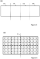
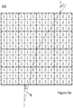
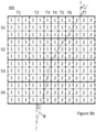
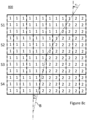
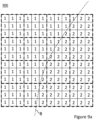
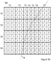
- Figures 7a-b , Figures 8a-d , Figures 9a-d and Figures 10a-d each square in thin solid lines and including a figure "1 " or " 2 " either corresponds to a single pixel or to a pixel block comprising more than one pixel, each square or rectangle in bold dashed lines corresponds to a tile, and each horizontal bold line indicates a fourth border between slices.
- the array of pixels 700 is divided into eight square tiles each consisting of nine pixels or pixel blocks, but the array of pixels 700 is not divided into any slices.
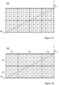
- figure 7b the array of pixels 700 is divided into two slices each being three pixels or pixel blocks in height, and each slice is divided into three tiles. Four of the tiles consists of nine pixels or pixel blocks and two of the tiles consists of eighteen pixels or pixel blocks.
- FIG. 6 a first example of division of an array of pixels 600 into tiles where a first border B between a first subset of pixels and a second subset of pixels is horizontal, i.e. parallel with a column in the array of pixels.
- the first subset of pixels consists of the squares indicated with the figure "1 " and the second subset of pixels consists of the squares indicated with the figure "2 ".
- Each square could correspond to a single pixel or a block of pixels comprising more than one pixel.
- FIG. 7a-b for a second example in which an array of pixels 700 is divided into tiles or into slices and tiles where a first border B between a first subset of pixels and a second subset of pixels is tilted at a constant tilt angle v.
- the first subset of pixels consists of the squares indicated with the figure "1 " and the second subset of pixels consists of the squares indicated with the figure "2 ".
- the first subset of pixels has pixel data buffered in the first buffer in the first processing circuitry and the second subset of pixels has pixel data buffered in the first buffer in the first processing circuitry.
- Each square could correspond to a single pixel or a block of pixels comprising more than one pixel.
- the array of pixels 700 has been divided into eight tiles - four columns of tiles with two tiles in each column - according to a prior art method.
- the pixels of the four tiles in the first two columns from the left are encoded by the first encoder in the first processing circuitry and four tiles in the last two columns from the left are encoded by the second encoder in the second processing circuitry.
- the array of pixels 700 is first divided into two or more slices and each slice is then be divided into two or more tiles, wherein the two or more tiles of each slice consists of a first subset of tiles and a second subset of tiles, wherein the first subset of tiles and the second subset of tiles are disjunct and the first subset of tiles is to be encoded by the first encoder and the second subset of tiles is to be encoded by the second encoder.
- a second border between the first subset of tiles and the second subset of tiles is set at an offset between two adjacent slices of the two or more slices, wherein the offset is based on the tilt angle.
- the division into slices and tiles of the method used in relation to Figure 7b further requires that corresponding tiles in each slice (tiles in a same column of tiles) have to be of the same size, i.e. of the same width.
- the array of pixels 700 has been divided into a first slice S1 and a second slice S2.
- the first slice S1 has been divided into three tiles T1, T2, T3 wherein the first and second tiles T1, T2 belong to a first subset of tiles and the third tile T3 belongs to a second subset of tiles.
- the first and second subsets of tiles of the first slice S1 are disjunct, i.e. each tile only belongs to one of the first and second subsets of tiles.
- the second slice S2 has been divided into three tiles T1, T2, T3 wherein the first tile T1 belongs to a first subset of tiles and the second and third tiles T2, T3 belong to a second subset of tiles.
- the first and second subsets of tiles of the second slice S2 are disjunct, i.e. each tile only belongs to one of the first and second subsets of tiles.
- the second border between the first and second subsets of tiles of the first slice S1 and the second border between the first and second subsets of tiles of the second slice S2 are offset in relation to each other based on the tilt angle v of the first border B.
- the offset is selected such that the number of pixels to be encoded into the first subset of tiles of each slice that have pixel data stored in the second buffer plus the number of pixels to be encoded into the second subset of tiles of each slice that have pixel data stored in the first buffer is reduced in relation to not using an offset when the first border B between the first subset of pixels and the second subset of pixels is tilted at the tilt angle v in relation to the array of pixels.
- the amount of pixel data stored in the second buffer that needs be transferred to the first encoder and the amount of pixel data stored in the first buffer that needs be transferred to the second encoder is reduced in relation to not using an offset.
- the offset may be set based on tilt angle by means of an iterative procedure such that the sum of the number of pixels to be encoded into the first subset of tiles of each slice that have pixel data stored in the second buffer and the number of pixels to be encoded into the second subset of tiles of each slice that have pixel data stored in the first buffer is determined for different offsets and the offset is set to the offset resulting in the lowest sum.
- pixel data of pixels corresponding to two squares have to be transferred from the second processing circuitry to the first circuitry when encoding the first subset of tiles, i.e. the first and second tiles T1,T2, of the first slice S1
- pixel data of pixels corresponding to two squares has to be transferred from the first processing circuitry to the second circuitry when encoding the second subset of tiles, i.e. the third tile T3, of the first slice S1.
- pixel data of pixels corresponding to two squares have to be transferred from the second processing circuitry to the first circuitry when encoding the first subset of tiles, i.e.
- the first tile T1, of the second slice S2, and pixel data of pixels corresponding to two squares have to be transferred from the first processing circuitry to the second circuitry when encoding the second subset of tiles, i.e. the second and third tiles T2, T3, of the second slice S2.
- the second subset of tiles i.e. the second and third tiles T2, T3, of the second slice S2.
- the offset in Figure 7b is six squares. If the tilt angle would have been smaller, the offset would have been smaller and vice versa.
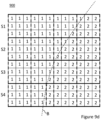
- Figures 8a-d for a third example in which an array of pixels 800 is divided into tiles or into slices and tiles where a first border B between a first subset of pixels and a second subset of pixels is tilted at a tilt angle v 1 v 2 that varies along the first border B, such that in a first horizontal portion of the array of pixels 800 the first border B has a first tilt angle v 1 that is constant and in a second horizontal portion of the array of pixels 800 the first border B has a second tilt angle v 2 that is constant but different from the first tilt angle v 1 .
- the first subset of pixels consists of the squares indicated with the figure "1 " and the second subset of pixels consists of the squares indicated with the figure "2 ".
- the first subset of pixels has pixel data buffered in the first buffer in the first processing circuitry and the second subset of pixels has pixel data buffered in the first buffer in the first processing circuitry.
- Each square could correspond to a single pixel or a block of pixels comprising more than one pixel.
- the array of pixels 800 has been divided into sixteen tiles - four columns of tiles with four tiles in each column - according to a prior art method.
- the pixels of the eight tiles in the first two columns from the left are encoded by the first encoder in the first processing circuitry and eight tiles in the last two columns from the left are encoded by the second encoder in the second processing circuitry.
- the array of pixels 800 is first divided into two or more slices and each slice is then divided into two or more tiles, wherein the two or more tiles of each slice consists of a first subset of tiles and a second subset of tiles, wherein the first subset of tiles and the second subset of tiles are disjunct and the first subset of tiles is to be encoded by the first encoder and the second subset of tiles is to be encoded by the second encoder.
- a second border between the first subset of tiles and the second subset of tiles is set at an offset between two adjacent slices of the two or more slices, wherein the offset is based on the tilt angle v 1 v 2 .
- the division into slices and tiles of the method used in relation to Figure 8b further requires that corresponding tiles in each slice (tiles in a same column of tiles) have to be of the same size, i.e. of the same width.
- the tilt angle v 1 v 2 is constant but different in two horizontal portions and the two horizontal portions are divided into two slices each.
- the array of pixels 800 has been divided into a first slice S1, a second slice S2, a third slice S3, and a fourth slice S4.
- the first slice S1 has been divided into seven tiles T1-T7, wherein the first to sixth tiles T1-T6 belong to a first subset of tiles of the first slice S1 and the seventh tile T7 belongs to a second subset of tiles of the first slice S1.
- the second slice S2 has been divided into seven tiles T1-T7, wherein the first to fourth tiles T1-T4 belong to a first subset of tiles of the second slice S2 and the fifth to seventh tiles T5-T7 belong to a second subset of tiles of the second slice S2.
- the third slice S3 has been divided into seven tiles T1-T7, wherein the first to third tiles T1-T3 belong to a first subset of tiles of the third slice S3 and the fourth to seventh tiles T4-T7 belong to a second subset of tiles of the third slice S3.
- the fourth slice S4 has been divided into seven tiles T1-T7, wherein the first and second tiles T1, T2 belong to a first subset of tiles of the fourth slice S4 and the third to seventh tiles T3-T7 belong to a second subset of tiles of the fourth slice S4.
- the first and second subsets of tiles of each of the slices are disjunct, i.e. each tile only belongs to one of the first and second subsets of tiles.
- the second border between the first and second subsets of tiles of the first slice S1 and the second border between the first and second subsets of tiles of the second slice S2 are offset in relation to each other based on the local tilt angle v 1 of the first border B in the horizontal portion the third and fourth slices S3, S4.
- the second border between the first and second subsets of tiles of the second slice S2 and the second border between the first and second subsets of tiles of the third slice S2 are offset in relation to each other based on the local tilt angle v 1 v 2 of the first border B in the horizontal portion the second and third slices S2, S3.
- the local tilt angle in the second and third slices S2, S3 can be determined as the average of the first and second tilt angles v 1 v 2 .
- the second border between the first and second subsets of tiles of the third slice S3 and the second border between the first and second subsets of tiles of the fourth slice S4 are offset in relation to each other based on the local tilt angle v 2 of the first border B in the horizontal portion the third and fourth slices S3, S4 are located.
- the respective offset between each two adjacent slices is selected such that the number of pixels to be encoded into the first subset of tiles of each slice that have pixel data stored in the second buffer plus the number of pixels to be encoded into the second subset of tiles of each slice that have pixel data stored in the first buffer is reduced in relation to not using an offset when the first border B between the first subset of pixels and the second subset of pixels is tilted at the varying tilt angle v 1 v 2 in relation to the array of pixels.
- the amount of pixel data stored in the second buffer that needs be transferred to the first encoder and the amount of pixel data stored in the first buffer that needs be transferred to the second encoder is reduced in relation to not using an offset.
- pixel data of pixels corresponding to one square have to be transferred from the second processing circuitry to the first circuitry when encoding the first subset of tiles, i.e. the first to sixth tiles T1-T6, of the first slice S1
- pixel data of pixels corresponding to one square have to be transferred from the first processing circuitry to the second circuitry when encoding the second subset of tiles, i.e. the seventh tile T7, of the first slice S1.
- pixel data of pixels corresponding to one square has to be transferred from the second processing circuitry to the first circuitry when encoding the first subset of tiles, i.e.
- pixel data of pixels corresponding to one square has to be transferred from the first processing circuitry to the second circuitry when encoding the second subset of tiles, i.e. the fifth to seventh tiles T5-T7, of the second slice S2. Furthermore, pixel data of pixels corresponding to one square have to be transferred from the second processing circuitry to the first circuitry when encoding the first subset of tiles, i.e. the first to third tiles T1-T3, of the third slice S3, and pixel data of pixels corresponding to zero squares have to be transferred from the first processing circuitry to the second circuitry when encoding the second subset of tiles, i.e.
- the offset in Figure 8b is two squares between the first and second slice, one square between the second and third slices S2, S3, and one square between the third and fourth slices S3, S4. If the tilt angle would have been smaller in any of the adjacent slices, the offset would have been smaller between those adjacent slices and vice versa.
- FIG 8c wherein a division of the array of pixels 800 into slices and tiles according to the present invention is illustrated for the third example.
- the array of pixels 800 has been divided into first to fourth slices S1, S2, S3, S4.
- the first slice S1 has been divided into four tiles, wherein the first three tiles from the left belong to a first subset of tiles of the first slice S1 and the last tile belongs to a second subset of tiles of the first slice S1.
- the second slice S2 has been divided into five tiles, wherein the first three tiles belong to a first subset of tiles of the second slice S2 and the last two tiles belong to a second subset of tiles of the second slice S2.
- the third slice S3 has been divided into four tiles, wherein the first two tiles from the left belong to a first subset of tiles of the third slice S3 and the last two tiles belong to a second subset of tiles of the third slice S3.
- the fourth slice S4 has been divided into five tiles, wherein the first two tiles from the left belong to a first subset of tiles of the fourth slice S4 and the last three tiles belong to a second subset of tiles of the fourth slice S4.
- the first and second subsets of tiles of each of the slices are disjunct, i.e. each tile only belongs to one of the first and second subsets of tiles.
- the second border between the first and second subsets of tiles of the first slice S1 and the second border between the first and second subsets of tiles of the second slice S2 are offset in relation to each other based on the local tilt angle v 1 of the first border B in the horizontal portion the first and second slices S1, S2.
- the second border between the first and second subsets of tiles of the second slice S2 and the second border between the first and second subsets of tiles of the third slice S3 are offset in relation to each other based on the local tilt angles v 1 and v 2 of the first border B in the horizontal portion the second and third slices S2, S3.
- the local tilt angle in the second and third slices S2, S3 can be determined as the average of the first and second tilt angles v 1 v 2 .
- the second border between the first and second subsets of tiles of the third slice S3 and the second border between the first and second subsets of tiles of the fourth slice S4 are offset in relation to each other based on the local tilt angle v 2 of the first border B in the horizontal portion the third and fourth slices S3, S4.
- the respective offset between each two adjacent slices is selected such that the number of pixels to be encoded into the first subset of tiles of each slice that have pixel data stored in the second buffer plus the number of pixels to be encoded into the second subset of tiles of each slice that have pixel data stored in the first buffer is reduced in relation to not using an offset when the first border B between the first subset of pixels and the second subset of pixels is tilted at a tilt angle v 1 or v 2 , or at a varying tilt angle v 1 v 2 , in relation to the array of pixels.
- the amount of pixel data stored in the second buffer that needs be transferred to the first encoder and the amount of pixel data stored in the first buffer that needs be transferred to the second encoder is reduced in relation to not using an offset.
- pixel data of pixels corresponding to one square have to be transferred from the second processing circuitry to the first circuitry when encoding the first subset of tiles, i.e. the first to third tiles, of the first slice S1
- pixel data of pixels corresponding to one square have to be transferred from the first processing circuitry to the second circuitry when encoding the second subset of tiles, i.e. the fourth tile, of the first slice S1.
- pixel data of pixels corresponding to one square have to be transferred from the second processing circuitry to the first circuitry when encoding the first subset of tiles, i.e.
- pixel data of pixels corresponding to one square have to be transferred from the first processing circuitry to the second circuitry when encoding the second subset of tiles, i.e. the fourth and fifth tiles, of the second slice S2. Furthermore, pixel data of pixels corresponding to one square have to be transferred from the second processing circuitry to the first circuitry when encoding the first subset of tiles, i.e. the first and second tiles , of the third slice S3, and pixel data of pixels corresponding to zero squares have to be transferred from the first processing circuitry to the second circuitry when encoding the second subset of tiles, i.e. the third and fourth tiles, of the third slice S3.
- pixel data of pixels corresponding to zero squares have to be transferred from the second processing circuitry to the first circuitry when encoding the first subset of tiles, i.e. the first and second tiles, of the fourth slice S4, and pixel data of pixels corresponding to zero squares have to be transferred from the first processing circuitry to the second circuitry when encoding the second subset of tiles, i.e. the third to fifth tiles, of the fourth slice S4.
- pixel data of pixels corresponding to five squares have to be transferred between the two processing circuitries using the method 200 of the present invention in this example.
- the offset in Figure 8c is two squares between the first and second slice S1, S2, one square between the second and third slices S2, S3, and one square between the third and fourth slices S3, S4. If the tilt angle would have been smaller in any of the adjacent slices, the offset would have been smaller between those adjacent slices and vice versa.
- each slice has been divided into more than two tiles.
- each slice could have also been divided into two tiles , one on each side of the first border.
- dividing the slices into more than two tiles where the tiles are of similar sizes may simplify scheduling of encoding since encoding the similar size tiles will take a similar amount of time.
- this enable use of image data in the respective buffer for corresponding tiles in other slices of the two or more slices.
- Figure 8d shows a division into slices and tiles of the array of pixels 800 for a case where it is required that corresponding tiles in each slice (tiles in a same column of tiles) except for tiles at the first border B between the first subset of pixels and the second subset of pixels have to be of the same size, i.e. of the same width. As can be seen, most corresponding tiles in the slices are of the same size.
- the width of tiles at the first border B between the first subset of pixels and the second subset of pixels in the second slice S2 and in the fourth slice S4 have been adapted and arranged such that the second border between the first subset of tiles and the second subset of tiles is arranged at an offset in relation to their respective adjacent slices in order to reduce the total amount of pixel data of pixels that has to be transferred between the two processing circuitries as comparted to prior art.
- the offset of the second border between the first and second slices S1, S2 is two squares and, the offset of the second border between the second and third slices S2, S3 is one square, and the offset of the second border between the third and fourth slices S3, S4 is one square.
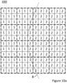
- FIG. 9a-d for a fourth example in which an array of pixels 900 is divided into tiles or into slices and tiles where a first border B between a first subset of pixels and a second subset of pixels is tilted at a tilt angle that varies along the first border B, such that the first border B is curved.
- the first subset of pixels consists of the squares indicated with the figure "1 " and the second subset of pixels consists of the squares indicated with the figure "2 ".
- the first subset of pixels has pixel data buffered in the first buffer in the first processing circuitry and the second subset of pixels has pixel data buffered in the first buffer in the first processing circuitry.
- Each square could correspond to a single pixel or a block of pixels comprising more than one pixel.
- the first border B between the first subset of pixels and the second subset of pixels of the array of pixels 900 in Figures 9a-d is also tilted at a varying tilt angle but not at a constant tilt angle in two horizontal portions of the array of pixels 900 it is instead it curved.
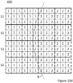
- Figures 10a-d for a fifth example in which an array of pixels 1000 is divided into tiles or into slices and tiles where a first border B between a first subset of pixels and a second subset of pixels is tilted at a tilt angle that varies along the first border B, such that the first border B is curved.
- the first subset of pixels consists of the squares indicated with the figure "1 " and the second subset of pixels consists of the squares indicated with the figure "2 ".
- the first subset of pixels has pixel data buffered in the first buffer in the first processing circuitry and the second subset of pixels has pixel data buffered in the first buffer in the first processing circuitry.
- Each square could correspond to a single pixel or a block of pixels comprising more than one pixel.
- the array of pixels 1000 has been divided into sixteen tiles - four columns of tiles with four tiles in each column - according to a prior art method.
- the pixels of the eight tiles in the first two columns from the left are encoded by the first encoder in the first processing circuitry and eight tiles in the last two columns from the left are encoded by the second encoder in the second processing circuitry.
- the array of pixels 1000 is first divided into two or more slices and each slice is then divided into two or more tiles, wherein the two or more tiles of each slice consists of a first subset of tiles and a second subset of tiles, wherein the first subset of tiles and the second subset of tiles are disjunct and the first subset of tiles is to be encoded by the first encoder and the second subset of tiles is to be encoded by the second encoder.
- a second border between the first subset of tiles and the second subset of tiles is set at an offset between two adjacent slices of the two or more slices, wherein the offset is based on the tilt angle.
- the division into slices and tiles of the method used in relation to Figure 10b further requires that corresponding tiles in each slice (tiles in a same column of tiles) have to be of the same size, i.e. of the same width.
- the tilt angle varies along the first border B such that the first border B is curved.
- the array of pixels 1000 has been divided into a first to fourth slices S1, S2, S3, S4.
- the first slice S1 has been divided into five tiles T1-T5, wherein the first to third tiles T1-T3 belong to a first subset of tiles of the first slice S1 and the fourth and fifth tile T4-T5 belong to a second subset of tiles of the first slice S1.
- the second slice S2 has been divided into five tiles T1-T5, wherein the first and second tiles T1, T2 belong to a first subset of tiles of the second slice S2 and the third to fifth tiles T3-T5 belong to a second subset of tiles of the second slice S2.
- the third slice S3 has been divided into five tiles T1-T5, wherein the first and second tiles T1, T2 belong to a first subset of tiles of the third slice S3 and the third to fifth tiles T3-T5 belong to a second subset of tiles of the third slice S3.
- the fourth slice S4 has been divided into five tiles T1-T5, wherein the first to third tiles T1-T3 belong to a first subset of tiles of the fourth slice S4 and the fourth and fifth tiles T4, T5 belong to a second subset of tiles of the fourth slice S4.
- the first and second subsets of tiles of each of the slices are disjunct, i.e. each tile only belongs to one of the first and second subsets of tiles.
- the second border between the first and second subsets of tiles of the first slice S1 and the second border between the first and second subsets of tiles of the second slice S2 are offset in relation to each other based on the local tilt angle of the first border B in the horizontal portion the first and second slices S1, S2.
- the second border between the first and second subsets of tiles of the second slice S2 and the second border between the first and second subsets of tiles of the third slice S3 are offset in relation to each other based on the local tilt angle of the first border B in the second and third slices S2, S3.
- the second border between the first and second subsets of tiles of the third slice S3 and the second border between the first and second subsets of tiles of the fourth slice S4 are offset in relation to each other based on the local tilt angle of the first border B in the third and fourth slices S3, S4.
- the local tilt angle in each two adjacent slices can be determined as the average of the tilt angle of the portion of the curved first border B in that pair of adjacent slices.
- the respective offset between each two adjacent slices is selected such that the number of pixels to be encoded into the first subset of tiles of each slice that have pixel data stored in the second buffer plus the number of pixels to be encoded into the second subset of tiles of each slice that have pixel data stored in the first buffer is reduced in relation to not using an offset when the first border B between the first subset of pixels and the second subset of pixels is tilted at the varying tilt angle in relation to the array of pixels.
- the amount of pixel data stored in the second buffer that needs be transferred to the first encoder and the amount of pixel data stored in the first buffer that needs be transferred to the second encoder is reduced in relation to not using an offset.
- pixel data of pixels corresponding to zero squares have to be transferred from the second processing circuitry to the first circuitry when encoding the first subset of tiles, i.e. the first to third tiles T1-T3, of the first slice S1
- pixel data of pixels corresponding to zero squares have to be transferred from the first processing circuitry to the second circuitry when encoding the second subset of tiles, i.e. the fourth and fifth tiles T4, T5, of the first slice S1.
- pixel data of pixels corresponding to zero squares have to be transferred from the second processing circuitry to the first circuitry when encoding the first subset of tiles, i.e.
- the first and second tiles T1, T2, of the second slice S2 and pixel data of pixels corresponding to zero squares have to be transferred from the first processing circuitry to the second circuitry when encoding the second subset of tiles, i.e. the third to fifth tiles T3-T5, of the second slice S2.
- pixel data of pixels corresponding to zero squares have to be transferred from the second processing circuitry to the first circuitry when encoding the first subset of tiles, i.e. the first to second tiles T1-T2, of the third slice S3, and pixel data of pixels corresponding to zero squares have to be transferred from the first processing circuitry to the second circuitry when encoding the second subset of tiles, i.e.
- the offset in Figure 10b is one square between the first and second slices S1, S2, zero squares between the second and third slices S2, S3, and one square between the third and fourth slices S3, S4. If the tilt angle would have been smaller in any of the adjacent slices, the offset would have been smaller between those adjacent slices and vice versa.
- FIG. 10c wherein a division of the array of pixels 1000 into slices and tiles according to the present invention is illustrated for the third example.
- the division into slices and tiles of the method used in relation to Figure 10c there is no restriction in relation to size of tiles in different slices. at corresponding tiles in each slice. Hence the size and position in slice of the tiles can be set independently. Consequently, as can be seen in Figure 10c , the array of pixels 1000 has been divided into first to fourth slices S1, S2, S3, S4.
- the first slice S1 has been divided into four tiles, wherein the first two tiles from the left belong to a first subset of tiles of the first slice S1 and the last two tiles belong to a second subset of tiles of the first slice S1.
- the second slice S2 has been divided into five tiles, wherein the first two tiles belong to a first subset of tiles of the second slice S2 and the last three tiles belong to a second subset of tiles of the second slice S2.
- the third slice S3 has been divided into five tiles, wherein the first two tiles from the left belong to a first subset of tiles of the third slice S3 and the last three tiles belong to a second subset of tiles of the third slice S3.
- the fourth slice S4 has been divided into four tiles, wherein the first two tiles from the left belong to a first subset of tiles of the fourth slice S4 and the last two tiles belong to a second subset of tiles of the fourth slice S4.
- the first and second subsets of tiles of each of the slices are disjunct, i.e. each tile only belongs to one of the first and second subsets of tiles.
- the second border between the first and second subsets of tiles of the first slice S1 and the second border between the first and second subsets of tiles of the second slice S2 are offset in relation to each other based on the local tilt angle of the first border B in the horizontal portion the first and second slices S1, S2.
- the second border between the first and second subsets of tiles of the second slice S2 and the border between the first and second subsets of tiles of the third slice S3 are offset in relation to each other based on the local tilt angle of the first border B in the second and third slices S2, S3.
- the second border between the first and second subsets of tiles of the third slice S3 and the border second between the first and second subsets of tiles of the fourth slice S4 are offset in relation to each other based on the local tilt angle of the first border B in the third and fourth slices S3, S4.
- the local tilt angle in each two adjacent slices can be determined as the average of the tilt angle of the portion of the curved first border B in that pair of adjacent slices.
- the respective offset between each two adjacent slices is selected such that the number of pixels to be encoded into the first subset of tiles of each slice that have pixel data stored in the second buffer plus the number of pixels to be encoded into the second subset of tiles of each slice that have pixel data stored in the first buffer is reduced in relation to not using an offset when the first border B between the first subset of pixels and the second subset of pixels is tilted at the varying tilt angle in relation to the array of pixels.
- the amount of pixel data stored in the second buffer that needs be transferred to the first encoder and the amount of pixel data stored in the first buffer that needs be transferred to the second encoder is reduced in relation to not using an offset.
- pixel data of pixels corresponding to zero squares have to be transferred from the second processing circuitry to the first circuitry when encoding the first subset of tiles, i.e. the first and second tile, of the second slice S2, and pixel data of pixels corresponding to zero squares have to be transferred from the first processing circuitry to the second circuitry when encoding the second subset of tiles, i.e. the third to fifth tiles, of the second slice S2. Furthermore, pixel data of pixels corresponding to zero squares have to be transferred from the second processing circuitry to the first circuitry when encoding the first subset of tiles, i.e.
- the offset in Figure 10c is one square between the first and second slice S1, S2, zero squares between the second and third slices S2, S3, and one square between the third and fourth slices S3, S4. If the tilt angle would have been smaller in any of the adjacent slices, the offset would have been smaller between those adjacent slices and vice versa.
- Figure 10d shows a division into slices and tiles of the array of pixels 1000 for a case where it is required that corresponding tiles in each slice (tiles in a same column of tiles) except for tiles at the first border B between the first subset of pixels and the second subset of pixels have to be of the same size, i.e. of the same width. As can be seen most corresponding tiles in the slices are of the same size.
- the width of tiles at the first border B between the first subset of pixels and the second subset of pixels in the second slice S2 and in the third slice S3 have been adapted and arranged such that the second border between the first subset of tiles and the second subset of tiles is arranged at an offset in relation to their respective adjacent slices in order to reduce the total amount of pixel data of pixels that has to be transferred between the two processing circuitries as comparted to prior art.
- the offset of the second border between the first and second slices S1, S2 is one squares and, the offset of the second border between the second and third slices S2, S3 is zero squares, and the offset of the second border between the third and fourth slices S3, S4 is one square.
- the examples have all been described in relation to slices with equal size, i.e. equal heights in number of pixels/pixel blocks.
- different size slices may be used.
- division into different size slices may be beneficial in differing horizontal portions of the array of pixels.
Landscapes
- Engineering & Computer Science (AREA)
- Multimedia (AREA)
- Signal Processing (AREA)
- Compression Or Coding Systems Of Tv Signals (AREA)
Claims (15)
- Procédé pour diviser un réseau de pixels en tranches et en pavés pour coder ce réseau de pixels en un flux vidéo codé au moyen d'un premier codeur disposé dans une première circuiterie de traitement d'images et d'un deuxième codeur disposé dans une deuxième circuiterie de traitement d'images, les pixels de ce réseau de pixels étant disposés à des intervalles réguliers le long d'une direction verticale et d'une direction horizontale, chaque tranche étant séparée, par une ligne horizontale droite sur toute la largeur du réseau, des tranches adjacentes respectives et étant codée sans avoir besoin d'accéder aux données d'image relatives à d'autres tranches et chaque pavé étant séparé, par une ligne verticale droite sur toute la hauteur d'une tranche, des pavés adjacents respectifs dans la même tranche et étant codé sans avoir besoin d'accéder à des données d'image relatives à d'autres pavés, le réseau de pixels consistant en un premier sous-ensemble de pixels ayant des données de pixels stockées dans une première mémoire tampon disposée dans la première circuiterie de traitement d'images et en un deuxième sous-ensemble de pixels ayant des données de pixels stockées dans une deuxième mémoire tampon disposée dans la deuxième circuiterie de traitement d'images, une première bordure entre le premier sous-ensemble de pixels et le deuxième sous-ensemble de pixels étant inclinée à un angle d'inclinaison par rapport au réseau de pixels, ce procédé comprenant :la division du réseau de pixels en deux tranches ou plus ; etla division de chaque tranche en deux pavés ou plus, les deux pavés ou plus de chaque tranche consistant en un premier sous-ensemble de pavés et en un deuxième sous-ensemble de pavés, le premier sous-ensemble de pavés et le deuxième sous-ensemble de pavés étant disjoints et le premier sous-ensemble de pavés devant être codé par le premier codeur et le deuxième sous-ensemble de pavés devant être codé par le deuxième codeur,l'acte de division de chaque tranche en deux pavés ou plus comprenant l'établissement d'une deuxième bordure entre le premier sous-ensemble de pavés et le deuxième sous-ensemble de pavés à un décalage le long de la direction horizontale entre deux tranches adjacentes des deux tranches ou plus de telle sorte que les deuxièmes bordures entre le premier sous-ensemble de pavés et le deuxième sous-ensemble de pavés dans deux tranches adjacentes ne sont pas alignées le long de la direction horizontale, le décalage étant basé sur l'angle d'inclinaison de telle sorte que le nombre de pixels devant être codés en le premier sous-ensemble de pavés de chaque tranche ayant des données de pixels stockées dans la deuxième mémoire tampon plus le nombre de pixels devant être codés en le deuxième sous-ensemble de pavés de chaque tranche qui ont des données de pixels stockées dans la première mémoire tampon sont réduits relativement à la non utilisation d'un décalage.
- Procédé selon la revendication 1, dans lequel l'angle d'inclinaison est constant le long de la première bordure entre le premier sous-ensemble de pixels et le deuxième sous-ensemble de pixels.
- Procédé selon la revendication 1, dans lequel l'angle d'inclinaison varie le long de la première bordure entre le premier sous-ensemble de pixels et le deuxième sous-ensemble de pixels,l'acte de division du réseau de pixels en deux tranches ou plus comprenant la division du réseau de pixels en trois tranches ou plus,l'acte de division de chaque tranche en deux pavés ou plus comprenant, pour chaque paire de tranches adjacentes des trois trois tranches ou plus, l'établissement de la deuxième bordure entre le premier sous-ensemble de pavés et le deuxième sous-ensemble de pavés de chaque tranche des deux tranches adjacentes ou plus à un décalage, ce décalage étant basé sur un angle d'inclinaison local de la première bordure entre le premier sous-ensemble de pixels et le deuxième sous-ensemble de pixels dans les deux tranches adjacentes.
- Procédé selon la revendication 3, dans lequel la première bordure entre le premier sous-ensemble de pixels et le deuxième sous-ensemble de pixels est courbe.
- Procédé selon la revendication 3, dans lequel la première bordure entre le premier sous-ensemble de pixels et le deuxième sous-ensemble de pixels est inclinée à un angle d'inclinaison constant mais séparé dans des parties horizontales séparées de réseau de pixels.
- Procédé selon la revendication 5,
dans lequel l'acte de division du réseau de pixels en trois tranches ou plus comprend la division du réseau de pixels en quatre tranches ou plus en divisant chaque partie horizontale séparée du réseau de pixels en deux tranches ou plus de telle sorte que, pour chaque paire de parties horizontales adjacentes, une troisième bordure entre les deux parties horizontales adjacentes est alignée avec une quatrième bordure entre deux tranches. - Procédé selon l'une quelconque des revendications 3 à 6, dans lequel l'angle d'inclinaison local de la première bordure entre le premier sous-ensemble de pixels et le deuxième sous-ensemble de pixels dans les deux tranches adjacentes est déterminé comme un angle d'inclinaison moyen dans les deux tranches adjacentes.
- Procédé selon la revendication 1, dans lequel les tailles des pavés correspondant des deux pavés ou plus de chacune des deux tranches ou plus sont les mêmes dans chacune des deux tranches ou plus.
- Procédé selon l'une quelconque des revendications précédentes, comprenant en outre :le transfert au premier codeur des données de pixels des pixels devant être codés en le premier sous-ensemble de pavés de chaque tranche ayant des données de pixels stockées dans la deuxième mémoire tampon ;le codage du premier sous-ensemble de pavés au moyen du premier codeur ;le transfert au deuxième codeur des données de pixels des pixels devant être codés en le deuxième sous-ensemble de pavés de chaque tranche ayant des données de pixels stockées dans la première mémoire tampon ; etle codage du deuxième sous-ensemble de pavés au moyen du deuxième codeur.
- Support de stockage non transitoire lisible par ordinateur sur lequel sont stockées des instructions pour exécuter le procédé selon l'une quelconque des revendications 1 à 8 lorsqu'elles sont exécutées par un dispositif ayant des capacités de traitement.
- Dispositif de traitement d'images pour diviser un réseau de pixels en tranches et en pavés pour coder ce réseau de pixels en un flux vidéo codé au moyen d'un premier codeur disposé dans une première circuiterie de traitement d'images et d'un deuxième codeur disposé dans une deuxième circuiterie de traitement d'images, les pixels de ce réseau de pixels étant disposés à des intervalles réguliers le long d'une direction verticale et d'une direction horizontale, chaque tranche étant séparée, par une ligne horizontale droite sur toute la largeur du réseau, des tranches adjacentes respectives et étant codée sans avoir besoin d'accéder aux données d'image relatives à d'autres tranches, et chaque pavé étant séparé, par une ligne verticale droite sur toute la hauteur d'une tranche, des pavés adjacents respectifs dans la même tranche et étant codé sans avoir besoin d'accéder à des données d'image relatives à d'autres pavés, le réseau de pixels consistant en un premier sous-ensemble de pixels ayant des données de pixels stockées dans une première mémoire tampon disposée dans la première circuiterie de traitement d'images et en un deuxième sous-ensemble de pixels ayant des données de pixels stockées dans une deuxième mémoire tampon disposée dans la deuxième circuiterie de traitement d'images, une première bordure entre le premier sous-ensemble de pixels et le deuxième sous-ensemble de pixels étant inclinée à un angle d'inclinaison par rapport au réseau de pixels, ce dispositif de traitement d'images comportant une circuiterie configurée de façon à exécuter les fonctions suivantes :une première fonction de division configurée de façon à diviser le réseau de pixels en deux tranches ou plus ; et
une deuxième fonction de division configurée de façon à diviser chaque tranche en deux pavés ou plus, les deux pavés ou plus de chaque tranche consistant en un premier sous-ensemble de pavés et en un deuxième sous-ensemble de pavés, le premier sous-ensemble de pavés et le deuxième sous-ensemble de pavés étant disjoints et le premier sous-ensemble de pavés devant être codé par le premier codeur et le deuxième sous-ensemble de pavés devant être codé par le deuxième codeur,la deuxième fonction de division étant configurée en outre de façon à établir une deuxième bordure entre le premier sous-ensemble de pavés et le deuxième sous-ensemble de pavés à un décalage le long de la direction horizontale entre deux tranches adjacentes des deux tranches ou plus de telle sorte que les deuxièmes bordures entre le premier sous-ensemble de pavés et le deuxième sous-ensemble de pavés dans deux tranches adjacentes ne sont pas alignés le long de la direction horizontale, le décalage étant basé sur l'angle d'inclinaison de telle sorte que le nombre de pixels devant être codés en le premier sous-ensemble de pavés de chaque tranche ayant des données de pixels stockées dans la deuxième mémoire tampon plus le nombre de pixels devant être codés en le deuxième sous-ensemble de pavés de chaque tranche ayant des données de pixels stockées dans la première mémoire tampon sont réduits relativement à la non utilisation d'un décalage. - Dispositif de traitement d'images selon la revendication 11, dans lequel l'angle d'inclinaison varie le long de la première bordure entre le premier sous-ensemble de pixels et le deuxième sous-ensemble de pixels,la première fonction de division étant configurée de façon à diviser le réseau de pixels en trois tranches ou plus ; etla deuxième fonction de division étant configurée de façon à, pour chaque paire de tranches adjacentes des trois tranches ou plus, établir la deuxième bordure entre le premier sous-ensemble de pavés et le deuxième sous-ensemble de pavés de chaque tranche des deux tranches adjacentes ou plus à un décalage, ce décalage étant basé sur un angle d'inclinaison local de la première bordure entre le premier sous-ensemble de pixels et le deuxième sous-ensemble de pixels dans les deux tranches adjacentes.
- Dispositif de traitement d'images selon la revendication 12, dans lequel la première bordure entre le premier sous-ensemble de pixels et le deuxième sous-ensemble de pixels est inclinée à un angle d'inclinaison constant mais séparé dans des parties horizontales séparées du réseau de pixels,
la deuxième fonction de division étant configurée de façon à diviser chaque partie horizontale séparée du réseau de pixels en deux tranches ou plus de telle sorte que, pour chaque paire de parties horizontales adjacentes, une troisième bordure entre les deux parties horizontales séparées est alignée avec une quatrième bordure entre deux tranches adjacentes. - Dispositif de traitement d'images selon la revendication 12 ou 13, dans lequel la deuxième fonction de division est configurée en outre de façon à déterminer que l'angle d'inclinaison local de la première bordure entre le premier sous-ensemble de pixels et le deuxième sous-ensemble de pixels dans les deux tranches adjacentes est un angle d'inclinaison moyen dans les deux tranches adjacentes.
- Système pour coder un réseau de pixels en un flux vidéo codé, dans lequel les pixels du réseau de pixels sont disposés à des intervalles réguliers le long d'une direction verticale et d'une direction horizontale, ce réseau de pixels consistant en un premier sous-ensemble de pixels et en un deuxième sous-ensemble de pixels et une première bordure entre le premier sous-ensemble de pixels et le deuxième sous-ensemble de pixels étant inclinée à un angle d'inclinaison relativement au réseau de pixels, ce système comprenant :une première circuiterie de traitement d'images ;une deuxième circuiterie de traitement d'images ;un premier codeur disposé dans la première circuiterie de traitement d'images ;un deuxième codeur disposé dans la deuxième circuiterie de traitement d'images ;une première mémoire tampon disposée dans la première circuiterie de traitement d'images, cette première mémoire tampon stockant des données de pixels du premier sous-ensemble de pixels ;une deuxième mémoire tampon disposée dans la deuxième circuiterie de traitement d'images, cette deuxième mémoire tampon stockant des données de pixels du deuxième sous-ensemble de pixels ;une circuiterie configurée de façon à exécuter :une première fonction de division configurée de façon à diviser le réseau de pixels en deux tranches ou plus, chaque tranche étant séparée par une ligne horizontale droite sur toute la largeur du réseau des tranches adjacentes respectives et étant codée sans avoir besoin d'accéder aux données d'image relatives à d'autres tranches ;une deuxième fonction de division configurée de façon à diviser chaque tranche en deux pavés ou plus, chaque pavé étant séparé, par une ligne verticale droite sur toute la hauteur d'une tranche, de pavés adjacents respectifs dans la même tranche et étant codé sans avoir besoin d'accéder à des données d'image relatives à d'autres pavés, les deux pavés ou plus de chaque tranche consistant en un premier sous-ensemble de pavés et en un deuxième sous-ensemble de pavés, le premier sous-ensemble de pavés et le deuxième sous-ensemble de pavés étant disjoints et le premier sous-ensemble de pavés devant être codé par le premier codeur et le deuxième sous-ensemble de pavés devant être codé par le deuxième codeur,
la deuxième fonction de division étant configurée en outre de façon à établir une deuxième bordure entre le premier sous-ensemble de pavés et le deuxième sous-ensemble de pavés à un décalage le long de la direction horizontale entre deux tranches adjacentes des deux tranches ou plus de telle sorte que les deuxièmes bordures entre le premier sous-ensemble de pavés et le deuxième sous-ensemble de pavés dans deux tranches adjacentes ne sont pas alignées le long de la direction horizontale, le décalage étant basé sur l'angle d'inclinaison de telle sorte que le nombre de pixels devant être codés en le premier sous-ensemble de pavés de chaque tranche ayant des données de pixels stockées dans la deuxième mémoire tampon plus le nombre de pixels devant être codés en le deuxième sous-ensemble de pavés de chaque tranche ayant des données de pixels stockées dans la première mémoire tampon sont réduits relativement à la non utilisation d'un décalage ;une première fonction de transfert pour transférer des données de pixels des pixels du premier sous-ensemble de pavés de chaque tranche ayant des données de pixels stockées dans la deuxième mémoire tampon au premier codeur ; etune deuxième fonction de transfert configurée de façon à transférer des données de pixels des pixels du deuxième sous-ensemble de pavés de chaque tranche ayant des données de pixels stockées dans la première mémoire tampon au deuxième codeur ; etle premier codeur étant configuré de façon à coder le premier sous-ensemble de pavés, etle deuxième codeur étant configuré de façon à coder le deuxième sous-ensemble de pavés.
Priority Applications (6)
| Application Number | Priority Date | Filing Date | Title |
|---|---|---|---|
| EP21216704.3A EP4203473B1 (fr) | 2021-12-22 | 2021-12-22 | Procédé, dispositif de traitement d'image permettant de diviser un réseau de pixels en tranches et en tuiles et système de codage des tranches et des tuiles en un flux vidéo |
| KR1020220155250A KR102871118B1 (ko) | 2021-12-22 | 2022-11-18 | 픽셀들의 어레이를 슬라이스 및 타일들로 분할하기 위한 이미지 처리 장치, 방법 및 상기 슬라이스 및 타일들을 비디오 스트림으로 인코딩하기 위한 시스템 |
| US18/073,597 US12323589B2 (en) | 2021-12-22 | 2022-12-02 | Method, an image processing device for dividing an array of pixels into slices and tiles, and a system for encoding the slices and tiles into a video stream |
| JP2022199187A JP7765376B2 (ja) | 2021-12-22 | 2022-12-14 | 画素アレイをスライスおよびタイルに分割するための方法および画像処理デバイス、ならびに、スライスおよびタイルをビデオストリームに符号化するためのシステム |
| CN202211627244.3A CN116347253B (zh) | 2021-12-22 | 2022-12-16 | 用于将像素阵列划分成片和平铺的方法、介质、图像处理装置及用于将像素阵列编码成编码视频流的系统 |
| TW111149364A TWI919031B (zh) | 2021-12-22 | 2022-12-22 | 將像素陣列劃分為切片和分塊之方法及影像處理裝置、及用於編碼切片和分塊為視訊流之系統 |
Applications Claiming Priority (1)
| Application Number | Priority Date | Filing Date | Title |
|---|---|---|---|
| EP21216704.3A EP4203473B1 (fr) | 2021-12-22 | 2021-12-22 | Procédé, dispositif de traitement d'image permettant de diviser un réseau de pixels en tranches et en tuiles et système de codage des tranches et des tuiles en un flux vidéo |
Publications (3)
| Publication Number | Publication Date |
|---|---|
| EP4203473A1 EP4203473A1 (fr) | 2023-06-28 |
| EP4203473B1 true EP4203473B1 (fr) | 2024-07-24 |
| EP4203473C0 EP4203473C0 (fr) | 2024-07-24 |
Family
ID=79019094
Family Applications (1)
| Application Number | Title | Priority Date | Filing Date |
|---|---|---|---|
| EP21216704.3A Active EP4203473B1 (fr) | 2021-12-22 | 2021-12-22 | Procédé, dispositif de traitement d'image permettant de diviser un réseau de pixels en tranches et en tuiles et système de codage des tranches et des tuiles en un flux vidéo |
Country Status (5)
| Country | Link |
|---|---|
| US (1) | US12323589B2 (fr) |
| EP (1) | EP4203473B1 (fr) |
| JP (1) | JP7765376B2 (fr) |
| KR (1) | KR102871118B1 (fr) |
| CN (1) | CN116347253B (fr) |
Families Citing this family (2)
| Publication number | Priority date | Publication date | Assignee | Title |
|---|---|---|---|---|
| US12493920B2 (en) * | 2022-02-02 | 2025-12-09 | Meta Platforms Technologies, Llc | Techniques for reducing visual artifacts in foveated rendering |
| US12610068B1 (en) * | 2024-12-12 | 2026-04-21 | Axis Ab | Video encoding with artificial boundary removal |
Family Cites Families (11)
| Publication number | Priority date | Publication date | Assignee | Title |
|---|---|---|---|---|
| US8654860B2 (en) | 2010-11-01 | 2014-02-18 | Mediatek Inc. | Apparatus and method for high efficiency video coding using flexible slice structure |
| PT2777283T (pt) * | 2011-11-11 | 2018-04-18 | Ge Video Compression Llc | Predição eficaz utilizando codificação de partição |
| ES2961943T3 (es) | 2012-06-26 | 2024-03-14 | Lg Electronics Inc | Método de decodificación de vídeo, método de codificación de vídeo y medio de almacenamiento que almacena información de video codificada |
| US10368072B2 (en) | 2015-05-29 | 2019-07-30 | Qualcomm Incorporated | Advanced arithmetic coder |
| US10873754B2 (en) * | 2017-12-12 | 2020-12-22 | Coherent Logix, Incorporated | Low latency video codec and transmission with parallel processing |
| CN109040701A (zh) * | 2018-09-10 | 2018-12-18 | 合肥巨清信息科技有限公司 | 一种基于大场景多gpu模式的视频拼接方法 |
| EP3855740A4 (fr) * | 2018-09-19 | 2022-09-28 | Electronics and Telecommunications Research Institute | Procédé et appareil de codage/décodage d'images, et support d'enregistrement stockant un flux binaire |
| EP3664451B1 (fr) * | 2018-12-06 | 2020-10-21 | Axis AB | Procédé et dispositif permettant d'encoder une pluralité de trames d'images |
| EP3713235B1 (fr) * | 2019-03-19 | 2023-08-02 | Axis AB | Procédés et dispositifs permettant de coder un flux vidéo à l'aide d'un premier et d'un second codeurs |
| CN113940075B (zh) * | 2019-06-03 | 2025-04-15 | 诺基亚技术有限公司 | 用于视频编码和解码的装置和方法 |
| US11463693B2 (en) * | 2019-08-30 | 2022-10-04 | Qualcomm Incorporated | Geometric partition mode with harmonized motion field storage and motion compensation |
-
2021
- 2021-12-22 EP EP21216704.3A patent/EP4203473B1/fr active Active
-
2022
- 2022-11-18 KR KR1020220155250A patent/KR102871118B1/ko active Active
- 2022-12-02 US US18/073,597 patent/US12323589B2/en active Active
- 2022-12-14 JP JP2022199187A patent/JP7765376B2/ja active Active
- 2022-12-16 CN CN202211627244.3A patent/CN116347253B/zh active Active
Also Published As
| Publication number | Publication date |
|---|---|
| EP4203473A1 (fr) | 2023-06-28 |
| JP7765376B2 (ja) | 2025-11-06 |
| JP2023093363A (ja) | 2023-07-04 |
| CN116347253B (zh) | 2025-03-21 |
| US12323589B2 (en) | 2025-06-03 |
| TW202335503A (zh) | 2023-09-01 |
| US20230199183A1 (en) | 2023-06-22 |
| KR20230095804A (ko) | 2023-06-29 |
| EP4203473C0 (fr) | 2024-07-24 |
| CN116347253A (zh) | 2023-06-27 |
| KR102871118B1 (ko) | 2025-10-14 |
Similar Documents
| Publication | Publication Date | Title |
|---|---|---|
| US12323589B2 (en) | Method, an image processing device for dividing an array of pixels into slices and tiles, and a system for encoding the slices and tiles into a video stream | |
| US9041817B2 (en) | Method and apparatus for raster output of rotated interpolated pixels optimized for digital image stabilization | |
| US7583851B2 (en) | Apparatus and method for processing an image | |
| US7986858B2 (en) | Image processing apparatus and image processing method | |
| US9413997B2 (en) | Method and device for processing captured-image signals | |
| US20100246665A1 (en) | Parallelization of high-performance video encoding on a single-chip multiprocessor | |
| JP2015228669A (ja) | 多人数参加型テレビ会議における映像処理 | |
| US11915442B2 (en) | Method and apparatus for arbitrary output shape processing of an image | |
| JP2008546224A5 (fr) | ||
| US20050259744A1 (en) | Video deblocking memory utilization | |
| US7595805B2 (en) | Techniques to facilitate use of small line buffers for processing of small or large images | |
| JP2023093363A5 (fr) | ||
| US20110099340A1 (en) | Memory access control device and method thereof | |
| US12355981B2 (en) | Image processing device and a method for encoding a view area within an image frame of a video into an encoded video area frame | |
| TWI919031B (zh) | 將像素陣列劃分為切片和分塊之方法及影像處理裝置、及用於編碼切片和分塊為視訊流之系統 | |
| CN101729903B (zh) | 一种读取参考帧数据的方法、系统和多媒体处理器 | |
| EP1333683A2 (fr) | Procédé et dispositif pour contrôler le transfer en mémoire de données vidéo de lignes et de données de macroblocks | |
| US7747090B2 (en) | Scan line to block re-ordering buffer for image compression | |
| EP1134664B1 (fr) | Dispositif de traitement d'image | |
| US10904560B2 (en) | Method and device for encoding a plurality of image frames | |
| US12125273B2 (en) | Method, device, and system for processing image data representing a scene for extracting features | |
| JP2005020733A (ja) | ハーフトーン処理のための誤差拡散法 | |
| CN103428482A (zh) | 图像数据的处理方法及装置 | |
| CN101986687B (zh) | 图像处理时存储器重用的方法和装置 | |
| CN1905684A (zh) | 左和右的画面可对调的电视机及其对调方法 |
Legal Events
| Date | Code | Title | Description |
|---|---|---|---|
| PUAI | Public reference made under article 153(3) epc to a published international application that has entered the european phase |
Free format text: ORIGINAL CODE: 0009012 |
|
| STAA | Information on the status of an ep patent application or granted ep patent |
Free format text: STATUS: REQUEST FOR EXAMINATION WAS MADE |
|
| 17P | Request for examination filed |
Effective date: 20221107 |
|
| AK | Designated contracting states |
Kind code of ref document: A1 Designated state(s): AL AT BE BG CH CY CZ DE DK EE ES FI FR GB GR HR HU IE IS IT LI LT LU LV MC MK MT NL NO PL PT RO RS SE SI SK SM TR |
|
| STAA | Information on the status of an ep patent application or granted ep patent |
Free format text: STATUS: EXAMINATION IS IN PROGRESS |
|
| 17Q | First examination report despatched |
Effective date: 20240307 |
|
| GRAP | Despatch of communication of intention to grant a patent |
Free format text: ORIGINAL CODE: EPIDOSNIGR1 |
|
| STAA | Information on the status of an ep patent application or granted ep patent |
Free format text: STATUS: GRANT OF PATENT IS INTENDED |
|
| INTG | Intention to grant announced |
Effective date: 20240426 |
|
| GRAS | Grant fee paid |
Free format text: ORIGINAL CODE: EPIDOSNIGR3 |
|
| GRAA | (expected) grant |
Free format text: ORIGINAL CODE: 0009210 |
|
| STAA | Information on the status of an ep patent application or granted ep patent |
Free format text: STATUS: THE PATENT HAS BEEN GRANTED |
|
| AK | Designated contracting states |
Kind code of ref document: B1 Designated state(s): AL AT BE BG CH CY CZ DE DK EE ES FI FR GB GR HR HU IE IS IT LI LT LU LV MC MK MT NL NO PL PT RO RS SE SI SK SM TR |
|
| REG | Reference to a national code |
Ref country code: GB Ref legal event code: FG4D |
|
| REG | Reference to a national code |
Ref country code: CH Ref legal event code: EP |
|
| REG | Reference to a national code |
Ref country code: DE Ref legal event code: R096 Ref document number: 602021016097 Country of ref document: DE |
|
| REG | Reference to a national code |
Ref country code: IE Ref legal event code: FG4D |
|
| U01 | Request for unitary effect filed |
Effective date: 20240724 |
|
| U07 | Unitary effect registered |
Designated state(s): AT BE BG DE DK EE FI FR IT LT LU LV MT NL PT SE SI Effective date: 20240730 |
|
| U20 | Renewal fee for the european patent with unitary effect paid |
Year of fee payment: 4 Effective date: 20241121 |
|
| PG25 | Lapsed in a contracting state [announced via postgrant information from national office to epo] |
Ref country code: NO Free format text: LAPSE BECAUSE OF FAILURE TO SUBMIT A TRANSLATION OF THE DESCRIPTION OR TO PAY THE FEE WITHIN THE PRESCRIBED TIME-LIMIT Effective date: 20241024 |
|
| PG25 | Lapsed in a contracting state [announced via postgrant information from national office to epo] |
Ref country code: PL Free format text: LAPSE BECAUSE OF FAILURE TO SUBMIT A TRANSLATION OF THE DESCRIPTION OR TO PAY THE FEE WITHIN THE PRESCRIBED TIME-LIMIT Effective date: 20240724 Ref country code: GR Free format text: LAPSE BECAUSE OF FAILURE TO SUBMIT A TRANSLATION OF THE DESCRIPTION OR TO PAY THE FEE WITHIN THE PRESCRIBED TIME-LIMIT Effective date: 20241025 |
|
| PG25 | Lapsed in a contracting state [announced via postgrant information from national office to epo] |
Ref country code: IS Free format text: LAPSE BECAUSE OF FAILURE TO SUBMIT A TRANSLATION OF THE DESCRIPTION OR TO PAY THE FEE WITHIN THE PRESCRIBED TIME-LIMIT Effective date: 20241124 |
|
| PG25 | Lapsed in a contracting state [announced via postgrant information from national office to epo] |
Ref country code: HR Free format text: LAPSE BECAUSE OF FAILURE TO SUBMIT A TRANSLATION OF THE DESCRIPTION OR TO PAY THE FEE WITHIN THE PRESCRIBED TIME-LIMIT Effective date: 20240724 |
|
| PG25 | Lapsed in a contracting state [announced via postgrant information from national office to epo] |
Ref country code: RS Free format text: LAPSE BECAUSE OF FAILURE TO SUBMIT A TRANSLATION OF THE DESCRIPTION OR TO PAY THE FEE WITHIN THE PRESCRIBED TIME-LIMIT Effective date: 20241024 Ref country code: ES Free format text: LAPSE BECAUSE OF FAILURE TO SUBMIT A TRANSLATION OF THE DESCRIPTION OR TO PAY THE FEE WITHIN THE PRESCRIBED TIME-LIMIT Effective date: 20240724 |
|
| PG25 | Lapsed in a contracting state [announced via postgrant information from national office to epo] |
Ref country code: RS Free format text: LAPSE BECAUSE OF FAILURE TO SUBMIT A TRANSLATION OF THE DESCRIPTION OR TO PAY THE FEE WITHIN THE PRESCRIBED TIME-LIMIT Effective date: 20241024 Ref country code: PL Free format text: LAPSE BECAUSE OF FAILURE TO SUBMIT A TRANSLATION OF THE DESCRIPTION OR TO PAY THE FEE WITHIN THE PRESCRIBED TIME-LIMIT Effective date: 20240724 Ref country code: NO Free format text: LAPSE BECAUSE OF FAILURE TO SUBMIT A TRANSLATION OF THE DESCRIPTION OR TO PAY THE FEE WITHIN THE PRESCRIBED TIME-LIMIT Effective date: 20241024 Ref country code: IS Free format text: LAPSE BECAUSE OF FAILURE TO SUBMIT A TRANSLATION OF THE DESCRIPTION OR TO PAY THE FEE WITHIN THE PRESCRIBED TIME-LIMIT Effective date: 20241124 Ref country code: HR Free format text: LAPSE BECAUSE OF FAILURE TO SUBMIT A TRANSLATION OF THE DESCRIPTION OR TO PAY THE FEE WITHIN THE PRESCRIBED TIME-LIMIT Effective date: 20240724 Ref country code: GR Free format text: LAPSE BECAUSE OF FAILURE TO SUBMIT A TRANSLATION OF THE DESCRIPTION OR TO PAY THE FEE WITHIN THE PRESCRIBED TIME-LIMIT Effective date: 20241025 Ref country code: ES Free format text: LAPSE BECAUSE OF FAILURE TO SUBMIT A TRANSLATION OF THE DESCRIPTION OR TO PAY THE FEE WITHIN THE PRESCRIBED TIME-LIMIT Effective date: 20240724 |
|
| PG25 | Lapsed in a contracting state [announced via postgrant information from national office to epo] |
Ref country code: SM Free format text: LAPSE BECAUSE OF FAILURE TO SUBMIT A TRANSLATION OF THE DESCRIPTION OR TO PAY THE FEE WITHIN THE PRESCRIBED TIME-LIMIT Effective date: 20240724 Ref country code: RO Free format text: LAPSE BECAUSE OF FAILURE TO SUBMIT A TRANSLATION OF THE DESCRIPTION OR TO PAY THE FEE WITHIN THE PRESCRIBED TIME-LIMIT Effective date: 20240724 |
|
| PG25 | Lapsed in a contracting state [announced via postgrant information from national office to epo] |
Ref country code: CZ Free format text: LAPSE BECAUSE OF FAILURE TO SUBMIT A TRANSLATION OF THE DESCRIPTION OR TO PAY THE FEE WITHIN THE PRESCRIBED TIME-LIMIT Effective date: 20240724 |
|
| PG25 | Lapsed in a contracting state [announced via postgrant information from national office to epo] |
Ref country code: SK Free format text: LAPSE BECAUSE OF FAILURE TO SUBMIT A TRANSLATION OF THE DESCRIPTION OR TO PAY THE FEE WITHIN THE PRESCRIBED TIME-LIMIT Effective date: 20240724 |
|
| PLBE | No opposition filed within time limit |
Free format text: ORIGINAL CODE: 0009261 |
|
| STAA | Information on the status of an ep patent application or granted ep patent |
Free format text: STATUS: NO OPPOSITION FILED WITHIN TIME LIMIT |
|
| 26N | No opposition filed |
Effective date: 20250425 |
|
| PG25 | Lapsed in a contracting state [announced via postgrant information from national office to epo] |
Ref country code: MC Free format text: LAPSE BECAUSE OF FAILURE TO SUBMIT A TRANSLATION OF THE DESCRIPTION OR TO PAY THE FEE WITHIN THE PRESCRIBED TIME-LIMIT Effective date: 20240724 |
|
| REG | Reference to a national code |
Ref country code: CH Ref legal event code: PL |
|
| PG25 | Lapsed in a contracting state [announced via postgrant information from national office to epo] |
Ref country code: CH Free format text: LAPSE BECAUSE OF NON-PAYMENT OF DUE FEES Effective date: 20241231 |
|
| PG25 | Lapsed in a contracting state [announced via postgrant information from national office to epo] |
Ref country code: IE Free format text: LAPSE BECAUSE OF NON-PAYMENT OF DUE FEES Effective date: 20241222 |
|
| U20 | Renewal fee for the european patent with unitary effect paid |
Year of fee payment: 5 Effective date: 20251119 |
|
| PGFP | Annual fee paid to national office [announced via postgrant information from national office to epo] |
Ref country code: GB Payment date: 20251120 Year of fee payment: 5 |