EP4203580A1 - Ressourcensatzübertragungsverfahren und endgeräte - Google Patents
Ressourcensatzübertragungsverfahren und endgeräte Download PDFInfo
- Publication number
- EP4203580A1 EP4203580A1 EP20954642.3A EP20954642A EP4203580A1 EP 4203580 A1 EP4203580 A1 EP 4203580A1 EP 20954642 A EP20954642 A EP 20954642A EP 4203580 A1 EP4203580 A1 EP 4203580A1
- Authority
- EP
- European Patent Office
- Prior art keywords
- terminal
- location
- indication information
- frequency domain
- time
- Prior art date
- Legal status (The legal status is an assumption and is not a legal conclusion. Google has not performed a legal analysis and makes no representation as to the accuracy of the status listed.)
- Pending
Links
Images




Classifications
-
- H—ELECTRICITY
- H04—ELECTRIC COMMUNICATION TECHNIQUE
- H04W—WIRELESS COMMUNICATION NETWORKS
- H04W72/00—Local resource management
- H04W72/20—Control channels or signalling for resource management
- H04W72/25—Control channels or signalling for resource management between terminals via a wireless link, e.g. sidelink
-
- H—ELECTRICITY
- H04—ELECTRIC COMMUNICATION TECHNIQUE
- H04L—TRANSMISSION OF DIGITAL INFORMATION, e.g. TELEGRAPHIC COMMUNICATION
- H04L27/00—Modulated-carrier systems
- H04L27/26—Systems using multi-frequency codes
- H04L27/2601—Multicarrier modulation systems
- H04L27/2602—Signal structure
- H04L27/26025—Numerology, i.e. varying one or more of symbol duration, subcarrier spacing, Fourier transform size, sampling rate or down-clocking
-
- H—ELECTRICITY
- H04—ELECTRIC COMMUNICATION TECHNIQUE
- H04L—TRANSMISSION OF DIGITAL INFORMATION, e.g. TELEGRAPHIC COMMUNICATION
- H04L5/00—Arrangements affording multiple use of the transmission path
- H04L5/0091—Signalling for the administration of the divided path, e.g. signalling of configuration information
- H04L5/0094—Indication of how sub-channels of the path are allocated
-
- H—ELECTRICITY
- H04—ELECTRIC COMMUNICATION TECHNIQUE
- H04W—WIRELESS COMMUNICATION NETWORKS
- H04W28/00—Network traffic management; Network resource management
- H04W28/16—Central resource management; Negotiation of resources or communication parameters, e.g. negotiating bandwidth or QoS [Quality of Service]
- H04W28/26—Resource reservation
-
- H—ELECTRICITY
- H04—ELECTRIC COMMUNICATION TECHNIQUE
- H04W—WIRELESS COMMUNICATION NETWORKS
- H04W72/00—Local resource management
- H04W72/02—Selection of wireless resources by user or terminal
-
- H—ELECTRICITY
- H04—ELECTRIC COMMUNICATION TECHNIQUE
- H04W—WIRELESS COMMUNICATION NETWORKS
- H04W72/00—Local resource management
- H04W72/04—Wireless resource allocation
- H04W72/044—Wireless resource allocation based on the type of the allocated resource
- H04W72/0446—Resources in time domain, e.g. slots or frames
-
- H—ELECTRICITY
- H04—ELECTRIC COMMUNICATION TECHNIQUE
- H04W—WIRELESS COMMUNICATION NETWORKS
- H04W72/00—Local resource management
- H04W72/04—Wireless resource allocation
- H04W72/044—Wireless resource allocation based on the type of the allocated resource
- H04W72/0453—Resources in frequency domain, e.g. a carrier in FDMA
-
- H—ELECTRICITY
- H04—ELECTRIC COMMUNICATION TECHNIQUE
- H04W—WIRELESS COMMUNICATION NETWORKS
- H04W8/00—Network data management
- H04W8/22—Processing or transfer of terminal data, e.g. status or physical capabilities
-
- H—ELECTRICITY
- H04—ELECTRIC COMMUNICATION TECHNIQUE
- H04W—WIRELESS COMMUNICATION NETWORKS
- H04W92/00—Interfaces specially adapted for wireless communication networks
- H04W92/16—Interfaces between hierarchically similar devices
- H04W92/18—Interfaces between hierarchically similar devices between terminal devices
-
- H—ELECTRICITY
- H04—ELECTRIC COMMUNICATION TECHNIQUE
- H04L—TRANSMISSION OF DIGITAL INFORMATION, e.g. TELEGRAPHIC COMMUNICATION
- H04L27/00—Modulated-carrier systems
- H04L27/26—Systems using multi-frequency codes
- H04L27/2601—Multicarrier modulation systems
- H04L27/2602—Signal structure
-
- H—ELECTRICITY
- H04—ELECTRIC COMMUNICATION TECHNIQUE
- H04L—TRANSMISSION OF DIGITAL INFORMATION, e.g. TELEGRAPHIC COMMUNICATION
- H04L5/00—Arrangements affording multiple use of the transmission path
- H04L5/0001—Arrangements for dividing the transmission path
- H04L5/0003—Two-dimensional division
- H04L5/0005—Time-frequency
Definitions
- the present application relates to the field of communication, and more specifically, to a transmission method of a resource set and a terminal device.
- D2D Device to Device
- SL Sidelink
- V2X Vehicle to Everything
- a sidelink transmission system transmission resources of a terminal can be allocated by a base station, and the terminal can also select transmission resources in a resource pool.
- Embodiments of the present application provide a transmission method of a resource set and a terminal, which can accurately determine a time-frequency range of a transmission resource set.
- a transmission method of a resource set comprises: sending, by a first terminal, a transmission resource set to a second terminal, wherein a transmission resource included in the transmission resource set belongs to transmission resources in a first time-frequency range.
- a transmission method of a resource set comprises: receiving, by a second terminal, a transmission resource set from a first terminal, wherein a transmission resource included in the transmission resource set belongs to transmission resources in a first time-frequency range.
- a first terminal which comprises: a sending unit, used to send a transmission resource set to a second terminal, wherein a transmission resource included in the transmission resource set belongs to transmission resources in a first time-frequency range.
- a second terminal which comprises: a receiving unit, used to receive a transmission resource set from a first terminal, wherein a transmission resource included in the transmission resource set belongs to transmission resources in a first time-frequency range.
- a terminal device which includes a processor and a memory.
- the memory is used to store a computer program, and the processor is used to call and run the computer program stored in the memory to enable the terminal device to perform the transmission method of the resource set described above.
- a network device which includes a processor and a memory.
- the memory is used to store a computer program, and the processor is used to call and run the computer program stored in the memory to enable the network device to perform the transmission method of the resource set described above.
- a chip is provided, which is used to implement the transmission method of the resource set described above.
- the chip includes: a processor, used to call and run a computer program from a memory, to enable a device mounted with the chip to perform the transmission method of the resource set described above.
- a computer readable storage medium which is used to store a computer program, when the computer program is executed by a device, the device is enabled to perform the transmission method of the resource set described above.
- a computer program product which includes computer program instructions, wherein the computer program instructions enable a computer to perform the transmission method of the resource set described above.
- a computer program is provided, when the computer program is run on a computer, the computer is enabled to perform the transmission method of the resource set described above.
- the time-frequency range of the transmission resource set can be accurately determined, which is beneficial to making a sending end and a receiving end of the resource set determine the same time-frequency range, and further determine the time-frequency locations corresponding to the transmission resources in the transmission resource set, and perform a correct resource selection according to the transmission resources in the transmission resource set.
- GSM Global System of Mobile Communication
- CDMA Code Division Multiple Access
- WCDMA Wideband Code Division Multiple Access
- GPRS General Packet Radio Service
- LTE Long Term Evolution
- LTE-A Advanced Long Term Evolution
- NR New Radio
- NTN Non-Terrestrial Networks
- UMTS Universal Mobile Telecommunications System
- WLAN Wireless Local Area Networks
- WiFi Wireless Fidelity
- 5G 5th-generation
- D2D Device to Device
- M2M Machine to Machine
- MTC Machine Type Communication
- V2V Vehicle to Vehicle
- V2X Vehicle to everything
- the communication systems in the embodiments of the present application can be applied to a carrier aggregation (CA) scenario, or a dual connectivity (DC) scenario, or a standalone (SA) networking scenario.
- CA carrier aggregation
- DC dual connectivity
- SA standalone
- the communication system in an embodiment of the present application may be applied to an unlicensed spectrum, wherein the unlicensed spectrum may also be considered as a shared spectrum; or, the communication system in the embodiment of the present application may also be applied to a licensed spectrum, wherein the licensed spectrum may also be considered as a non-shared spectrum.
- the terminal device may also be referred to as a User Equipment (UE), an access terminal, a subscriber unit, a subscriber station, a mobile station, a mobile platform, a remote station, a remote terminal, a mobile device, a user terminal, a terminal, a wireless communication device, a user agent or a user apparatus, etc.
- UE User Equipment
- the terminal device may be a STATION (ST) in a WLAN, or a cellular phone, a cordless phone, a Session Initiation Protocol (SIP) phone, a Wireless Local Loop (WLL) station, a Personal Digital Assistant (PDA) device, a handheld device with a wireless communication function, a computing device, or another processing device connected to a wireless modem, a vehicle-mounted device, a wearable device, or a terminal device in a next generation communication system, e.g., an NR network, or a terminal device in a future evolved Public Land Mobile Network (PLMN), etc.
- ST STATION
- WLAN Wireless Local Loop
- PDA Personal Digital Assistant
- a terminal device may be deployed on land including indoor or outdoor, handheld, wearable or vehicle-mounted terminal device; or it may be deployed on water (such as on ships, etc.); or it may be deployed aerially (such as in airplanes, balloons and satellites, etc.).
- the terminal device may be a mobile phone, a Pad, a computer with wireless transceiving function, a virtual reality (VR) terminal device, an augmented reality (AR) terminal device, a wireless terminal device in industrial control, a wireless terminal device in self driving, a wireless terminal device in remote medicine, a wireless terminal device in smart grid, a wireless terminal device in transportation safety, a wireless terminal device in smart city, or a wireless terminal device in smart home, etc.
- VR virtual reality
- AR augmented reality
- the terminal device may be a wearable device.
- the wearable device may also be referred to as a wearable smart device, which is a general term of wearable devices developed by intelligent design on daily wear by applying wearable technology, such as glasses, gloves, a watch, clothing and shoes.
- the wearable device is a portable device that is worn directly on a body, or integrated into clothes or accessories of users.
- the wearable device not only is a hardware device, but also implements powerful functions through software support as well as data interaction or cloud interaction.
- Generalized wearable smart devices include devices such as a smart watch or smart glasses, which are fully functional, have large sizes, and may implement complete or partial functions without relying on smart phones, and devices such as various smart bracelets, smart jewelries or the like for monitoring physical signs, which focus on a certain kind of application functions only and need to be used in conjunction with other devices such as smart phones.
- the network device may be a device used for communicating with a mobile device, and may be an Access Point (AP) in the WLAN, a Base Transceiver Station (BTS) in GSM or CDMA, a NodeB (NB) in WCDMA, an evolutional Node B (eNB or eNodeB) in LTE, a relay station or an access point, a vehicle-mounted device, a wearable device, a network device (gNB) in the NR network, a network device in a future evolved PLMN network, or a network device in an NTN network, etc.
- AP Access Point
- BTS Base Transceiver Station
- NB NodeB
- eNB evolutional Node B
- gNB network device
- gNB network device in the NR network
- gNB network device in a future evolved PLMN network
- NTN network etc.
- the network device may be of mobility, for example, the network device may be a mobile device.
- the network device may be a satellite or a balloon station.
- the satellite may be a low earth orbit (LEO) satellite, a medium earth orbit (MEO) satellite, a geostationary earth orbit (GEO) satellite, a high elliptical orbit (HEO) satellite, etc.
- the network device may be a base station disposed in a location on land or a water region etc.
- the network device may provide a service for a cell, and the terminal device communicates with the network device through a transmission resource (e.g., a frequency domain resource, which is also referred to as a spectrum resource) used by the cell, wherein the cell may be a cell corresponding to the network device (e.g., a base station), and the cell may belong to a macro base station, or may belong to a base station corresponding to a Small cell.
- the Small cell herein may include a Metro cell, a Micro cell, a Pico cell, or a Femto cell, etc.
- the Small cells are characterized by a small coverage range and a low transmission power, and are suitable for providing high-speed data transmission services.
- FIG. 1 illustrates an exemplary communication system 100.
- the communication system includes a network device 110 and two terminal devices 120.
- the communication system 100 may include multiple network devices 110, and the coverage range of each network device 110 may include other quantity of terminal devices 120, which is not limited in the embodiments of the present application.
- the communication system 100 may further include other network entities such as a Mobility Management Entity (MME), and an Access and Mobility Management Function (AMF), which is not limited in the embodiments of the present application.
- MME Mobility Management Entity
- AMF Access and Mobility Management Function
- the network device may also include an access network device and a core network device. That is, the wireless communication system further includes multiple core networks that communicate with the access network device.
- the access network device may be an evolution node B (eNB or e-NodeB), a macro base station, a micro base station (also referred to as a "small base station"), a pico base station, an access point (AP), a transmission point (TP) or a new generation Node B (gNodeB) in a long-term evolution (LTE) system, a next-generation mobile communication system (next radio, NR) system or an authorized auxiliary access long-term evolution (LAA) system.
- eNB evolution node B
- a macro base station also referred to as a "small base station”
- AP access point
- TP transmission point
- gNodeB new generation Node B
- LTE long-term evolution
- NR next-generation mobile communication system
- LAA authorized auxiliary access long-term evolution
- a device with a communication function in a network/system in the embodiments of the present application may also be referred to as a communication device.
- communication devices may include a network device and terminal devices which have communication functions, and the network device and the terminal device may be specific devices described in the embodiments of the present application, and will not be described repeatedly herein.
- Communication devices may also include other devices in the communication system, for example, other network entities such as a network controller and a mobility management entity, which are not limited in the embodiments of the present application.
- system and “network” are often used interchangeably herein.
- the term “and/or” herein describes an association relationship between associated objects only, indicating that there may be three relationships, for example, A and/or B may indicate three cases: A alone, A and B, and B alone.
- the symbol “/” herein generally indicates that there is a “or” relationship between the associated objects before and after "/”.
- indication involved in embodiments of the present application may be a direct indication, may be an indirect indication, or may represent an association relationship.
- a indicates B may mean that A indicates B directly, for example, B can be acquired through A; or it may mean that A indicates B indirectly, for example, A indicates C, and B can be acquired through C; or it may mean that there is an association between A and B.
- the term "correspond” may mean that there is a directly corresponding or an indirectly corresponding relationship between two parties, or mean that there is an association between two parties, or mean a relationship such as indicating and being indicated, configuring and being configured, etc.
- sidelink communication can be applied to sidelink communication under different network coverage environments.
- multiple types can be classified according to the coverage situation of a network in which the terminals performing communications are located. For example, sidelink communication within the network coverage, sidelink communication within partial network coverage, and sidelink communication out of the network coverage, are shown in FIG. 2a, FIG. 2b and FIG. 2c respectively.
- all the terminals performing the sidelink communication are within the coverage range of the same base station, so that all the terminals can perform the sidelink communication based on the same sidelink configuration by receiving the configuration signaling of the base station.
- part of the terminals performing the sidelink communication are located within the coverage range of a base station.
- This part of the terminals can receive the configuration signaling of the base station and carry out the sidelink communication according to the configuration of the base station.
- terminals located outside the coverage range of the network cannot receive the configuration signaling of the base station.
- the terminals outside the coverage range of the network determine the sidelink configuration based on pre-configuration information and the information carried in sidelink broadcast channel (PSBCH) sent by a terminal within the coverage range of the network, and performs the sidelink communication.
- PSBCH sidelink broadcast channel
- all terminals performing the sidelink communication are located outside the coverage range of the network, and all the terminals determine the sidelink configuration according to pre-configuration information to perform the sidelink communication.
- D2D/V2X there are two transmission modes in 3GPP: a first mode and a second mode.
- the first mode a transmission resource of a terminal is allocated by a base station.
- the terminal sends data on a sidelink according to the resource allocated by the base station.
- the base station may allocate the resource to the terminal for a single transmission, or may allocate the resource to the terminal for a semi-persistent transmission.
- the terminal is located within the coverage range of the network, and the network allocates the transmission resource used for the sidelink transmission to the terminal.
- the second mode a terminal selects one resource in a resource pool for data transmission.
- the terminal is located outside the coverage range of the cell, and the terminal selects a transmission resource independently in a pre-configured resource pool for a sidelink transmission.
- the terminal selects a transmission resource independently in a resource pool configured by the network for a sidelink transmission.
- the automatic driving needs to be supported, thus higher requirements are put forward for data interaction between vehicles, such as a greater throughput, a lower delay, a higher reliability, a larger coverage range, and a more flexible resource allocation, etc.
- LTE-V2X a broadcast transmission mode is supported, and in NR-V2X, unicast and multicast transmission modes are introduced.
- the unicast transmission there is only one terminal at a receiving end.
- the unicast transmission is carried out between UE1 and UE2.
- the multicast transmission at the receiving end, there are all terminals in a communication group or all terminals within a certain transmission distance.
- UE1, UE2, UE3 and UE4 constitute a communication group in which LTE1 sends data, and other terminal devices in the group are all terminals of the receiving end.
- the terminal of the receiving end is any terminal around the terminal of a sending end.
- UE1 is the terminal of the sending end, and other terminals around the UE1, UE2-UE6 are all terminals of the receiving end.
- a two-stage Sidelink Control Information (SCI) mechanism in NR-V2X is described below:
- the two-stage SCI is introduced into NR-V2X.
- the first-stage SCI is carried in Physical Sidelink Control Channel (PSCCH) and is used to indicate a transmission resource, pre-reserved resource information, a Modulation and Coding Scheme (MCS) level, a priority and other information of Physical Sidelink Shared Channel (PSSCH).
- PSCCH Physical Sidelink Control Channel
- MCS Modulation and Coding Scheme
- PSSCH Physical Sidelink Shared Channel
- the second-stage SCI is sent in resources of the PSSCH and demodulated by using Demodulation Reference Signal (DMRS) of the PSSCH, which is used for indicating information for data demodulation, such as a sending end Identification (ID), a receiving end ID, a Hybrid Automatic Repeat ReQuest (HARQ) ID, and a New Data Indicator (NDI).
- DMRS Demodulation Reference Signal
- ID a sending end Identification
- HARQ Hybrid Automatic Repeat ReQuest
- NDI New Data Indicator
- the second-stage SCI is mapped from the first DMRS symbol of PSSCH, first in frequency domain and then in time domain. As shown in FIG. 4 , the PSCCH occupies three symbols (symbols 1, 2 and 3), the DMRS of PSSCH occupies symbols 4 and 11, and the second-stage SCI is mapped from symbol 4 and frequency-division multiplexed with DMRS on symbol 4.
- the second-stage SCI is mapped to symbols 4, 5 and 6, and the size
- Resource allocation can be enhanced in NR-V2X.
- the terminal randomly selects a transmission resource in a resource pool or selects a transmission resource according to a sensing result. This resource selection method can avoid interference between terminals to a certain extent, but the following problems still exist.
- terminal B selects a resource according to sensing, and uses the resource to send sidelink data to terminal A (receiving end, RX). Since terminal B (sending end, TX) and terminal C (sending end, TX) are far away from each other and cannot sense each other's transmission, terminal B and terminal C may select the same transmission resource, so the data sent by terminal C will cause interference to the data sent by terminal B, which is the problem of hidden node.
- Half-duplex problem when a terminal selects a transmission resource through sensing, in a sensing window, if the terminal sends sidelink data in a certain slot, due to the limitation of half-duplex, the terminal cannot receive data sent by other terminals in that slot, and there is also no sensing result. Therefore, when the terminal performs resource exclusion, all the resources corresponding to the slots in a selection window will be excluded to avoid interference with other terminals. Due to the limitation of half duplex, the terminal excludes many resources that do not need to be excluded.
- a resource set can be sent from one terminal (UE1) to another terminal (UE2) for resource selection by UE2.
- the resource set can be, for example, the following information.
- Resource set this resource set is an available resource set.
- the UE1 obtains the available resource set according to a sensing result and sends the resource set to the UE2.
- the UE2 selects a resource for sidelink data sent to the UE1, the UE2 can select the resource from the available resource set, thereby improving the reliability of receiving the sidelink data by the UE1.
- the resource set can be an unavailable resource set.
- UE1 reports the resource set to UE2, and UE2 avoids selecting a resource in the resource set when performing resource selection.
- Specific transmission resource the information sent by UE1 to UE2 includes a specific transmission resource.
- UE2 sends sidelink data to UE1 using the transmission resource. At this time, it is equivalent to UE1 allocating the sidelink transmission resource to UE2.
- the terminal Compared with the method in which the terminal selects the transmission resource independently in the second mode, in the above resource allocation way, when performing the resource selection process, the terminal needs to take into consideration the resource set sent by other terminals, so that the transmission reliability can be improved.
- one terminal UE1 may send a resource set to another terminal UE2, to assist the resource selection of the UE2. Moreover, the terminal needs to determine or indicate a time-frequency domain location of the resource set.
- FIG. 6 is a schematic flowchart of a transmission method 200 of a resource set according to an embodiment of the present application.
- the method may optionally be applied to the system shown in FIG. 1 to FIG. 3c , but is not limited thereto.
- the method includes at least portion of following contents.
- a first terminal sends a transmission resource set to a second terminal, and a transmission resource included in the transmission resource set belongs to transmission resources in a first time-frequency range.
- the first terminal may sent to the second terminal a transmission resource set, the transmission resources in the transmission resource set belonging to the first time-frequency range, and the second terminal determines a transmission resource for sending sidelink data to the first terminal according to the transmission resource set.
- the first time-frequency range includes a starting location of a time domain and/or an ending location of a time domain.
- locations of the time domain in the first time-frequency range may include a starting location of the time domain and/or an ending location of the time domain.
- the first time-frequency range includes a starting location of a time window and/or an ending location of the time window.
- the starting location of the time domain and/or the ending location of the time domain are determined based on first indication information sent by the first terminal.
- the first terminal may send the first indication information to the second terminal while sending the transmission resource set to the second terminal, the first terminal and the second terminal may determine the starting location and/or the ending location of the time domain included in the first time-frequency range through the first indication information.
- the first indication information is carried in Sidelink Control Information (SCI), Media Access Control (MAC) Control Element (CE), MAC Protocol Data Unit (PDU) or PC5-Radio Resource Control (RRC) signaling.
- SCI Sidelink Control Information
- MAC Media Access Control
- CE Control Element
- PDU MAC Protocol Data Unit
- RRC PC5-Radio Resource Control
- the first indication information and the transmission resource set are carried in the same sidelink channel.
- the first terminal may send the transmission resource set and the first indication information to the second terminal through the same sidelink channel.
- the starting location of the time domain and/or the ending location of the time domain are determined based on a location of a slot in which the sidelink channel carrying the transmission resource set is located.
- the starting location and/or ending location of the time domain included in the first time-frequency range may be determined according to the slot n.
- the starting location of the time domain and/or the ending location of the time domain are determined based on the location of the slot in which the sidelink channel carrying the transmission resource set and a time length corresponding to a terminal processing capability.
- the time length determined according to the terminal processing capability is k
- the starting location of the time domain included in the first time-frequency range may be slot n+k. Then, based on a length of the time domain and the starting location of the time domain, the ending location of the time domain can be determined.
- the time length determined according to the terminal processing capability is k
- the quantity of corresponding slots is k/T
- T represents a time length corresponding to one slot.
- the time length corresponding to the terminal processing capability is expressed by a quantity of time domain symbols.
- the time length corresponding to the terminal processing capability is determined according to a sub-carrier spacing of a bandwidth part in which the sidelink channel carrying the transmission resource set is located.
- the time length corresponding to the terminal processing capability includes:
- the starting location of the time domain and/or the ending location of the time domain are determined based on the location of the slot in which the sidelink channel carrying the transmission resource set is located and a time offset.
- the time offset is determined based on at least one of the following:
- the first terminal may send the second indication information to the second terminal, and the second indication information carries the time offset
- the first terminal or the second terminal may determine the starting location of the time domain and/or the ending location of the time domain included in the first time-frequency range based on the location of the slot in which the sidelink channel of the transmission resource set is located and the time offset.
- the starting location of the time domain and/or the ending location of the time domain are determined based on third indication information of the second terminal.
- the third indication information includes time domain location indication information, and the time domain location indication information includes the starting location of the time domain and/or the ending location of the time domain.
- the second terminal sends the third indication information to the first terminal via SCI, MAC CE, MAC PDU or PC5-RRC signaling, the indication information is used to indicate the starting location and/or the ending location of the time domain.
- the first terminal determines a resource set in a time range specified by the second terminal and transmits the resource set to the second terminal.
- the third indication information includes indication information of a resource selection window, the indication information of the resource selection window including at least one of the following:
- the resource selection window may be used for the terminal to determine a time domain range when performing resource selection; all resources selected by the terminal are the resources in the resource selection window.
- the starting location of the time domain is determined according to the starting location of the resource selection window.
- the ending location of the time domain is determined according to the ending location of the resource selection window.
- the third indication information includes information of a resource reservation period.
- the first terminal may determine the location of the time domain according to the reservation period P.
- the time window is [n, n + P], or the time window is [n + P, n+2P-1], where n may be determined based on the first indication information sent by the first terminal, or n may be the location of the slot corresponding to the sidelink channel through which the transmission resource set are sent by the first terminal to the second terminal.
- the starting location of the time domain and/or the ending location of the time domain are determined based on the resource reservation period and the location of a slot in which the sidelink channel carrying the third indication information is located.
- the first terminal may determine the location of the time domain according to the reserved period P and a location m of slot in which the second terminal sends data.
- the time window is [m + P, m+2P-1], where m may be the location of the slot corresponding to sending the third indication information by the second terminal.
- the starting location of the time domain and/or the ending location of the time domain are determined based on the resource reservation period, a reserved slot of the second terminal and the location of the slot in which the sidelink channel carrying the third indication information is located.
- the location of the time domain is determined according to the reserved period P, the reserved slots m + b and m + a of the second terminal, and the location m of slot in which the second terminal sends data, and the first terminal may determine the ending location of the time window in which the resource set is located as slot m + P + a, m+2P or m+2P-1.
- the starting location of the time domain and/or the ending location of the time domain are determined based on a length of the time domain. For example, based on the starting location of the time window and the length of the time window, the ending location of the time window may be determined. Based on the ending location of the time window and the length of the time window, the starting location of the time window can be determined.
- the length of the time domain is determined based on at least one of the following:
- the length of the time window is determined through the pre-configuration information, the protocol stipulation, the network configuration information, the resource pool configuration information, or the indication information from the second terminal.
- the fourth indication information includes a Packet Delay Budget (PDB), the length of the time domain is determined based on the PDB.
- PDB Packet Delay Budget
- the PDB is used to indicate a delay requirement of a data packet.
- the fourth indication information includes a time length or a quantity of slots, and the length of the time domain is determined based on the time length or the quantity of slots.
- the fourth indication information includes an index value, and the length of the time domain is determined based on the index value and a first corresponding relationship.
- the first corresponding relationship is pre-configured, network configured, or determined based on fifth indication information of the second terminal.
- the first corresponding relationship may include a corresponding relationship between the index value and the quantity of slots.
- the first terminal can search for the quantity of slots corresponding to the index value in the first corresponding relationship, so as to determine the length of the time domain.
- the first time-frequency range includes a starting location of the frequency domain and/or an ending location of the frequency domain.
- the starting location of the frequency domain and/or the ending location of the frequency domain are determined based on resource pool configuration information.
- the resource pool configuration information includes at least one of the following: an index of an initial sub-channel, a size of a sub-channel and a quantity of sub-channels of the resource pool.
- the starting location of the frequency domain and/or the ending location of the frequency domain are determined based on sixth indication information of the second terminal.
- the second terminal sends the sixth indication information to the first terminal via SCI, MAC CE, MAC PDU or PC5-RRC signaling, and the indication information is used to indicate the starting location and/or the ending location of the frequency domain.
- the first terminal determines a resource set within the frequency domain specified by the second terminal and sends the resource set to the second terminal.
- the sixth indication information includes the resource pool configuration information.
- the sixth indication information includes the starting location of the frequency domain and the ending location of the frequency domain.
- the sixth indication information includes the starting location of the frequency domain and a length of the frequency domain; the ending location of the frequency domain is determined by the first terminal based on the starting location of the frequency domain and the length of the frequency domain.
- the ending location of the frequency domain may be equal to the starting location of the frequency domain plus the length of the frequency domain.
- the sixth indication information includes the ending location of the frequency domain and a length of the frequency domain; the starting location of the frequency domain is determined by the first terminal based on the ending location of the frequency domain and the length of the frequency domain.
- the starting location of the frequency domain may be equal to the ending location of the frequency domain minus the length of the frequency domain.
- the sixth indication information includes the starting location of the frequency domain; the ending location of the frequency domain is determined by the first terminal based on the starting location of the frequency domain and a length of the frequency domain.
- the first terminal may obtain the length of the frequency domain by means of pre-configuration information, network configuration information or a protocol stipulation or other methods after receiving the starting location of the frequency domain, and then obtain the ending location of the frequency domain by adding the length of the frequency domain to the starting location of the frequency domain.
- the sixth indication information includes the ending location of the frequency domain; the starting location of the frequency domain is determined by the first terminal based on the ending location of the frequency domain and the length of the frequency domain.
- the first terminal can obtain the length of the frequency domain by means of pre-configuration information, network configuration information or a protocol stipulation or other methods, and then obtain the starting location of the frequency domain by subtracting the length of the frequency domain from the ending location of the frequency domain.
- the length of the frequency domain is determined based on at least one of the following:
- the starting location of the frequency domain and/or the ending location of the frequency domain are determined based on the pre-configuration information or the protocol stipulation.
- the first terminal determines the starting location and/or the ending location of the frequency domain included in the first time-frequency range based on the pre-configuration information or the protocol stipulation, and then determines the transmission resource set based on the starting location and/or the ending location of the frequency domain and sends the transmission resource set to the second terminal.
- the second terminal may determine a transmission resource for sending sidelink data to the first terminal according to the transmission resource set.
- the method of the embodiment of the application can accurately determine the time-frequency range of the transmission resource set, so that the sending end and the receiving end of the resource set can determine the same time-frequency range, and can further determine the time-frequency locations corresponding to the transmission resources in the resource set, and carry out correct resource selection according to the transmission resources in the resource set.
- FIG. 7 is a schematic flowchart of a transmission method 300 of a resource set according to another embodiment of the present application.
- the method may optionally be applied to any one of the systems shown in FIG. 1 to FIG. 3c , but is not limited thereto.
- the method includes at least portion of following contents.
- a second terminal receives a transmission resource set from a first terminal, wherein a transmission resource included in the transmission resource set belongs to transmission resources in a first time-frequency range.
- the first time-frequency range includes a starting location of a time domain and/or an ending location of a time domain.
- the starting location of the time domain and/or the ending location of the time domain are determined based on first indication information from the first terminal.
- the first indication information is carried in SCI, MAC CE, MAC PDU or PC5-RRC signaling.
- the first indication information and the transmission resource set are carried in the same sidelink channel.
- the starting location of the time domain and/or the ending location of the time domain are determined based on a location of a slot in which the sidelink channel carrying the transmission resource set is located.
- the starting location of the time domain and/or the ending location of the time domain are determined based on the location of the slot in which the sidelink channel carrying the transmission resource set and a time length corresponding to a terminal processing capability.
- the time length corresponding to the terminal processing capability is expressed by a quantity of time domain symbols.
- the time length corresponding to the terminal processing capability is determined according to a sub-carrier spacing of a bandwidth part in which the sidelink channel carrying the transmission resource set is located.
- the time length corresponding to the terminal processing capability includes:
- the starting location of the time domain and/or the ending location of the time domain are determined based on the location of the slot in which the sidelink channel carrying the transmission resource set is located and a time offset.
- the time offset is determined based on at least one of the following: pre-configuration information, network configuration information, resource pool configuration information, second indication information of the first terminal.
- the first terminal may send the second indication information to the second terminal, the second indication information carries the time offset, the first terminal or the second terminal may determine the starting location of the time domain and/or the ending location of the time domain included in the first time-frequency range based on the location of the slot in which the sidelink channel of the transmission resource set is located and the time offset.
- the starting location of the time domain and/or the ending location of the time domain are determined based on third indication information of the second terminal.
- the third indication information includes time domain location indication information, and the time domain location indication information includes the starting location of the time domain and/or the ending location of the time domain.
- the third indication information includes indication information of a resource selection window, the indication information of the resource selection window including at least one of the following:
- the starting location of the time domain is determined according to the starting location of the resource selection window.
- the ending location of the time domain is determined according to the ending location of the resource selection window.
- the third indication information includes information of a resource reservation period.
- the starting location of the time domain and/or the ending location of the time domain are determined based on the resource reservation period and the location of the slot in which the sidelink channel carrying the third indication information is located.
- the starting location of the time domain and/or the ending location of the time domain are determined based on a resource reservation period, a reserved slot of the second terminal and the location of the slot in which the sidelink channel carrying the third indication information is located.
- the starting location of the time domain and/or the ending location of the time domain are determined based on a length of the time domain.
- the length of the time domain is determined based on at least one of the following: pre-configuration information, a protocol stipulation, network configuration information, resource pool configuration information; or fourth indication information of the second terminal.
- the fourth indication information includes a packet delay budget (PDB), the length of the time domain is determined based on the PDB.
- PDB packet delay budget
- the fourth indication information includes a time length or a quantity of slots, and the length of the time domain is determined based on the time length or the quantity of slots.
- the fourth indication information includes an index value, and the length of the time domain is determined based on the index value and a first corresponding relationship.
- the first corresponding relationship is pre-configured, network configured, or determined based on fifth indication information of the second terminal.
- the first time-frequency range includes a starting location of a frequency domain and/or an ending location of the frequency domain.
- the starting location of the frequency domain and/or the ending location of the frequency domain are determined based on resource pool configuration information.
- the resource pool configuration information includes at least one of the following: an index of an initial sub-channel, a size of a sub-channel and a quantity of sub-channels of the resource pool.
- the starting location of the frequency domain and/or the ending location of the frequency domain are determined based on sixth indication information of the second terminal.
- the sixth indication information includes the resource pool configuration information.
- the sixth indication information includes the starting location of the frequency domain and the ending location of the frequency domain.
- the sixth indication information includes the starting location of the frequency domain and a length of the frequency domain; the ending location of the frequency domain is determined by the second terminal based on the starting location of the frequency domain and the length of the frequency domain.
- the sixth indication information includes the ending location of the frequency domain and a length of the frequency domain; the starting location of the frequency domain is determined by the second terminal based on the ending location of the frequency domain and the length of the frequency domain.
- the sixth indication information includes the starting location of the frequency domain; the ending location of the frequency domain is determined by the second terminal based on the starting location of the frequency domain and a length of the frequency domain.
- the sixth indication information includes the ending location of the frequency domain; the starting location of the frequency domain is determined by the second terminal based on the ending location of the frequency domain and a length of the frequency domain.
- the length of the frequency domain is determined based on at least one of the following: pre-configuration information; a protocol stipulation; network configuration information.
- the starting location of the frequency domain and/or the ending location of the frequency domain are determined based on pre-configuration information or a protocol stipulation.
- the transmission method of the resource set of the present application is described below by specific examples.
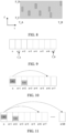
- UE1 sends to UE2 a transmission resource set (a resource set for short), which is resources within a time range [T_A, T_B] and a frequency domain range [F_C, F_D], as shown in FIG. 8 .
- UE1 sends the resource set to UE2
- both UE1 and UE2 need to have the same understanding of the resource set, and can determine that the resource set is transmission resources belonging to the time range [T_A, T_B] and the frequency domain range [F_C, F_D], that is, both UE1 and UE2 can determine T_A, T_B, F_C and F_D.
- T_A and T_B represent a time domain location or a slot index corresponding to the time domain location
- F_C and F_D represent a frequency domain location, such as Physical Resource Block (PRB) index or sub-channel index.
- PRB Physical Resource Block
- Example 1 The starting location T_A and/or ending location T_B of the time window is sent to UE2 by UE1.
- T_A or T_B may be simultaneously sent to UE2, so that UE1 and UE2 may determine the same T_A and T_B.
- the indication information for determining T_A or T_B may be carried by SCI, MAC CE, MAC PDU, PC5-RRC signaling or the like.
- Example 2 The starting location T_A of the time window is determined by a location of a slot in which the UE1 sends the sidelink channel carrying the resource set.
- the resource set is carried on a sidelink channel, such as carried in an SCI, a PC5-RRC, a MAC CE, or a MAC PDU.
- UE1 sends indication information of the resource set in slot n, and both UE1 and UE2 can determine time location T_A according to slot n.
- the time location T_A may be the kth slot after slot n, i.e. slot n+k, where k is an integer greater than or equal to 1.
- k may be determined from pre-configuration information, network configuration information, resource pool configuration information, indication information of UE2. Or, k can be a fixed value. Or, k may be determined according to a processing capability of the terminal, referring to example 5 below. If a processing delay or preparation time of the terminal is Tproc, the time location T_A is the first available slot after the time location Tn + Tproc, or Tn+1 + Tproc. Tn and Tn+1 represent time locations corresponding to slot n and slot n+1 respectively, and Tproc may be expressed without the unit of slot, for example, may be expressed by the unit of time domain symbol.
- UE1 sends a sidelink channel to UE2 in slot n, and the sidelink channel includes a resource set.
- Example 3 The starting location T_A and/or ending location T_B of the time window is determined by information sent to UE1 by UE2.
- Example 3-1 UE2 sends information to UE1, including information for determining the starting location T_A of the time window.
- Example 3-1-1 the indication information includes time domain location indication information, and the time domain location indication information is used for determining the starting location T_A and/or the ending location T_B of the time window.
- UE2 sends indication information to UE1 in slot n, the indication information is used for determining that the starting location T_A of the time window is slot n+6, and UE1 sends the resource set to UE2 in slot n+2, the starting location of the time window of the resource set is slot n+6.
- Example 3-1-2 the indication information includes indication information of a resource selection window, the UE1 determines the starting location T_A and/or the ending location T_B of the time window according to the indication information of the resource selection window.
- UE2 sends indication information to UE1 in slot n, the indication information is used for determining that the starting location of the resource selection window is slot n+6 and the ending location is slot n+20.
- the UE1 sends the resource set to the UE2 in the slot n+2, and the resources in the resource selection window of the resource set, i.e. the starting location T_A of the time window is the slot n+6, and the ending location T_B is the slot n+20.
- Example 3-1-3 the indication information includes indication information of a resource reservation period of the UE2, the starting location T_A and/or the ending location T_B of the time window are determined according to the indication information.
- the indication information of the resource reservation period P is carried in SCI
- the indication information is used to indicate that UE2 reserves transmission resources after period P
- the resource set is transmission resources within the time window [T_A, T_B], the starting location T_A of the time window is, for example, slot n+10, or, slot n+10-k, where k is an integer.
- the ending location T_B of the time window can be determined.
- the SCI when UE2 sends sidelink data in slot n, the SCI carries the resource reservation period P, and the SCI indicates that resources in slot n + a are reserved, or that resources in slot n + b and slot n + a are reserved.
- one SCI can indicate up to 3 resources (i.e. slot n, slot n + b, slot n + a), slot n + a is located after slot n + b.
- UE2 simultaneously reserves transmission resources after one period, that is, the resources in slots n + P, n + P + b and n + P + a.
- the ending location of the time window in which the resource set is located can be determined as slot n + P + a, n+2P or n+2P-1.
- UE1 sends the resource set to UE2 in slot n+8.
- the resources in the resource set may be transmission resources located within slots [n+10, n+20], or may be transmission resources located within slots [n+10, n+19], or may be transmission resources located within slots [n+10, n+15].
- Example 4 The length T_L of the time window is obtained, and the ending location T_B of the time window is determined according to the starting location T_A of the time window, or the starting location T_A of the time window is determined according to the ending location B of the time window.
- Example 4-1 The length of the time window can be pre-configured or specified by a protocol.
- the length of the time window is 100ms, 100 slots or 32 slots, etc.
- Example 4-2 The length of the time window can be configured by the network.
- the network configures this parameter through System Information Block (SIB) information or RRC signaling.
- SIB System Information Block
- RRC Radio Resource Control
- the length of the time window is a resource pool configuration parameter. For example, in a pre-configured or network-configured resource pool, a parameter for determining the length of the time window is included.
- the parameter T_L for the length of the time window is included in the resource pool configuration information, and the length of the time window can be determined according to this parameter.
- a set of available resource reservation period parameters ⁇ P1, P2, P3, ... ⁇ is included in the resource pool configuration information, and the length of the time window is determined according to the set.
- the length of the time window is the minimum or maximum value in the set.
- Example 4-4 The length of the time window can be determined according to information sent by UE2.
- UE2 sends information to UE1, the information includes a packet delay budget (PDB), the length of the time window is determined according to the PDB.
- PDB packet delay budget
- the UE2 sends information to the UE1, and the information is used for indicating a time length or a quantity of slots.
- the length of the time window is determined according to the time length or the quantity of slots.
- the information sent by the UE2 includes an index value, and the length of the time window is determined according to the index value and a first corresponding relationship.
- the first corresponding relationship is a corresponding relationship between the index value and the length of the time window.
- the first corresponding relationship can be pre-configured, network configured, or sent from UE1 to UE2, or sent from UE2 to UE1 when UE1 and UE2 establish a communication link.
- Example 5 On the basis of the above example, the starting location T_A and/or the ending location T_B of the time window are further determined according to a processing delay or a processing time of the terminal.
- the following are several examples of the method for determining a starting location F_C of the frequency domain and an ending location F_D of the frequency domain.
- Example 6 Determining the location range of the frequency domain F_C and/or F_D of the transmission resource set according to resource pool configuration information.
- the UE1 acquires the resource pool configuration information and determines the starting location F_C and/and the ending location F_D of the frequency domain corresponding to the resource pool according to the resource pool configuration information.
- the resource pool configuration information includes the index of the initial sub-channel, the size of the sub-channel and the quantity of the sub-channels of the resource pool.
- the starting location and ending location of frequency domain of the resource pool can be determined according to these three parameters.
- Example 7 Determining the location range of the frequency domain according to the information of UE2.
- the UE2 sends indication information to the UE1, and the UE1 determines the starting location and/or the ending location of the frequency domain according to the indication information.
- UE1 when UE1 determines the resource set, it can be determined by sensing. Since the resource set is used for UE2 to select a resource, UE1 can perform sensing in the sending resource pool of UE2 when sensing for resources. Therefore, UE2 needs to send information of the sending resource pool to UE1. Thus the UE1 can determine the starting location and the ending location of the frequency domain resource in the manner of example 6.
- the UE2 sends indication information to the UE1, and the indication information is used for determining the starting location and the ending location of the frequency domain.
- the UE1 can determine the starting location and the ending location of the frequency domain according to the indication information.
- the UE2 sends indication information to the UE1, and the indication information is used for determining the starting location of the frequency domain and the length of the frequency domain.
- the UE1 can determine the starting location and the ending location of the frequency domain according to the indication information.
- the length of the frequency domain is, for example, the quantity of PRBs or the quantity of sub-channels.
- the UE2 sends indication information to the UE1, and the indication information is used for determining the starting location of the frequency domain.
- the UE1 can determine the starting location of the frequency domain according to the indication information. Further, the UE1 determines the length of the frequency domain, and thus the ending location of the frequency domain can be determined.
- the length of the frequency domain is determined by the UE1, including at least one of the following manners:
- Example 8 Determining the location range of the frequency domain according to the pre-configuration information or the protocol stipulation. For example, the size or range of the frequency domain can be determined in the manner of the protocol stipulation.
- the resource set sent to UE2 by UE1, or the indication information sent to UE1 by UE2, may be carried in SCI, PC5-RRC signaling, MAC CE, or MAC PDU.
- the time domain location and the frequency domain location of the resource window of the transmission resource set sent by the sending end to the receiving end can be determined, so that the sending end and the receiving end of the resource set can determine the same time-frequency range.
- FIG. 13 is a schematic block diagram of a first terminal 400 according to an embodiment of the present application.
- the first terminal 400 may include: a sending unit 410, used for sending a transmission resource set to a second terminal, wherein a transmission resource included in the transmission resource set belongs to transmission resources in a first time-frequency range.
- the first time-frequency range includes a starting location of a time domain and/or an ending location of a time domain.
- the starting location of the time domain and/or the ending location of the time domain are determined based on first indication information sent by the first terminal.
- the first indication information is carried in SCI, MAC CE, MAC PDU or PC5-RRC signaling.
- the first indication information and the set of transmission resources are carried in the same sidelink channel.
- the starting location of the time domain and/or the ending location of the time domain are determined based on a location of a slot in which the sidelink channel carrying the transmission resource set is located.
- the starting location of the time domain and/or the ending location of the time domain are determined based on the location of the slot in which the sidlink channel carrying the transmission resource set and a time length corresponding to a terminal processing capability.
- the time length corresponding to the terminal processing capability is expressed by a quantity of time domain symbols.
- the time length corresponding to the terminal processing capability is determined according to a sub-carrier spacing of a bandwidth part in which the sidelink channel carrying the transmission resource set is located.
- the time length corresponding to the terminal processing capability includes:
- the starting location of the time domain and/or the ending location of the time domain are determined based on the location of the slot in which the sidelink channel carrying the transmission resource set and a time offset.
- the time offset is determined based on at least one of the following:
- the starting location of the time domain and/or the ending location of the time domain are determined based on third indication information of the second terminal.
- the third indication information includes time domain location indication information, and the time domain location indication information includes the starting location of the time domain and/or the ending location of the time domain.
- the third indication information includes indication information of a resource selection window, and the indication information of the resource selection window includes at least one of the following:
- the starting location of the time domain is determined according to the starting location of the resource selection window.
- the ending location of the time domain is determined according to the ending location of the resource selection window.
- the third indication information includes information of a resource reservation period.
- the starting location of the time domain and/or the ending location of the time domain are determined based on the resource reservation period and a location of a slot in which the sidelink channel carrying the third indication information is located.
- the starting location of the time domain and/or the ending location of the time domain are determined based on the resource reservation period, a reserved slot of the second terminal and the location of the slot in which the sidelink channel carrying the third indication information is located.
- the starting location of the time domain and/or the ending location of the time domain are determined based on a length of the time domain.
- the length of the time domain is determined based on at least one of the following:
- the fourth indication information includes a packet delay budget (PDB), the length of the time domain is determined based on the PDB.
- PDB packet delay budget
- the fourth indication information includes a time length or a quantity of slots, and the length of the time domain is determined based on the time length or the quantity of slots.
- the fourth indication information includes an index value, and the length of the time domain is determined based on the index value and a first corresponding relationship.
- the first corresponding relationship is pre-configured, network configured, or determined based on fifth indication information of the second terminal.
- the first time-frequency range includes a starting location of the frequency domain and/or an ending location of the frequency domain.
- the starting location of the frequency domain and/or the ending location of the frequency domain are determined based on resource pool configuration information.
- the resource pool configuration information includes at least one of the following: an index of an initial sub-channel, a size of a sub-channel and a quantity of sub-channels of the resource pool.
- the starting location of the frequency domain and/or the ending location of the frequency domain are determined based on sixth indication information of the second terminal.
- the sixth indication information includes the resource pool configuration information.
- the sixth indication information includes the starting location of the frequency domain and the ending location of the frequency domain.
- the sixth indication information includes the starting location of the frequency domain and a length of the frequency domain; the ending location of the frequency domain is determined by the first terminal based on the starting location of the frequency domain and the length of the frequency domain.
- the sixth indication information includes the ending location of the frequency domain and a length of the frequency domain; the starting location of the frequency domain is determined by the first terminal based on the ending location of the frequency domain and the length of the frequency domain.
- the sixth indication information includes the starting location of the frequency domain; the ending location of the frequency domain is determined by the first terminal based on the starting location of the frequency domain and a length of the frequency domain.
- the sixth indication information includes the ending location of the frequency domain; the starting location of the frequency domain is determined by the first terminal based on the ending location of the frequency domain and a length of the frequency domain.
- the length of the frequency domain is determined based on at least one of the following:
- the starting location of the frequency domain and/or the ending location of the frequency domain are determined based on the pre-configuration information or the protocol stipulation.
- the first terminal 400 of the embodiment of the present application can realize the corresponding function of the first terminal in the aforementioned method embodiments.
- the flow, function, implementation mode and beneficial effect corresponding to each module (sub-module, unit or component, etc.) in the first terminal 400 can be referred to the corresponding description in the above method embodiments, and will not be repeated here.
- the functions described with respect to each module (sub-module, unit, component, etc.) in the first terminal 400 of the embodiment of the present application may be realized by different modules (sub-module, unit, component, etc.) or by the same module (sub-module, unit, component, etc.).
- FIG. 14 is a schematic block diagram of a second terminal 500 according to an embodiment of the present application.
- the second terminal 500 may include: a receiving unit 510, used for receiving a transmission resource set from a first terminal, wherein a transmission resource included in the transmission resource set belongs to transmission resources in a first time-frequency range.
- the first time-frequency range includes a starting location of a time domain and/or an ending location of a time domain.
- the starting location of the time domain and/or the ending location of the time domain are determined based on first indication information from the first terminal.
- the first indication information is carried in SCI, MAC CE, MAC PDU or PC5-RRC signaling.
- the first indication information and the transmission resource set are carried in the same sidelink channel.
- the starting location of the time domain and/or the ending location of the time domain are determined based on a location of a slot in which the sidelink channel carrying the transmission resource set is located.
- the starting location of the time domain and/or the ending location of the time domain are determined based on the location of the slot in which the sidelink channel carrying the transmission resource set is located and a time length corresponding to a terminal processing capability.
- the time length corresponding to the terminal processing capability is expressed by a quantity of time domain symbols.
- the time length corresponding to the terminal processing capability is determined according to a sub-carrier spacing of a bandwidth part in which the sidelink channel carrying the transmission resource set is located.
- the time length corresponding to the terminal processing capability includes:
- the starting location of the time domain and/or the ending location of the time domain are determined based on the location of the slot in which the sidelink channel carrying the transmission resource set and a time offset.
- the time offset is determined based on at least one of the following:
- the starting location of the time domain and/or the ending location of the time domain are determined based on third indication information of the second terminal.
- the third indication information includes time domain location indication information, and the time domain location indication information includes the starting location of the time domain and/or the ending location of the time domain.
- the third indication information includes indication information of a resource selection window, and the indication information of the resource selection window includes at least one of the following:
- the starting location of the time domain is determined according to the starting location of the resource selection window.
- the ending location of the time domain is determined according to the ending location of the resource selection window.
- the third indication information includes information of a resource reservation period.
- the starting location of the time domain and/or the ending location of the time domain are determined based on the resource reservation period and a location of a slot in which a sidelink channel carrying the third indication information is located.
- the starting location of the time domain and/or the ending location of the time domain are determined based on the resource reservation period, a reserved slot of the second terminal and the location of the slot in which the sidelink channel carrying the third indication information is located.
- the starting location of the time domain and/or the ending location of the time domain are determined based on a length of the time domain.
- the length of the time domain is determined based on at least one of the following:
- the fourth indication information includes a packet delay budget (PDB), the length of the time domain is determined based on the PDB.
- PDB packet delay budget
- the fourth indication information includes a time length or a quantity of slots, the length of the time domain is determined based on the time length or the quantity of slots.
- the fourth indication information includes an index value, and the length of the time domain is determined based on the index value and a first corresponding relationship.
- the first corresponding relationship is pre-configured, network configured, or determined based on fifth indication information of the second terminal.
- the first time-frequency range includes a starting location of a frequency domain and/or an ending location of a frequency domain.
- the starting location of the frequency domain and/or the ending location of the frequency domain are determined based on the resource pool configuration information.
- the resource pool configuration information includes at least one of the following: an index of an initial sub-channel, a size of a sub-channel and a quantity of sub-channels of the resource pool.
- the starting location of the frequency domain and/or the ending location of the frequency domain are determined based on sixth indication information of the second terminal.
- the sixth indication information includes the resource pool configuration information.
- the sixth indication information includes the starting location of the frequency domain and the ending location of the frequency domain.
- the sixth indication information includes the starting location of the frequency domain and a length of the frequency domain; the ending location of the frequency domain is determined by the second terminal based on the starting location of the frequency domain and the length of the frequency domain.
- the sixth indication information includes the ending location of the frequency domain and a length of the frequency domain; the starting location of the frequency domain is determined by the second terminal based on the ending location of the frequency domain and the length of the frequency domain.
- the sixth indication information includes the starting location of the frequency domain; the ending location of the frequency domain is determined by the second terminal based on the starting location of the frequency domain and a length of the frequency domain.
- the sixth indication information includes the ending location of the frequency domain; the starting location of the frequency domain is determined by the second terminal based on the ending location of the frequency domain and a length of the frequency domain.
- the length of the frequency domain is determined based on at least one of pre-configuration information
- the starting location of the frequency domain and/or the ending location of the frequency domain are determined based on the pre-configuration information or the protocol stipulation.
- the second terminal 500 of the embodiment of the present application can realize the corresponding functions of the second terminal in the aforementioned method embodiments.
- the flow, function, implementation mode and beneficial effect corresponding to each module (sub-module, unit or component, etc.) in the second terminal 500 can be referred to the corresponding description in the above method embodiments, and will not be repeated here.
- the functions described with respect to each module (sub-module, unit, component, etc.) in the second terminal 500 of the embodiment of the present application may be realized by different modules (sub-module, unit, component, etc.) or by the same module (sub-module, unit, component, etc.).
- FIG. 15 is a schematic diagram of a structure of a communication device 600 according to an embodiment of the present application.
- the communication device 600 includes a processor 610.
- the processor 610 may call and run a computer program from a memory to enable the communication device 600 to implement the method in the embodiments of the present application.
- the communication device 600 may further include a memory 620.
- the processor 610 may call and run the computer program from the memory 620 to enable the communication device 600 to implement the method in the embodiments of the present application.
- the memory 620 may be a separate device independent of the processor 610 or may be integrated in the processor 610.
- the communication device 600 may further include a transceiver 630, and the processor 610 may control the transceiver 630 to communicate with another device. Specifically, information or data may be sent to another device, or information or data sent by another device may be received.
- the transceiver 630 may include a transmitter and a receiver.
- the transceiver 630 may further include antennas, the quantity of which may be one or more.
- the communication device 600 may specifically be the network device of the embodiments of the present application, and the communication device 600 may implement corresponding processes implemented by the network device in various methods of the embodiments of the present application, which will not be repeated here for brevity.
- the communication device 600 may be the terminal device of the embodiments of the present application, such as the first terminal or the second terminal, and the communication device 600 may perform corresponding processes implemented by the terminal device in various methods of the embodiments of the present application, which will not be repeated here again for brevity.
- FIG. 16 is a schematic diagram of a structure of a chip 700 according to an embodiment of the present application.
- the chip 700 includes a processor 710.
- the processor 710 may call and run a computer program from a memory to implement the method in the embodiments of the present application.
- the chip 700 may further include a memory 720.
- the processor 710 may call and run the computer program from the memory 720 to implement the method executed by the terminal device or a network device in embodiments of the present application.
- the memory 720 may be a separate device independent of the processor 710 or may be integrated in the processor 710.
- the chip 700 may further include an input interface 730.
- the processor 710 may control the input interface 730 to communicate with other devices or chips, and specifically, may acquire information or data sent by other devices or chips.
- the chip 700 may further include an output interface 740.
- the processor 710 may control the output interface 740 to communicate with other devices or chips, and specifically, may output information or data to other devices or chips.
- the chip may be applied to the network device in the embodiment of the present application, and the chip may implement the corresponding processes implemented by the network device in various methods in the embodiments of the present application, which will not be repeated herein for brevity.
- the chip may be applied to the terminal device in the embodiment of the present application, and the chip may implement the corresponding processes implemented by the terminal device in the various methods in the embodiments of the present application, which will not be repeated herein for brevity.
- the chips applied to the network device and the terminal device may be the same chip or different chips.
- chip mentioned in the embodiments of the present application may also be referred to as a system-level chip, a system chip, a chip system, or a system on chip, etc.
- the processor above-mentioned may be a general purpose processor, a digital signal processor (DSP), a field programmable gate array (FPGA), an application specific integrated circuit (ASIC) or other programmable logic devices, a transistor logic device, or a discrete hardware component, etc.
- DSP digital signal processor
- FPGA field programmable gate array
- ASIC application specific integrated circuit
- the above-mentioned general-purpose processor may be a microprocessor or any conventional processor, etc.
- the above-mentioned memory may be a volatile memory or non-volatile memory, or may include both volatile and non-volatile memories.
- the non-volatile memory may be a read-only memory (ROM), a programmable ROM (PROM), an erasable PROM (EPROM), an electrically erasable EPROM (EEPROM), or a flash memory.
- the volatile memory may be a Random Access Memory (RAM).
- the above-mentioned memories are examples for illustration and should not be construed as limitations.
- the memory in the embodiments of the present application may be a Static RAM (SRAM), a Dynamic RAM (DRAM), a Synchronous DRAM (SDRAM), a Double Data Rate SDRAM (DDR SDRAM), an Enhanced SDRAM (ESDRAM), a Synch Link DRAM (SLDRAM), a Direct Rambus RAM (DR RAM), etc. That is to say, the memories in the embodiments of the present application are intended to include, but are not limited to, these and any other suitable types of memories.
- FIG. 17 is a schematic block diagram of a communication system 800 according to an embodiment of the present application.
- the communication system 8000 includes: a first terminal 810 and a second terminal 820.
- the first terminal is used for sending a transmission resource set to the second terminal, wherein a transmission resource included in the transmission resource set belongs to transmission resources in a first time-frequency range.
- the second terminal is used for receiving the transmission resource set from the first terminal.
- the first terminal 810 may be used for performing the corresponding functions implemented by the first terminal in the above methods
- the second terminal 820 may be used for performing the corresponding functions implemented by the second terminal in the above methods, which will not be repeated here again for brevity.
- the above-mentioned embodiments can be implemented in whole or in part through software, hardware, firmware, or any combination thereof.
- When implemented through software they can be implemented in whole or in part in the form of a computer program product.
- the computer program product includes one or more computer instructions. When the computer program instructions are loaded and executed on a computer, flows or functions in accordance with the embodiments of the present application are generated in whole or in part.
- the computer may be a general purpose computer, a special purpose computer, a computer network, or another programmable apparatus.
- the computer instructions may be stored in a computer-readable storage medium, or transmitted from one computer-readable storage medium to another computer-readable storage medium, for example, the computer instructions may be transmitted from a website site, a computer, a server, or a data center to another website site, computer, server, or data center through a wired mode (e.g., a coaxial cable, an optical fiber, a Digital Subscriber Line (DSL)) or a wireless mode (e.g., infrared radiation, radio, microwave, etc.).
- a wired mode e.g., a coaxial cable, an optical fiber, a Digital Subscriber Line (DSL)
- a wireless mode e.g., infrared radiation, radio, microwave, etc.
- the computer-readable storage medium may be any available medium that can be accessed by a computer or a data storage device such as a server, a data center, or the like that integrates one or more available media.
- the available media may be magnetic media (e.g., a floppy disk, a hard disk, a magnetic tape), optical media (e.g., a Digital Versatile Disk, (DVD)), or semiconductor media (e.g., a Solid State Disk (SSD)), or the like.
Landscapes
- Engineering & Computer Science (AREA)
- Signal Processing (AREA)
- Computer Networks & Wireless Communication (AREA)
- Quality & Reliability (AREA)
- Databases & Information Systems (AREA)
- Physics & Mathematics (AREA)
- Mathematical Physics (AREA)
- Mobile Radio Communication Systems (AREA)
- Time-Division Multiplex Systems (AREA)
Applications Claiming Priority (1)
| Application Number | Priority Date | Filing Date | Title |
|---|---|---|---|
| PCT/CN2020/117951 WO2022061790A1 (zh) | 2020-09-25 | 2020-09-25 | 资源集合的传输方法和终端 |
Publications (2)
| Publication Number | Publication Date |
|---|---|
| EP4203580A1 true EP4203580A1 (de) | 2023-06-28 |
| EP4203580A4 EP4203580A4 (de) | 2023-10-04 |
Family
ID=80844791
Family Applications (1)
| Application Number | Title | Priority Date | Filing Date |
|---|---|---|---|
| EP20954642.3A Pending EP4203580A4 (de) | 2020-09-25 | 2020-09-25 | Ressourcensatzübertragungsverfahren und endgeräte |
Country Status (8)
| Country | Link |
|---|---|
| US (2) | US12538332B2 (de) |
| EP (1) | EP4203580A4 (de) |
| JP (1) | JP7668346B2 (de) |
| KR (1) | KR20230074503A (de) |
| CN (2) | CN116321456B (de) |
| AU (1) | AU2020469301B2 (de) |
| BR (1) | BR112023005390A2 (de) |
| WO (1) | WO2022061790A1 (de) |
Families Citing this family (4)
| Publication number | Priority date | Publication date | Assignee | Title |
|---|---|---|---|---|
| CN115004732B (zh) * | 2022-04-18 | 2025-06-06 | 北京小米移动软件有限公司 | 一种基于辅助资源集进行通信的方法、装置及存储介质 |
| CN119012386A (zh) * | 2023-05-21 | 2024-11-22 | 华为技术有限公司 | 数据传输方法和通信装置 |
| CN121057008A (zh) * | 2024-05-24 | 2025-12-02 | 中信科智联科技有限公司 | 一种确定传输资源的方法、装置及终端 |
| WO2026065496A1 (zh) * | 2024-09-30 | 2026-04-02 | Oppo广东移动通信有限公司 | 资源确定方法、装置、设备、介质和程序产品 |
Family Cites Families (21)
| Publication number | Priority date | Publication date | Assignee | Title |
|---|---|---|---|---|
| US9942917B2 (en) * | 2015-05-14 | 2018-04-10 | Blackberry Limited | Allocating resources for a device-to-device transmission |
| ES3023752T3 (en) | 2016-04-11 | 2025-06-03 | Ntt Docomo Inc | User equipment and signal transmission method |
| US10966279B2 (en) | 2016-10-07 | 2021-03-30 | Apple Inc. | Multiple radio resource reservation for vehicle-to-everything communications |
| US10251158B2 (en) * | 2017-03-24 | 2019-04-02 | Qualcomm, Incorporated | Low latency enhancements to CV2X autonomous resource selection and re-selection procedure for vehicle-to-vehicle communications |
| US10952266B2 (en) | 2018-01-30 | 2021-03-16 | Hyundai Motor Company | Method for transmitting and receiving control information including configuration information for transmission and reception in communication system supporting vehicle-to-everything communication and apparatus for the same |
| WO2019178749A1 (zh) * | 2018-03-20 | 2019-09-26 | Oppo广东移动通信有限公司 | 资源共享的方法和终端设备 |
| CN110545524B (zh) * | 2018-05-28 | 2021-06-22 | 华为技术有限公司 | 资源分配方法以及通信设备 |
| CN112205071A (zh) | 2018-07-05 | 2021-01-08 | Oppo广东移动通信有限公司 | 控制信息的传输方法及资源池配置方法、装置、通信设备 |
| CN113015130B (zh) * | 2018-07-05 | 2023-03-24 | Oppo广东移动通信有限公司 | 一种车联网中传输数据的方法、终端设备、芯片和存储介质 |
| WO2020014985A1 (zh) * | 2018-07-17 | 2020-01-23 | Oppo广东移动通信有限公司 | 侧行链路中数据传输的方法和终端设备 |
| US20210329648A1 (en) | 2018-09-11 | 2021-10-21 | Ntt Docomo, Inc. | User equipment and base station apparatus |
| WO2020056696A1 (zh) * | 2018-09-20 | 2020-03-26 | Oppo广东移动通信有限公司 | 一种资源分配方法及装置、终端 |
| CN110958096B (zh) * | 2018-09-27 | 2021-09-28 | 大唐移动通信设备有限公司 | 一种资源指示方法及终端 |
| CN111148226B (zh) * | 2018-11-02 | 2022-05-31 | 北京紫光展锐通信技术有限公司 | 边链路传输方法、终端及计算机可读存储介质 |
| CN110536449B (zh) * | 2019-08-16 | 2025-08-05 | 中兴通讯股份有限公司 | 无线通信资源指示方法、装置和系统 |
| CN111246426B (zh) * | 2020-01-16 | 2023-07-04 | 北京紫光展锐通信技术有限公司 | 辅链路通信的资源选择方法及通信装置 |
| WO2021203248A1 (zh) * | 2020-04-07 | 2021-10-14 | 北京小米移动软件有限公司 | 唤醒时间控制方法、装置及计算机可读存储介质 |
| WO2021207459A1 (en) * | 2020-04-10 | 2021-10-14 | Convida Wireless, Llc | Sidelink enhancements - resource allocation assistance information |
| WO2022027246A1 (en) * | 2020-08-04 | 2022-02-10 | Telefonaktiebolaget Lm Ericsson (Publ) | Adaptive sensing based resource selection for d2d communication |
| JP7559218B2 (ja) * | 2020-08-07 | 2024-10-01 | 華為技術有限公司 | 通信方法、装置及びシステム |
| US12262368B2 (en) * | 2020-08-07 | 2025-03-25 | Qualcomm Incorporated | Timeline for sidelink inter-user equipment coordination |
-
2020
- 2020-09-25 CN CN202310312677.8A patent/CN116321456B/zh active Active
- 2020-09-25 CN CN202080103153.2A patent/CN116058028A/zh active Pending
- 2020-09-25 EP EP20954642.3A patent/EP4203580A4/de active Pending
- 2020-09-25 KR KR1020237012191A patent/KR20230074503A/ko active Pending
- 2020-09-25 JP JP2023518320A patent/JP7668346B2/ja active Active
- 2020-09-25 BR BR112023005390A patent/BR112023005390A2/pt unknown
- 2020-09-25 WO PCT/CN2020/117951 patent/WO2022061790A1/zh not_active Ceased
- 2020-09-25 AU AU2020469301A patent/AU2020469301B2/en active Active
-
2023
- 2023-03-08 US US18/180,214 patent/US12538332B2/en active Active
-
2025
- 2025-12-16 US US19/421,882 patent/US20260107292A1/en active Pending
Also Published As
| Publication number | Publication date |
|---|---|
| US12538332B2 (en) | 2026-01-27 |
| EP4203580A4 (de) | 2023-10-04 |
| KR20230074503A (ko) | 2023-05-30 |
| AU2020469301A1 (en) | 2023-05-18 |
| CN116321456B (zh) | 2024-12-06 |
| CN116058028A (zh) | 2023-05-02 |
| US20260107292A1 (en) | 2026-04-16 |
| WO2022061790A1 (zh) | 2022-03-31 |
| US20230224928A1 (en) | 2023-07-13 |
| CN116321456A (zh) | 2023-06-23 |
| AU2020469301A9 (en) | 2024-02-08 |
| AU2020469301B2 (en) | 2025-12-11 |
| JP7668346B2 (ja) | 2025-04-24 |
| JP2023547593A (ja) | 2023-11-13 |
| BR112023005390A2 (pt) | 2023-04-25 |
Similar Documents
| Publication | Publication Date | Title |
|---|---|---|
| US12538332B2 (en) | Resource set transmission method, and terminals | |
| US11895676B2 (en) | Resource set transmission method and terminal device | |
| CN116347601A (zh) | 无线通信的方法和终端设备 | |
| EP4142413A1 (de) | Sidelink-feedbackverfahren und endgerätevorrichtung | |
| US20230232375A1 (en) | Method for determining resource set and terminal device | |
| CN116347602B (zh) | 确定侧行链路配置授权资源的方法和终端设备 | |
| US20230354269A1 (en) | Wireless communication method and terminal device | |
| CN116326187A (zh) | 基于非连续接收的侦听方法和终端 | |
| US12526774B2 (en) | Sidelink resource indication information determination method, first terminal device, and second terminal device | |
| CN117136568A (zh) | 无线通信的方法和终端设备 | |
| KR20230017179A (ko) | 데이터 송신 방법, 단말 장치 및 네트워크 장치 | |
| WO2023122905A1 (zh) | 无线通信的方法及终端设备 | |
| WO2023279399A1 (zh) | 侧行传输资源的确定方法、发送方法、装置、设备及介质 | |
| EP4395376B1 (de) | Drahtloskommunikationsverfahren und endgerätevorrichtung | |
| CN119052923A (zh) | 无线通信的方法及终端设备 |
Legal Events
| Date | Code | Title | Description |
|---|---|---|---|
| STAA | Information on the status of an ep patent application or granted ep patent |
Free format text: STATUS: THE INTERNATIONAL PUBLICATION HAS BEEN MADE |
|
| PUAI | Public reference made under article 153(3) epc to a published international application that has entered the european phase |
Free format text: ORIGINAL CODE: 0009012 |
|
| STAA | Information on the status of an ep patent application or granted ep patent |
Free format text: STATUS: REQUEST FOR EXAMINATION WAS MADE |
|
| 17P | Request for examination filed |
Effective date: 20230322 |
|
| AK | Designated contracting states |
Kind code of ref document: A1 Designated state(s): AL AT BE BG CH CY CZ DE DK EE ES FI FR GB GR HR HU IE IS IT LI LT LU LV MC MK MT NL NO PL PT RO RS SE SI SK SM TR |
|
| REG | Reference to a national code |
Ref country code: DE Ref legal event code: R079 Free format text: PREVIOUS MAIN CLASS: H04W0072040000 Ipc: H04W0072250000 |
|
| A4 | Supplementary search report drawn up and despatched |
Effective date: 20230901 |
|
| RIC1 | Information provided on ipc code assigned before grant |
Ipc: H04W 72/25 20230101AFI20230828BHEP |
|
| DAV | Request for validation of the european patent (deleted) | ||
| DAX | Request for extension of the european patent (deleted) | ||
| STAA | Information on the status of an ep patent application or granted ep patent |
Free format text: STATUS: EXAMINATION IS IN PROGRESS |
|
| 17Q | First examination report despatched |
Effective date: 20251110 |