EP4204110B1 - Dispositif de traitement pour un ski - Google Patents
Dispositif de traitement pour un ski Download PDFInfo
- Publication number
- EP4204110B1 EP4204110B1 EP21761963.4A EP21761963A EP4204110B1 EP 4204110 B1 EP4204110 B1 EP 4204110B1 EP 21761963 A EP21761963 A EP 21761963A EP 4204110 B1 EP4204110 B1 EP 4204110B1
- Authority
- EP
- European Patent Office
- Prior art keywords
- ski
- support
- machining
- sidewalls
- tool
- Prior art date
- Legal status (The legal status is an assumption and is not a legal conclusion. Google has not performed a legal analysis and makes no representation as to the accuracy of the status listed.)
- Active
Links
Images

Classifications
-
- A—HUMAN NECESSITIES
- A63—SPORTS; GAMES; AMUSEMENTS
- A63C—SKATES; SKIS; ROLLER SKATES; DESIGN OR LAYOUT OF COURTS, RINKS OR THE LIKE
- A63C11/00—Accessories for skiing or snowboarding
- A63C11/04—Accessories for skiing or snowboarding for treating skis or snowboards
-
- B—PERFORMING OPERATIONS; TRANSPORTING
- B26—HAND CUTTING TOOLS; CUTTING; SEVERING
- B26D—CUTTING; DETAILS COMMON TO MACHINES FOR PERFORATING, PUNCHING, CUTTING-OUT, STAMPING-OUT OR SEVERING
- B26D3/00—Cutting work characterised by the nature of the cut made; Apparatus therefor
-
- A—HUMAN NECESSITIES
- A63—SPORTS; GAMES; AMUSEMENTS
- A63C—SKATES; SKIS; ROLLER SKATES; DESIGN OR LAYOUT OF COURTS, RINKS OR THE LIKE
- A63C11/00—Accessories for skiing or snowboarding
- A63C11/04—Accessories for skiing or snowboarding for treating skis or snowboards
- A63C11/06—Edge-sharpeners
-
- B—PERFORMING OPERATIONS; TRANSPORTING
- B23—MACHINE TOOLS; METAL-WORKING NOT OTHERWISE PROVIDED FOR
- B23D—PLANING; SLOTTING; SHEARING; BROACHING; SAWING; FILING; SCRAPING; LIKE OPERATIONS FOR WORKING METAL BY REMOVING MATERIAL, NOT OTHERWISE PROVIDED FOR
- B23D79/00—Methods, machines, or devices not covered elsewhere, for working metal by removal of material
- B23D79/02—Machines or devices for scraping
-
- B—PERFORMING OPERATIONS; TRANSPORTING
- B23—MACHINE TOOLS; METAL-WORKING NOT OTHERWISE PROVIDED FOR
- B23C—MILLING
- B23C3/00—Milling particular work; Special milling operations; Machines therefor
- B23C3/12—Trimming or finishing edges, e.g. deburring welded corners
-
- B—PERFORMING OPERATIONS; TRANSPORTING
- B26—HAND CUTTING TOOLS; CUTTING; SEVERING
- B26D—CUTTING; DETAILS COMMON TO MACHINES FOR PERFORATING, PUNCHING, CUTTING-OUT, STAMPING-OUT OR SEVERING
- B26D7/00—Details of apparatus for cutting, cutting-out, stamping-out, punching, perforating, or severing by means other than cutting
- B26D7/06—Arrangements for feeding or delivering work of other than sheet, web, or filamentary form
- B26D7/0625—Arrangements for feeding or delivering work of other than sheet, web, or filamentary form by endless conveyors, e.g. belts
Definitions
- the invention relates to a processing device for a ski with a support for the ski and a conveyor device for the ski in the longitudinal direction of the ski along the support.
- patent specification EP 1129748 A1 discloses such a device.
- the AT 413 651 B shows such a device for removing the sidewalls of a ski using a cutting edge that is arranged on a handle part provided with a guide surface.
- the handle part with the guide surface is placed on the running surface of the ski and moved by hand along the longitudinal edge of the ski, whereby the cutting edge removes the sidewall of the ski adjacent to the steel edge in order to make the steel edge more accessible for a subsequent grinding process.
- the invention is therefore based on the object of creating a processing device with the aid of which the sidewalls of a ski can be easily removed in a predetermined quality before edge grinding with a comparatively short expenditure of time.
- the invention solves the problem set by assigning to the support a device for processing the sidewalls of the ski with at least one cutting tool, which is arranged on a tool carrier that is adjustable transversely to the conveying direction and parallel to the support and can be adjusted to the sidewall to be processed of the ski conveyed along the support with the aid of a spring-loaded actuator for the tool carrier under a spring-loaded preload.
- this ski guide can be used advantageously for the device for machining the sidewalls because the support forms a structural reference specification for the device for machining the sidewalls, which is an essential prerequisite for precise guidance of the cutting tool in relation to the running surface distance.
- the longitudinal guidance of the cutting tool along the ski waist is automatically achieved during the ski conveyance in the longitudinal direction by the spring loading of the tool carrier transversely to the conveying direction of the ski.
- This transverse loading of the tool carrier which can be adjusted parallel to the support and transversely to the conveying direction, requires the cutting tool to be positioned against the sidewall of the ski with a predefined Setting force, whereby the sidewall or the steel edge itself guides the cutting tool during the ski feed. Due to the spring-loaded loading of the tool carrier across the sidewall of the ski, the device is also independent of the width and edge profile of the ski to be processed, so that the sidewalls of all possible types of skis, including snowboards, can be processed without having to extensively convert the processing device.
- the tool carrier could, for example, be provided on an arm that can be pivoted about an axis perpendicular to the ski support - simple, space-saving design conditions result if the device for machining the sidewalls of the ski has a frame with a guide rail running transversely to the conveying direction and parallel to the support for the tool carrier that can be driven by the spring-loaded actuator.
- the device for machining the sidewalls of the ski can advantageously comprise a frame with two tool carriers provided on both sides of the support, which can be moved transversely to the conveying direction and parallel to the support, each for a cutting tool, as well as an actuator for spring-loaded loading of the tool carriers.
- the simultaneous machining of both sidewalls of a ski not only has the advantage of shortening the machining time, but also simplifies the ski guidance between the cutting tools placed on the ski from opposite sides, so that the ski support that would otherwise be required on the side of the ski opposite the cutting tool is no longer necessary.
- the frame is mounted so that it can pivot between a working position and a maintenance position about a pivot axis parallel to the conveying direction, access to the cutting tools, but also to the equipment of the processing device in the area of the frame, can be easily provided.
- the spring-loaded preload of the cutting tool position can be adjusted by taking appropriate measures in the area of the actuating drives for the respective tool carrier. This is particularly advantageous if a pneumatic cylinder is provided as the actuating drive, although this is by no means mandatory.
- the choice of spring-loaded preload of the cutting tool position has a direct influence on the chip thickness of the chips to be removed from the sidewalls of the ski.
- the chips separated from the side wall contaminate the work area and can hinder the automated machining process. This can be avoided if the device includes at least one nozzle for removing the chips.
- the nozzle sprays rinsing fluid in the direction of the side wall so that the chips created by the cutting process are moved by the pressure of the rinsing fluid into an area provided for this purpose, for example a collecting basin. Air or water can advantageously be used as the rinsing fluid.
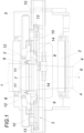
- the processing device shown for a ski 1 comprises a support 2 for the ski 1 in the form of a roller table and a conveyor device for the ski 1 in the longitudinal direction of the ski along the support 2.
- This ski guide is assigned to conventional tools for processing the steel edges or the running surface of the ski 1, but this is not shown for reasons of clarity.
- a new feature of this processing device is an additional device 3 for processing the side walls 4 of the ski 1.
- This device 3 has a frame 5 which comprises a guide rail 7 running transversely to the conveying direction 6 and parallel to the support 2 for two tool carriers 9, each of which holds a cutting tool 8.
- Spring-loaded actuating drives 10 engage the slide-like tool carriers 9, with the aid of which the cutting tools 8 are positioned under a spring-loaded preload against the side walls 4 of the ski 1 conveyed along the support 2 of the processing device. If the ski 1 is moved longitudinally relative to the device 3, the cutting tools 8 cut a chip from the side walls 4 of the ski 1 and thus expose the side edges of the steel edges of the ski 1 for better grinding.
- indexable inserts 11 are advantageously used, but this is not mandatory because it is only important to machine the side walls 4 of the ski 1 adjoining the steel edges, so that all suitable cutting tools, including driven milling cutters, could be used.
- the actuators 10 for the spring-loaded loading of the tool carriers 9 are designed as pneumatic cylinders, via which the contact force of the cutting tools 8 on the side walls 4 of the ski 1 can be adjusted depending on the respective requirements.
- at least one nozzle 12 for a flushing fluid can be provided for each side wall 4, with the aid of which the chips can be conveyed away from the ski area and removed.
- the device 3 can be used for sidewall machining of skis of different widths, including snowboards.
- the frame-fixed articulation points 13 of these pneumatic cylinders 11 can be adjusted in the adjustment direction.
- an actuator 14, for example an actuating cylinder, is provided for each of these articulation points 13.
- the frame 5 can be pivoted from the illustrated working position away from the support 2 into a maintenance position about an axis 15 aligned parallel to the conveying direction 6.
Landscapes
- Engineering & Computer Science (AREA)
- Mechanical Engineering (AREA)
- Life Sciences & Earth Sciences (AREA)
- Forests & Forestry (AREA)
- Physics & Mathematics (AREA)
- Optics & Photonics (AREA)
- Finish Polishing, Edge Sharpening, And Grinding By Specific Grinding Devices (AREA)
- Constituent Portions Of Griding Lathes, Driving, Sensing And Control (AREA)
- Sawing (AREA)
Claims (8)
- Dispositif d'affûtage pour ski (1) comprenant un support (2) pour le ski (1) présentant des bords en acier et un dispositif de transport pour le ski (1) dans la direction longitudinale du ski le long du support (2), caractérisé en ce qu'au support (2) est associé un moyen (3) destiné à affûter les carres (4) du ski (1) reliées aux bords en acier à l'aide d'au moins un outil de coupe (8) qui est disposé sur un porte-outil (9) dirigé de manière réglable transversalement à la direction de transport (6) et parallèlement au support (2) et peut être utilisé à l'aide d'un actionneur à ressort (10) pour le porte-outil (9) sous l'action d'une précontrainte à ressort sur la carre à affuter (4) du ski (1) transporté le long du support (2).
- Dispositif d'affûtage selon la revendication 1, caractérisé en ce que le moyen (3) destiné à affûter les carres (4) du ski(1) présente un châssis (5) avec un rail de guidage (7) s'étendant transversalement à la direction de transport (6) et parallèlement au support (2) pour le porte-outil (9) qui peut être entraîné par l'actionneur à ressort (10).
- Dispositif d'affûtage selon la revendication 1, caractérisé en ce que le moyen (3) destiné à affûter les carres (4) du ski (1) comprend un châssis (5) avec deux porte-outils (9) prévus des deux côtés du support (2) et pouvant être déplacés transversalement à la direction de transport (6) et parallèlement au support (2), pour un outil de coupe (8) à chaque fois, ainsi qu'un actionneur (10) pour la sollicitation à ressort du porte-outil (9).
- Dispositif d'affûtage selon la revendication 3, caractérisé en ce que le châssis (5) présente un rail de guidage (7) commun aux deux porte-outils (9), qui s'étend transversalement à la direction de transport (6) et parallèlement au support (2).
- Dispositif d'affûtage selon une des revendications 2 à 4, caractérisé en ce que le châssis (5) est monté pivotant, entre une position de travail et une position de maintenance, autour d'un axe de pivotement (15) parallèle à la direction de transport (6).
- Dispositif d'affûtage selon une des revendications 1 à 5, caractérisé en ce que la précontrainte à ressort pour l'utilisation de l'outil de coupe est réglable.
- Dispositif d'affûtage selon une des revendications 1 à 6, caractérisé en ce qu'un vérin pneumatique est prévu pour servir d'actionneur (10).
- Dispositif d'affutage selon une des revendications 1 à 7, caractérisé en ce que le moyen (3) présente au moins une buse (12) pour l'évacuation des copeaux produits lors de l'affûtage des carres.
Applications Claiming Priority (2)
| Application Number | Priority Date | Filing Date | Title |
|---|---|---|---|
| ATA50736/2020A AT523728B1 (de) | 2020-08-31 | 2020-08-31 | Bearbeitungsvorrichtung für einen Ski |
| PCT/AT2021/060289 WO2022040709A1 (fr) | 2020-08-31 | 2021-08-19 | Dispositif d'affutage pour ski |
Publications (3)
| Publication Number | Publication Date |
|---|---|
| EP4204110A1 EP4204110A1 (fr) | 2023-07-05 |
| EP4204110B1 true EP4204110B1 (fr) | 2025-03-05 |
| EP4204110C0 EP4204110C0 (fr) | 2025-03-05 |
Family
ID=77518856
Family Applications (1)
| Application Number | Title | Priority Date | Filing Date |
|---|---|---|---|
| EP21761963.4A Active EP4204110B1 (fr) | 2020-08-31 | 2021-08-19 | Dispositif de traitement pour un ski |
Country Status (4)
| Country | Link |
|---|---|
| US (1) | US20230330883A1 (fr) |
| EP (1) | EP4204110B1 (fr) |
| AT (1) | AT523728B1 (fr) |
| WO (1) | WO2022040709A1 (fr) |
Family Cites Families (9)
| Publication number | Priority date | Publication date | Assignee | Title |
|---|---|---|---|---|
| US5204987A (en) * | 1990-01-12 | 1993-04-20 | Hans Klingel | Apparatus for treating steel edges of skis and other runner devices |
| AT403805B (de) * | 1994-12-23 | 1998-05-25 | Fischer Gmbh | Verfahren zur bearbeitung von stahlkanten für ski od.dgl. |
| FR2805755B1 (fr) * | 2000-03-03 | 2002-11-22 | Skid Sa | Machine de traitement de skis a entrainement lateral |
| AT410525B (de) * | 2001-02-02 | 2003-05-26 | Wintersteiger Gmbh & Co | Vorrichtung zum bearbeiten der seitenkanten von skiern |
| AT413651B (de) * | 2002-12-04 | 2006-04-15 | Mitterberger Josef | Vorrichtung zum entfernen von material |
| EP1559451B1 (fr) * | 2004-01-30 | 2012-07-04 | Technolami S.R.L. - In Liquidazione | Ski avec carres en retrait par rapport à la semelle |
| AT413802B (de) * | 2004-01-30 | 2006-06-15 | Wintersteiger Gmbh & Co | Vorrichtung zum nachbearbeiten einer stahlkante eines skis |
| FR2958174B1 (fr) * | 2010-03-30 | 2012-04-06 | Jean Pierre Bocquet | Mecanisme d'affûtage de carres laterales de ski par disque abrasif a lamelles |
| CH705976A1 (de) * | 2012-01-10 | 2013-07-15 | Spuehl Ag | Anlage zur Bearbeitung von Laufflächen und den Kanten an Skiern und Snowboards. |
-
2020
- 2020-08-31 AT ATA50736/2020A patent/AT523728B1/de active
-
2021
- 2021-08-19 US US18/022,287 patent/US20230330883A1/en active Pending
- 2021-08-19 EP EP21761963.4A patent/EP4204110B1/fr active Active
- 2021-08-19 WO PCT/AT2021/060289 patent/WO2022040709A1/fr not_active Ceased
Also Published As
| Publication number | Publication date |
|---|---|
| EP4204110A1 (fr) | 2023-07-05 |
| EP4204110C0 (fr) | 2025-03-05 |
| US20230330883A1 (en) | 2023-10-19 |
| AT523728B1 (de) | 2021-11-15 |
| AT523728A4 (de) | 2021-11-15 |
| WO2022040709A1 (fr) | 2022-03-03 |
Similar Documents
| Publication | Publication Date | Title |
|---|---|---|
| DE3522278C2 (fr) | ||
| EP0237615B1 (fr) | Machine à scier et à percer pour le débitage et l'alésage de pièces en plaques | |
| AT412197B (de) | Vorrichtung zum bearbeiten von werkstoffplatten | |
| EP2147761A2 (fr) | Procédé de répartition de pièces usinées en forme de plaque de grand format et installation de répartition de plaques | |
| DE2523034B2 (de) | Vorrichtung zum automatischen buntaufteilen einer platte | |
| AT396890B (de) | Vorrichtung zum abstützen eines auf einer plattenaufteilsäge hergestellten langen und schmalen werkstückpakets | |
| DE2531133A1 (de) | Vorrichtung zur fortlaufenden bearbeitung der beiden seiten eines brillenglases | |
| EP1412120B1 (fr) | Systeme de coupe | |
| EP4008508A1 (fr) | Procédé de sciage d'au moins une plaque | |
| EP0361126A1 (fr) | Scie pour le débitage des plaques | |
| EP4204110B1 (fr) | Dispositif de traitement pour un ski | |
| DE3830856C1 (fr) | ||
| EP0602308A1 (fr) | Dispositif pour travailler les côtés de pièces en forme de plaques alimentées de façon continue | |
| DE102019219732A1 (de) | Anlage für Formatbearbeitungen, Kantenanleimungen und Bohrungen an Werkstücken aus Holz und dergleichen und entsprechendes Betriebsverfahren | |
| EP3475040B1 (fr) | Machine avec des zones de travail et méthode associée | |
| EP1685880B1 (fr) | Appareil pour travailler sur des skis équiper d'une fixation | |
| EP0489681B1 (fr) | Procédé et dispositif pour déplacer des pièces en forme de bandes ou de panneaux, empilés et juxtaposés sur une surface de support à faible coefficient de frottement | |
| DE3632018A1 (de) | Aufteilanlage fuer plattenfoermige werkstuecke | |
| DE10109007A1 (de) | Sägeanlage | |
| EP0362833A2 (fr) | Machine de travail du bois, de préférence une moulurière | |
| DE3417963C2 (fr) | ||
| CH665159A5 (de) | Schleifmaschine. | |
| EP0604702B1 (fr) | Dispositif pour trancher du bois équarri en planches | |
| EP0642865B1 (fr) | Dispositif pour le rognage des rives longitudinales de produits laminés en mouvement | |
| EP3684569B1 (fr) | Procédé de découpe d'une pièce de préférence en forme de panneau |
Legal Events
| Date | Code | Title | Description |
|---|---|---|---|
| STAA | Information on the status of an ep patent application or granted ep patent |
Free format text: STATUS: UNKNOWN |
|
| STAA | Information on the status of an ep patent application or granted ep patent |
Free format text: STATUS: THE INTERNATIONAL PUBLICATION HAS BEEN MADE |
|
| PUAI | Public reference made under article 153(3) epc to a published international application that has entered the european phase |
Free format text: ORIGINAL CODE: 0009012 |
|
| STAA | Information on the status of an ep patent application or granted ep patent |
Free format text: STATUS: REQUEST FOR EXAMINATION WAS MADE |
|
| 17P | Request for examination filed |
Effective date: 20230208 |
|
| AK | Designated contracting states |
Kind code of ref document: A1 Designated state(s): AL AT BE BG CH CY CZ DE DK EE ES FI FR GB GR HR HU IE IS IT LI LT LU LV MC MK MT NL NO PL PT RO RS SE SI SK SM TR |
|
| RAP3 | Party data changed (applicant data changed or rights of an application transferred) |
Owner name: WINTERSTEIGER HOLDING AG |
|
| RAP1 | Party data changed (applicant data changed or rights of an application transferred) |
Owner name: WINTERSTEIGER SPORTS GMBH |
|
| DAV | Request for validation of the european patent (deleted) | ||
| DAX | Request for extension of the european patent (deleted) | ||
| GRAP | Despatch of communication of intention to grant a patent |
Free format text: ORIGINAL CODE: EPIDOSNIGR1 |
|
| STAA | Information on the status of an ep patent application or granted ep patent |
Free format text: STATUS: GRANT OF PATENT IS INTENDED |
|
| RIC1 | Information provided on ipc code assigned before grant |
Ipc: A63C 11/06 20060101AFI20241115BHEP |
|
| INTG | Intention to grant announced |
Effective date: 20241128 |
|
| GRAS | Grant fee paid |
Free format text: ORIGINAL CODE: EPIDOSNIGR3 |
|
| GRAA | (expected) grant |
Free format text: ORIGINAL CODE: 0009210 |
|
| STAA | Information on the status of an ep patent application or granted ep patent |
Free format text: STATUS: THE PATENT HAS BEEN GRANTED |
|
| AK | Designated contracting states |
Kind code of ref document: B1 Designated state(s): AL AT BE BG CH CY CZ DE DK EE ES FI FR GB GR HR HU IE IS IT LI LT LU LV MC MK MT NL NO PL PT RO RS SE SI SK SM TR |
|
| REG | Reference to a national code |
Ref country code: GB Ref legal event code: FG4D Free format text: NOT ENGLISH |
|
| REG | Reference to a national code |
Ref country code: CH Ref legal event code: EP |
|
| REG | Reference to a national code |
Ref country code: DE Ref legal event code: R096 Ref document number: 502021006872 Country of ref document: DE |
|
| REG | Reference to a national code |
Ref country code: IE Ref legal event code: FG4D Free format text: LANGUAGE OF EP DOCUMENT: GERMAN |
|
| U01 | Request for unitary effect filed |
Effective date: 20250328 |
|
| U07 | Unitary effect registered |
Designated state(s): AT BE BG DE DK EE FI FR IT LT LU LV MT NL PT RO SE SI Effective date: 20250403 |
|
| PG25 | Lapsed in a contracting state [announced via postgrant information from national office to epo] |
Ref country code: RS Free format text: LAPSE BECAUSE OF FAILURE TO SUBMIT A TRANSLATION OF THE DESCRIPTION OR TO PAY THE FEE WITHIN THE PRESCRIBED TIME-LIMIT Effective date: 20250605 |
|
| PG25 | Lapsed in a contracting state [announced via postgrant information from national office to epo] |
Ref country code: ES Free format text: LAPSE BECAUSE OF FAILURE TO SUBMIT A TRANSLATION OF THE DESCRIPTION OR TO PAY THE FEE WITHIN THE PRESCRIBED TIME-LIMIT Effective date: 20250305 |
|
| PG25 | Lapsed in a contracting state [announced via postgrant information from national office to epo] |
Ref country code: NO Free format text: LAPSE BECAUSE OF FAILURE TO SUBMIT A TRANSLATION OF THE DESCRIPTION OR TO PAY THE FEE WITHIN THE PRESCRIBED TIME-LIMIT Effective date: 20250605 |
|
| PG25 | Lapsed in a contracting state [announced via postgrant information from national office to epo] |
Ref country code: HR Free format text: LAPSE BECAUSE OF FAILURE TO SUBMIT A TRANSLATION OF THE DESCRIPTION OR TO PAY THE FEE WITHIN THE PRESCRIBED TIME-LIMIT Effective date: 20250305 |
|
| PG25 | Lapsed in a contracting state [announced via postgrant information from national office to epo] |
Ref country code: GR Free format text: LAPSE BECAUSE OF FAILURE TO SUBMIT A TRANSLATION OF THE DESCRIPTION OR TO PAY THE FEE WITHIN THE PRESCRIBED TIME-LIMIT Effective date: 20250606 |
|
| U20 | Renewal fee for the european patent with unitary effect paid |
Year of fee payment: 5 Effective date: 20250825 |
|
| PG25 | Lapsed in a contracting state [announced via postgrant information from national office to epo] |
Ref country code: SM Free format text: LAPSE BECAUSE OF FAILURE TO SUBMIT A TRANSLATION OF THE DESCRIPTION OR TO PAY THE FEE WITHIN THE PRESCRIBED TIME-LIMIT Effective date: 20250305 |
|
| PG25 | Lapsed in a contracting state [announced via postgrant information from national office to epo] |
Ref country code: PL Free format text: LAPSE BECAUSE OF FAILURE TO SUBMIT A TRANSLATION OF THE DESCRIPTION OR TO PAY THE FEE WITHIN THE PRESCRIBED TIME-LIMIT Effective date: 20250305 |
|
| PGFP | Annual fee paid to national office [announced via postgrant information from national office to epo] |
Ref country code: CH Payment date: 20250901 Year of fee payment: 5 |
|
| PG25 | Lapsed in a contracting state [announced via postgrant information from national office to epo] |
Ref country code: CZ Free format text: LAPSE BECAUSE OF FAILURE TO SUBMIT A TRANSLATION OF THE DESCRIPTION OR TO PAY THE FEE WITHIN THE PRESCRIBED TIME-LIMIT Effective date: 20250305 |
|
| PG25 | Lapsed in a contracting state [announced via postgrant information from national office to epo] |
Ref country code: SK Free format text: LAPSE BECAUSE OF FAILURE TO SUBMIT A TRANSLATION OF THE DESCRIPTION OR TO PAY THE FEE WITHIN THE PRESCRIBED TIME-LIMIT Effective date: 20250305 |
|
| PG25 | Lapsed in a contracting state [announced via postgrant information from national office to epo] |
Ref country code: IS Free format text: LAPSE BECAUSE OF FAILURE TO SUBMIT A TRANSLATION OF THE DESCRIPTION OR TO PAY THE FEE WITHIN THE PRESCRIBED TIME-LIMIT Effective date: 20250705 |
|
| PLBE | No opposition filed within time limit |
Free format text: ORIGINAL CODE: 0009261 |
|
| STAA | Information on the status of an ep patent application or granted ep patent |
Free format text: STATUS: NO OPPOSITION FILED WITHIN TIME LIMIT |
|
| REG | Reference to a national code |
Ref country code: CH Ref legal event code: L10 Free format text: ST27 STATUS EVENT CODE: U-0-0-L10-L00 (AS PROVIDED BY THE NATIONAL OFFICE) Effective date: 20260114 |
|
| 26N | No opposition filed |
Effective date: 20251208 |
|
| PG25 | Lapsed in a contracting state [announced via postgrant information from national office to epo] |
Ref country code: MC Free format text: LAPSE BECAUSE OF FAILURE TO SUBMIT A TRANSLATION OF THE DESCRIPTION OR TO PAY THE FEE WITHIN THE PRESCRIBED TIME-LIMIT Effective date: 20250305 |