EP4204665B1 - Système de télémesure double activé par tube spiralé - Google Patents
Système de télémesure double activé par tube spiralé Download PDFInfo
- Publication number
- EP4204665B1 EP4204665B1 EP21862444.3A EP21862444A EP4204665B1 EP 4204665 B1 EP4204665 B1 EP 4204665B1 EP 21862444 A EP21862444 A EP 21862444A EP 4204665 B1 EP4204665 B1 EP 4204665B1
- Authority
- EP
- European Patent Office
- Prior art keywords
- telemetry system
- bottom hole
- hole assembly
- optic fiber
- electrical conductor
- Prior art date
- Legal status (The legal status is an assumption and is not a legal conclusion. Google has not performed a legal analysis and makes no representation as to the accuracy of the status listed.)
- Active
Links
Images

Classifications
-
- E—FIXED CONSTRUCTIONS
- E21—EARTH OR ROCK DRILLING; MINING
- E21B—EARTH OR ROCK DRILLING; OBTAINING OIL, GAS, WATER, SOLUBLE OR MELTABLE MATERIALS OR A SLURRY OF MINERALS FROM WELLS
- E21B47/00—Survey of boreholes or wells
- E21B47/12—Means for transmitting measuring-signals or control signals from the well to the surface, or from the surface to the well, e.g. for logging while drilling
- E21B47/13—Means for transmitting measuring-signals or control signals from the well to the surface, or from the surface to the well, e.g. for logging while drilling by electromagnetic energy, e.g. radio frequency
- E21B47/135—Means for transmitting measuring-signals or control signals from the well to the surface, or from the surface to the well, e.g. for logging while drilling by electromagnetic energy, e.g. radio frequency using light waves, e.g. infrared or ultraviolet waves
-
- E—FIXED CONSTRUCTIONS
- E21—EARTH OR ROCK DRILLING; MINING
- E21B—EARTH OR ROCK DRILLING; OBTAINING OIL, GAS, WATER, SOLUBLE OR MELTABLE MATERIALS OR A SLURRY OF MINERALS FROM WELLS
- E21B17/00—Drilling rods or pipes; Flexible drill strings; Kellies; Drill collars; Sucker rods; Cables; Casings; Tubings
- E21B17/02—Couplings; joints
- E21B17/04—Couplings; joints between rod or the like and bit or between rod and rod or the like
- E21B17/041—Couplings; joints between rod or the like and bit or between rod and rod or the like specially adapted for coiled tubing
-
- E—FIXED CONSTRUCTIONS
- E21—EARTH OR ROCK DRILLING; MINING
- E21B—EARTH OR ROCK DRILLING; OBTAINING OIL, GAS, WATER, SOLUBLE OR MELTABLE MATERIALS OR A SLURRY OF MINERALS FROM WELLS
- E21B17/00—Drilling rods or pipes; Flexible drill strings; Kellies; Drill collars; Sucker rods; Cables; Casings; Tubings
- E21B17/20—Flexible or articulated drilling pipes, e.g. flexible or articulated rods, pipes or cables
- E21B17/206—Flexible or articulated drilling pipes, e.g. flexible or articulated rods, pipes or cables with conductors, e.g. electrical, optical
-
- E—FIXED CONSTRUCTIONS
- E21—EARTH OR ROCK DRILLING; MINING
- E21B—EARTH OR ROCK DRILLING; OBTAINING OIL, GAS, WATER, SOLUBLE OR MELTABLE MATERIALS OR A SLURRY OF MINERALS FROM WELLS
- E21B47/00—Survey of boreholes or wells
- E21B47/06—Measuring temperature or pressure
-
- E—FIXED CONSTRUCTIONS
- E21—EARTH OR ROCK DRILLING; MINING
- E21B—EARTH OR ROCK DRILLING; OBTAINING OIL, GAS, WATER, SOLUBLE OR MELTABLE MATERIALS OR A SLURRY OF MINERALS FROM WELLS
- E21B47/00—Survey of boreholes or wells
- E21B47/10—Locating fluid leaks, intrusions or movements
- E21B47/113—Locating fluid leaks, intrusions or movements using electrical indications; using light radiations
- E21B47/114—Locating fluid leaks, intrusions or movements using electrical indications; using light radiations using light radiation
Definitions
- the invention relates generally to devices and methods for transmitting power and data through a coiled tubing string as well as systems and methods for collection of dual sources of downhole telemetry.
- Coiled tubing is commonly used as a running string for a wide variety of downhole tools.
- Coiled tubing is well known in the art and consists of a length of metallic tubing which is capable of being wound onto a coil while at surface and unspooled from the coil to be injected into a wellbore.
- Telecoil ® is sometimes used to transmit power and data through coiled tubing.
- Telecoil is coiled tubing which includes tubewire within coiled tubing.
- Tubewire is a tube that contains an insulated cable that is used to provide electrical power and/or data to a bottom hole assembly (BHA) or to transmit data from the BHA to the surface.
- BHA bottom hole assembly
- Tube-wire is available commercially from manufacturers such as Canada Tech Corporation of Calgary, Canada.
- US 2019/257194 A1 describes a dual telemetric coiled tubing running string for disposing a bottom hole assembly into a wellbore.
- the dual telemetric coiled tubing running string includes a string of coiled tubing which defines a flowbore along its length, an electrical wire conduit disposed within the flowbore, and an optic fiber disposed within the flowbore.
- the invention provides systems and methods for transmitting electrical power and/or signals as well as optical signals within coiled tubing and along a wellbore.
- a coiled tubing system is described which includes a string of coiled tubing which defines a central flowbore along its length.
- the invention provides a coiled tubing-based telemetry system incorporating a hybrid cable which includes at least one electrical conduit and at least one optic fiber which permits two-way communication and two-way power transmission.
- the systems and methods of the present invention are useful for communication and control for various bottom hole assemblies.
- hybrid cabling can provide real-time information to operators at surface.
- electrical conduits transmit signals to surface in real-time and supply power to downhole sensors and/or tools.
- the systems and methods of the present invention provide dual wellbore telemetry to surface in real-time during downhole operations.
- a first set of telemetry is provided via sensors within the bottom hole assembly.
- the sensors are preferably single point sensors.
- a second set of telemetry is provided via optic fiber sensing techniques, such as distributed temperature sensing (DTS).
- DTS distributed temperature sensing
- a connector is used to interconnect the coiled tubing and cabling with a bottom hole assembly.
- An exemplary connector is described which includes a housing with threaded connections at each axial end.
- the connector includes a termination for finishing the optic fiber above the bottom hole assembly while the electrical conduit passes through the connector to the bottom hole assembly below it.
- the telemetry system includes a bus system which allows the bottom hole assembly to be made up of a number of interchangeable modules.
- the bus system allows power and data to be transmitted between the modules of the bottom hole assembly. This feature allows for custom construction of a bottom hole assembly having a desired mix of sensors and/or tools.
- the invention features a telemetry system for a wellbore work string having running string and a bottom hole assembly which is secured to the running string by a connector.
- the telemetry system includes an optical sensing system which monitors a wellbore parameter along a length of the running string using at least one optic fiber which extends along a flowbore of the running string and which terminates within the connector.
- the telemetry system also includes an electrical telemetry system which includes at least one sensor within the bottom hole assembly and an electrical conductor which transmits data from the sensor to a controller.
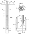
- Figure 1 illustrates an exemplary wellbore 10 which has been drilled from the surface 12 through the earth 14. Although the depicted wellbore 10 is shown as being vertically oriented within the earth 14, it should be understood that the wellbore, or portions thereof, may be inclined or horizontal.
- a coiled tubing injector (not shown) of a type known in the art is located at surface 12 and is used to inject coiled tubing into the wellbore 10.
- a controller 16 is also located at surface 12.
- the controller 16 is preferably a programmable device, such as a computer, which is capable of receiving data in the form of electrical signals from a downhole sensor arrangement for display to a user and/or for storage.
- an electrical power source 18 is located at surface 12 and may be in the form of a generator or battery. The electrical power source 18 should be suitable for transmitting power downhole to a sensor or tool.
- an OTDR optical time-domain reflectometer
- a coiled tubing-based work string 22 is shown being injected into the wellbore 10.
- the work string includes a running string 24 made up of coiled tubing, of a type known in the art, and which defines a central flowbore 26 along its length.
- the work string 22 is useful for conducting one or more of several types of downhole operations within the wellbore 10, as dictated by the variety of bottom hole assembly which is installed on the work string 22.
- a connector 28 and a bottom hole assembly (BHA) 30 are located at the distal end of the running string 24.
- the bottom hole assembly 30 may be a fishing BHA, an acidizing/fracturing BHA, or a cleanout BHA.
- the bottom hole assembly 30 could be any electrically powered tool, such as an electric submersible pump, a tool for opening and closing sliding sleeves or a drilling/milling arrangement.
- the connector 28 connects the bottom hole assembly 30 with the running string 24.
- a hybrid cable 32 extends along the flowbore 26 of the running string 24 to the connector 28. At surface 12, elements of the hybrid cable 32 are operably associated with the controller 16, electrical power source 18 and OTDR 20.
- Figure 2 illustrates an exemplary hybrid cable 32 which permits two-way data communication and two-way power through electrical conductors.
- the cable 32 includes a plurality of electrical conductors or wires 34 which are surrounded by a layer of insulation 36.
- a plurality of optic fibers 38 are located radially outside of the insulation layer 36.
- An outer metallic tubing 40 surrounds the optic fibers 38.
- the electrical conductors or wires 34 are associated at surface 12 with the electrical power source 18 to provide power to one or more sensors, such as sensor 42, or other tools of the bottom hole assembly 30.
- the electrical conductors or wires 34 are also interconnected with the controller 16 and can transmit data from sensor(s) 42 or other tools to the controller 16 so that a first operating parameter or first set of parameters are provided to the controller 16.
- the sensor(s) 42 preferably single point sensors which are capable of detecting wellbore parameters associated with the bottom hole assembly 30 and its proximate location. These parameters can include temperature, pressure, gamma, casing collar location, azimuth, tension, compression and torque.
- the optic fibers 38 are interconnected at surface 12 with the OTDR 20.
- the optic fibers 38 will each typically include a transparent central core with outer cladding which has a lower index of refraction than that of the core.
- One or more of the optic fibers 38 will include a number of Bragg gratings, as known in the art, along their lengths.
- the Bragg gratings are formed within the core of the optic fiber(s) 38 at spaced intervals along the length of the fiber(s) 38.
- the OTDR 20 is used to both generate optical pulses into the optic fiber 38 as well as receive backscattered light from the optical fiber 38.
- the optic fibers 38 provide optical telemetry to the OTDR 20 which is indicative of at least one second operating parameter within the wellbore 10.
- the optic fibers 38 and OTDR 20 are configured to perform distributed temperature sensing (DTS) or distributed acoustic sensing (DAS) and provide telemetry to the OTDR 20.
- DTS distributed temperature sensing
- DAS distributed acoustic sensing
- the optic fibers 38 and OTDR 20 can provide information regarding sensed temperature or acoustics along the length of the optic fiber 38.
- the connector 28 includes a housing 44 having axial ends 46 and 48 which are threaded for attachment of the bottom hole assembly 30 and the running string 24. It is noted that, while threading is depicted, the connector 28 might also be a dimple or roll-on style connector sub.
- the connector 28 defines a flowbore 50 along its length.
- the connector 28 also preferably includes a termination channel 52 for each optic fiber 38. Each optic fiber 38 is terminated within the connector 28 by disposing the distal end of the fiber 38 within a termination channel 52 which contains a gel 54 which is solidified to secure the end within. See Fig. 4 .
- the electrical conductors 34 and insulation layer 36 extend through the connector 28 down to the bottom hole assembly 30.
- the bottom hole assembly 30 includes a bus system and electrical connectors which permit assembly of separate subs within the bottom hole assembly in a modular fashion.
- the bus is preferably a multiconductor line which has a ground, +24VDC and +7.5VDC are well as a two communication lines: signal A and signal B.
- the communication architecture may be based off of the RS-485 standard with a speed of 9600 bits/second. Subs may be interchanged or added to allow construction of a bottom hole assembly 30 having a desired mix of sensors and/or tools.
- Figure 5 illustrates an exemplary bottom hole assembly 30 which is made up of a plurality of interconnected subs 56, 58, 60, 62 and which is useful for conducting a downhole coiled tubing operation.
- the bottom hole assembly 30 is useful for conducting a coiled tubing fishing operation. However, it should be understood that this is by way of example only and that the bottom hole assembly 30 might be used to conduct any and all types of coiled tubing operations.
- a flow through passageway 64 is defined along the length of the bottom hole assembly 30.
- the electrical conductor(s) 34 extend along the length of the passageway 64 of the bottom hole assembly 30.
- Sub 56 includes a fishing tool 66 of a type known in the art for removal of a stuck tool or object within the wellbore 10.
- Sub 58 contains sensors 42 for detection of tool and annulus pressure as well as temperature.
- Sub 60 contains sensors for detection of gamma.
- the electrical conductor(s) 34 is/are preferably provided with detachable connection points 68 which allow the subs 56, 58, 60, 62 to be electrically interconnected in a reversible manner.
- the connection points 68 may comprise USB-type connectors or similar connectors which allow for transmission of power and data.
- the electrical conductor(s) 34 incorporate a modem 70 for transmission of data uphole to the controller 16.
- Individual sensor(s) 42 communicate with the modem 70 which packages the data provided from the sensor(s) 42 and transmits it uphole to the controller 16.
- Each of the subs 56, 58, 60, 62 includes an electronics package, generally indicated at 72 which can include sensors, such as sensor(s) 42, as well as other wellbore electronics, such as those which drive or operate valve actuators or other actuators as well as a processor, logic controller or digitizer and data storage, if desired.
- Electronics packages for various sensor and tool functions may be implemented using printed circuit boards or other methods known in the art.
- Modules in the form of additional sensor and/or tool subs may be added or interchanged with the subs 56, 58, 60, 62, as desired to provide a combination of desired functionality for the bottom hole assembly 30.
- the sub 60 might be replaced by a sub having sensors for detection of tension, compression and torque.
- the bottom hole assembly 30 may be customized to have a desired mix of subs with a corresponding mix of functionality.
- the work string 22 is injected into the wellbore 10 until the bottom hole assembly 30 is located at or near a location 56 within the wellbore 10 wherein it is desired to conduct a downhole operation.
- the downhole operation may include fishing for removal of a stuck tool or object (not shown), fracturing or acidizing, cleanout of a section of the wellbore or other well-known operations.
- the controller 16 receives data representative of a first downhole operating parameter (i.e., temperature, pressure, gamma) from the sensor(s) 42 at the location 56 via the electrical conductor(s) 34. Meanwhile, temperature and/or acoustic data is collected along the length of the flowbore 26 of the work string by the OTDR 20 from the optic fiber(s) 38.
- a first downhole operating parameter i.e., temperature, pressure, gamma
Landscapes
- Engineering & Computer Science (AREA)
- Geology (AREA)
- Life Sciences & Earth Sciences (AREA)
- Mining & Mineral Resources (AREA)
- Physics & Mathematics (AREA)
- General Life Sciences & Earth Sciences (AREA)
- Fluid Mechanics (AREA)
- Environmental & Geological Engineering (AREA)
- Geochemistry & Mineralogy (AREA)
- Geophysics (AREA)
- Remote Sensing (AREA)
- Mechanical Engineering (AREA)
- Health & Medical Sciences (AREA)
- Toxicology (AREA)
- Electromagnetism (AREA)
- Arrangements For Transmission Of Measured Signals (AREA)
- Earth Drilling (AREA)
- Light Guides In General And Applications Therefor (AREA)
Claims (14)
- Train de tiges de travail (22) permettant de mener une opération de fond de trou au sein d'un puits de forage, le train de tiges de travail (22) comprenant :un train de tiges d'exploitation (24) qui définit un orifice d'écoulement (26) ;un ensemble de fond de trou (30) ayant au moins un capteur (42) ou outil alimenté électriquement ;un câble hybride (32) au sein de l'orifice d'écoulement (26), le câble hybride (32) comportant au moins un conducteur électrique (34) et au moins une fibre optique (38) ;un connecteur (28) qui interconnecte l'ensemble de fond de trou (30) au train de tiges d'exploitation (24) ;dans lequel le conducteur électrique (34) traverse le connecteur (28) et est interconnecté avec le capteur (42) ou l'outil alimenté électriquement à l'intérieur de l'ensemble de fond de trou (30) ; etla fibre optique (38) se termine au sein du connecteur (28).
- Train de tiges de travail (22) selon la revendication 1, dans lequel :l'au moins un conducteur électrique (34) transmet l'alimentation d'une source d'alimentation basée en surface (18) au capteur (42) ou à l'outil alimenté électriquement ; etl'au moins un conducteur électrique (34) transmet des données du capteur (42) ou de l'outil alimenté électriquement à un dispositif de commande basé en surface (16) ;dans lequel :l'au moins une fibre optique (38) est interconnectée avec un OTDR (20) au niveau de la surface (12) ; etl'au moins une fibre optique (38) et l'OTDR (20) fonctionnent pour mener une détection de température distribuée ou une détection acoustique distribuée ;dans lequel le conducteur électrique (34) comporte au moins un point de connexion détachable (68) au sein de l'ensemble de fond de trou (30) ;dans lequel :la fibre optique (38) se termine au sein du connecteur (28) en disposant une extrémité distale de la fibre optique (38) au sein d'un canal de terminaison (52) formé au sein du connecteur (28) ;dans lequel :le train de tiges d'exploitation (24) est un train de tiges d'exploitation à tubes spiralés ; etdans lequel :
le câble hybride (32) permet la communication de données bidirectionnelle et l'alimentation bidirectionnelle par l'intermédiaire de conducteurs électriques (34). - Système de télémesure pour un train de tiges de travail de puits de forage (22) ayant un train de tiges d'exploitation (24) et un ensemble de fond de trou (30) fixé au train de tiges d'exploitation (24) par un connecteur (28), le système comprenant :un système de détection optique qui surveille un paramètre de puits de forage le long d'une longueur du train de tiges d'exploitation (24), le système de détection optique comportant une fibre optique (38) qui s'étend le long d'un orifice d'écoulement (26) du train de tiges d'exploitation (24) et qui se termine au sein du connecteur (28) ;un système de télémesure électrique qui comporte au moins un capteur (42) au sein de l'ensemble de fond de trou (30) et un conducteur électrique (34) qui transmet des données du capteur (42) à un dispositif de commande (16).
- Système de télémesure selon la revendication 3, dans lequel :
le système de télémesure électrique comporte au moins un point de connexion détachable (68) au sein de l'ensemble de fond de trou (30). - Système de télémesure selon la revendication 3, dans lequel la fibre optique (38) et le conducteur électrique (34) sont combinés au sein d'un câble hybride (32) qui est disposé au sein du train de tiges d'exploitation (24).
- Système de télémesure selon la revendication 3, dans lequel :
l'au moins un capteur (42) du système de télémesure électrique détecte un ou plusieurs paramètres de puits de forage parmi le groupe constitué par la température, la pression, les rayons gamma, l'emplacement du collier de tubage, l'azimut, la tension, la compression et le couple. - Système de télémesure selon la revendication 3, dans lequel :
le système de détection optique détecte la température distribuée ou les données acoustiques distribuées le long de l'orifice d'écoulement (26). - Système de télémesure selon la revendication 5, dans lequel :
le câble hybride (32) permet la communication de données bidirectionnelle et l'alimentation bidirectionnelle par l'intermédiaire de conducteurs électriques (34). - Système de télémesure selon la revendication 3, dans lequel le conducteur électrique (34) permet une communication de données bidirectionnelle entre le dispositif de commande (16) et l'ensemble de fond de trou (30).
- Système de télémesure selon la revendication 9, dans lequel :
le système de détection optique détecte la température distribuée ou les données acoustiques distribuées le long de l'orifice d'écoulement (26). - Système de télémesure selon la revendication 9, dans lequel :
le système de télémesure électrique comporte au moins un point de connexion détachable (68) au sein de l'ensemble de fond de trou (30). - Système de télémesure selon la revendication 9, dans lequel :
la fibre optique (38) et le conducteur électrique (34) sont combinés au sein d'un câble hybride (32) qui est disposé au sein du train de tiges d'exploitation (24). - Système de télémesure selon la revendication 12, dans lequel :le conducteur électrique (34) est retenu au sein d'une couche d'isolation (36) ; etla fibre optique (38) se trouve radialement à l'extérieur de la couche d'isolation (36).
- Système de télémesure selon la revendication 13, dans lequel :
un tube métallique extérieur (40) entoure radialement le conducteur électrique (34), la couche d'isolation (36) et la fibre optique (38).
Applications Claiming Priority (2)
| Application Number | Priority Date | Filing Date | Title |
|---|---|---|---|
| US17/004,408 US11319803B2 (en) | 2019-04-23 | 2020-08-27 | Coiled tubing enabled dual telemetry system |
| PCT/US2021/047038 WO2022046573A1 (fr) | 2020-08-27 | 2021-08-23 | Système de télémesure double activé par tube spiralé |
Publications (3)
| Publication Number | Publication Date |
|---|---|
| EP4204665A1 EP4204665A1 (fr) | 2023-07-05 |
| EP4204665A4 EP4204665A4 (fr) | 2024-08-21 |
| EP4204665B1 true EP4204665B1 (fr) | 2025-05-21 |
Family
ID=80355608
Family Applications (1)
| Application Number | Title | Priority Date | Filing Date |
|---|---|---|---|
| EP21862444.3A Active EP4204665B1 (fr) | 2020-08-27 | 2021-08-23 | Système de télémesure double activé par tube spiralé |
Country Status (3)
| Country | Link |
|---|---|
| EP (1) | EP4204665B1 (fr) |
| CN (1) | CN116096980A (fr) |
| WO (1) | WO2022046573A1 (fr) |
Family Cites Families (9)
| Publication number | Priority date | Publication date | Assignee | Title |
|---|---|---|---|---|
| US6116085A (en) * | 1998-06-09 | 2000-09-12 | Aec East | Instrumentation tubing string assembly for use in wellbores |
| US8789585B2 (en) * | 2010-10-07 | 2014-07-29 | Schlumberger Technology Corporation | Cable monitoring in coiled tubing |
| CA2870984C (fr) * | 2012-04-27 | 2017-02-21 | Kobold Services Inc. | Procedes et appareils a commande electrique pour des operations de forage de puits |
| EP3234306A4 (fr) * | 2014-12-15 | 2018-08-22 | Baker Hughes Incorporated | Systèmes et procédés pour faire fonctionner des outils de tubes spiralés à actionnement électrique et des capteurs |
| US10502050B2 (en) * | 2015-10-01 | 2019-12-10 | Schlumberger Technology Corporation | Optical rotary joint in coiled tubing applications |
| US10927666B2 (en) * | 2015-12-15 | 2021-02-23 | Halliburton Energy Services, Inc. | Systems and methods for surface detection of electromagnetic signals from subsurface environments |
| MX2019005303A (es) | 2016-11-08 | 2019-08-12 | Baker Hughes A Ge Co Llc | Sistema de tuberia flexible telemetrica dual. |
| US10815774B2 (en) * | 2018-01-02 | 2020-10-27 | Baker Hughes, A Ge Company, Llc | Coiled tubing telemetry system and method for production logging and profiling |
| US11319803B2 (en) * | 2019-04-23 | 2022-05-03 | Baker Hughes Holdings Llc | Coiled tubing enabled dual telemetry system |
-
2021
- 2021-08-23 CN CN202180056688.3A patent/CN116096980A/zh active Pending
- 2021-08-23 EP EP21862444.3A patent/EP4204665B1/fr active Active
- 2021-08-23 WO PCT/US2021/047038 patent/WO2022046573A1/fr not_active Ceased
Also Published As
| Publication number | Publication date |
|---|---|
| EP4204665A4 (fr) | 2024-08-21 |
| EP4204665A1 (fr) | 2023-07-05 |
| BR112023002901A2 (pt) | 2023-03-14 |
| WO2022046573A1 (fr) | 2022-03-03 |
| CN116096980A (zh) | 2023-05-09 |
Similar Documents
| Publication | Publication Date | Title |
|---|---|---|
| EP3538742B1 (fr) | Système de colonne de production spiralée télémétrique double | |
| US7208855B1 (en) | Fiber-optic cable as integral part of a submersible motor system | |
| EP2042683B1 (fr) | Appareil et procédé de chargement en cours de production | |
| US9109439B2 (en) | Wellbore telemetry system and method | |
| US8120508B2 (en) | Cable link for a wellbore telemetry system | |
| US5275038A (en) | Downhole reeled tubing inspection system with fiberoptic cable | |
| US6776233B2 (en) | Method and system for drilling a wellbore having cable based telemetry | |
| EP3044403B1 (fr) | Câble lisse de fibre optique électroconducteur destiné à des opérations de tubage spiralé | |
| US11725468B2 (en) | Electrically conductive fiber optic slickline for coiled tubing operations | |
| US20140367121A1 (en) | Dual Use Cable With Fiber Optic Packaging For Use In Wellbore Operations | |
| US11319803B2 (en) | Coiled tubing enabled dual telemetry system | |
| US20120268288A1 (en) | Arcnet use in downhole equipment | |
| WO2010043690A1 (fr) | Procédé d’installation de capteurs dans un trou de forage | |
| CA2593416C (fr) | Systeme et methode de telemetrie hybride pour puits de forage | |
| EP4204665B1 (fr) | Système de télémesure double activé par tube spiralé | |
| CN101408101B (zh) | 井筒遥测系统和方法 | |
| US20070063865A1 (en) | Wellbore telemetry system and method | |
| EP3039240B1 (fr) | Réduction de surface de tubage câblé | |
| BR112023002901B1 (pt) | Coluna de trabalho para conduzir uma operação de fundo de poço dentro de poço petrolífero e sistema de telemetria para uma coluna de trabalho de poço petrolífero | |
| BR122025020963A2 (pt) | Coluna de trabalho para conduzir uma operação de fundo de poço dentro de poço petrolífero e sistema de telemetria para uma coluna de trabalho de poço petrolífero | |
| AU2019356964B2 (en) | Intervention system and method for operating an intervention system | |
| GB2628968A (en) | Drilling communication assembly |
Legal Events
| Date | Code | Title | Description |
|---|---|---|---|
| STAA | Information on the status of an ep patent application or granted ep patent |
Free format text: STATUS: THE INTERNATIONAL PUBLICATION HAS BEEN MADE |
|
| PUAI | Public reference made under article 153(3) epc to a published international application that has entered the european phase |
Free format text: ORIGINAL CODE: 0009012 |
|
| STAA | Information on the status of an ep patent application or granted ep patent |
Free format text: STATUS: REQUEST FOR EXAMINATION WAS MADE |
|
| 17P | Request for examination filed |
Effective date: 20230207 |
|
| AK | Designated contracting states |
Kind code of ref document: A1 Designated state(s): AL AT BE BG CH CY CZ DE DK EE ES FI FR GB GR HR HU IE IS IT LI LT LU LV MC MK MT NL NO PL PT RO RS SE SI SK SM TR |
|
| DAV | Request for validation of the european patent (deleted) | ||
| DAX | Request for extension of the european patent (deleted) | ||
| A4 | Supplementary search report drawn up and despatched |
Effective date: 20240723 |
|
| RIC1 | Information provided on ipc code assigned before grant |
Ipc: E21B 47/135 20120101ALI20240717BHEP Ipc: E21B 47/113 20120101ALI20240717BHEP Ipc: E21B 47/06 20120101ALI20240717BHEP Ipc: E21B 17/20 20060101ALI20240717BHEP Ipc: E21B 17/04 20060101ALI20240717BHEP Ipc: E21B 41/00 20060101ALI20240717BHEP Ipc: E21B 17/00 20060101ALI20240717BHEP Ipc: E21B 47/125 20120101AFI20240717BHEP |
|
| GRAP | Despatch of communication of intention to grant a patent |
Free format text: ORIGINAL CODE: EPIDOSNIGR1 |
|
| STAA | Information on the status of an ep patent application or granted ep patent |
Free format text: STATUS: GRANT OF PATENT IS INTENDED |
|
| RIC1 | Information provided on ipc code assigned before grant |
Ipc: E21B 47/135 20120101ALI20250220BHEP Ipc: E21B 47/113 20120101ALI20250220BHEP Ipc: E21B 47/06 20120101ALI20250220BHEP Ipc: E21B 17/20 20060101ALI20250220BHEP Ipc: E21B 17/04 20060101ALI20250220BHEP Ipc: E21B 41/00 20060101ALI20250220BHEP Ipc: E21B 17/00 20060101ALI20250220BHEP Ipc: E21B 47/125 20120101AFI20250220BHEP |
|
| INTG | Intention to grant announced |
Effective date: 20250305 |
|
| GRAS | Grant fee paid |
Free format text: ORIGINAL CODE: EPIDOSNIGR3 |
|
| GRAA | (expected) grant |
Free format text: ORIGINAL CODE: 0009210 |
|
| STAA | Information on the status of an ep patent application or granted ep patent |
Free format text: STATUS: THE PATENT HAS BEEN GRANTED |
|
| AK | Designated contracting states |
Kind code of ref document: B1 Designated state(s): AL AT BE BG CH CY CZ DE DK EE ES FI FR GB GR HR HU IE IS IT LI LT LU LV MC MK MT NL NO PL PT RO RS SE SI SK SM TR |
|
| REG | Reference to a national code |
Ref country code: GB Ref legal event code: FG4D |
|
| REG | Reference to a national code |
Ref country code: CH Ref legal event code: EP |
|
| REG | Reference to a national code |
Ref country code: DE Ref legal event code: R096 Ref document number: 602021031259 Country of ref document: DE |
|
| REG | Reference to a national code |
Ref country code: IE Ref legal event code: FG4D |
|
| REG | Reference to a national code |
Ref country code: NL Ref legal event code: MP Effective date: 20250521 |
|
| P01 | Opt-out of the competence of the unified patent court (upc) registered |
Free format text: CASE NUMBER: UPC_APP_4411_4204665/2025 Effective date: 20250825 |
|
| PG25 | Lapsed in a contracting state [announced via postgrant information from national office to epo] |
Ref country code: PT Free format text: LAPSE BECAUSE OF FAILURE TO SUBMIT A TRANSLATION OF THE DESCRIPTION OR TO PAY THE FEE WITHIN THE PRESCRIBED TIME-LIMIT Effective date: 20250922 Ref country code: FI Free format text: LAPSE BECAUSE OF FAILURE TO SUBMIT A TRANSLATION OF THE DESCRIPTION OR TO PAY THE FEE WITHIN THE PRESCRIBED TIME-LIMIT Effective date: 20250521 Ref country code: ES Free format text: LAPSE BECAUSE OF FAILURE TO SUBMIT A TRANSLATION OF THE DESCRIPTION OR TO PAY THE FEE WITHIN THE PRESCRIBED TIME-LIMIT Effective date: 20250521 |
|
| REG | Reference to a national code |
Ref country code: LT Ref legal event code: MG9D |
|
| PG25 | Lapsed in a contracting state [announced via postgrant information from national office to epo] |
Ref country code: GR Free format text: LAPSE BECAUSE OF FAILURE TO SUBMIT A TRANSLATION OF THE DESCRIPTION OR TO PAY THE FEE WITHIN THE PRESCRIBED TIME-LIMIT Effective date: 20250822 |
|
| PGFP | Annual fee paid to national office [announced via postgrant information from national office to epo] |
Ref country code: NO Payment date: 20250725 Year of fee payment: 5 |
|
| PG25 | Lapsed in a contracting state [announced via postgrant information from national office to epo] |
Ref country code: PL Free format text: LAPSE BECAUSE OF FAILURE TO SUBMIT A TRANSLATION OF THE DESCRIPTION OR TO PAY THE FEE WITHIN THE PRESCRIBED TIME-LIMIT Effective date: 20250521 Ref country code: NL Free format text: LAPSE BECAUSE OF FAILURE TO SUBMIT A TRANSLATION OF THE DESCRIPTION OR TO PAY THE FEE WITHIN THE PRESCRIBED TIME-LIMIT Effective date: 20250521 |
|
| PG25 | Lapsed in a contracting state [announced via postgrant information from national office to epo] |
Ref country code: BG Free format text: LAPSE BECAUSE OF FAILURE TO SUBMIT A TRANSLATION OF THE DESCRIPTION OR TO PAY THE FEE WITHIN THE PRESCRIBED TIME-LIMIT Effective date: 20250521 |
|
| PGFP | Annual fee paid to national office [announced via postgrant information from national office to epo] |
Ref country code: GB Payment date: 20250724 Year of fee payment: 5 |
|
| PG25 | Lapsed in a contracting state [announced via postgrant information from national office to epo] |
Ref country code: HR Free format text: LAPSE BECAUSE OF FAILURE TO SUBMIT A TRANSLATION OF THE DESCRIPTION OR TO PAY THE FEE WITHIN THE PRESCRIBED TIME-LIMIT Effective date: 20250521 |
|
| PG25 | Lapsed in a contracting state [announced via postgrant information from national office to epo] |
Ref country code: RS Free format text: LAPSE BECAUSE OF FAILURE TO SUBMIT A TRANSLATION OF THE DESCRIPTION OR TO PAY THE FEE WITHIN THE PRESCRIBED TIME-LIMIT Effective date: 20250821 |
|
| PG25 | Lapsed in a contracting state [announced via postgrant information from national office to epo] |
Ref country code: IS Free format text: LAPSE BECAUSE OF FAILURE TO SUBMIT A TRANSLATION OF THE DESCRIPTION OR TO PAY THE FEE WITHIN THE PRESCRIBED TIME-LIMIT Effective date: 20250921 |
|
| PG25 | Lapsed in a contracting state [announced via postgrant information from national office to epo] |
Ref country code: LV Free format text: LAPSE BECAUSE OF FAILURE TO SUBMIT A TRANSLATION OF THE DESCRIPTION OR TO PAY THE FEE WITHIN THE PRESCRIBED TIME-LIMIT Effective date: 20250521 |
|
| REG | Reference to a national code |
Ref country code: AT Ref legal event code: MK05 Ref document number: 1796903 Country of ref document: AT Kind code of ref document: T Effective date: 20250521 |
|
| PG25 | Lapsed in a contracting state [announced via postgrant information from national office to epo] |
Ref country code: AT Free format text: LAPSE BECAUSE OF FAILURE TO SUBMIT A TRANSLATION OF THE DESCRIPTION OR TO PAY THE FEE WITHIN THE PRESCRIBED TIME-LIMIT Effective date: 20250521 Ref country code: SM Free format text: LAPSE BECAUSE OF FAILURE TO SUBMIT A TRANSLATION OF THE DESCRIPTION OR TO PAY THE FEE WITHIN THE PRESCRIBED TIME-LIMIT Effective date: 20250521 Ref country code: DK Free format text: LAPSE BECAUSE OF FAILURE TO SUBMIT A TRANSLATION OF THE DESCRIPTION OR TO PAY THE FEE WITHIN THE PRESCRIBED TIME-LIMIT Effective date: 20250521 |
|
| PG25 | Lapsed in a contracting state [announced via postgrant information from national office to epo] |
Ref country code: CZ Free format text: LAPSE BECAUSE OF FAILURE TO SUBMIT A TRANSLATION OF THE DESCRIPTION OR TO PAY THE FEE WITHIN THE PRESCRIBED TIME-LIMIT Effective date: 20250521 |
|
| PG25 | Lapsed in a contracting state [announced via postgrant information from national office to epo] |
Ref country code: EE Free format text: LAPSE BECAUSE OF FAILURE TO SUBMIT A TRANSLATION OF THE DESCRIPTION OR TO PAY THE FEE WITHIN THE PRESCRIBED TIME-LIMIT Effective date: 20250521 |
|
| PG25 | Lapsed in a contracting state [announced via postgrant information from national office to epo] |
Ref country code: SK Free format text: LAPSE BECAUSE OF FAILURE TO SUBMIT A TRANSLATION OF THE DESCRIPTION OR TO PAY THE FEE WITHIN THE PRESCRIBED TIME-LIMIT Effective date: 20250521 |
|
| PG25 | Lapsed in a contracting state [announced via postgrant information from national office to epo] |
Ref country code: IT Free format text: LAPSE BECAUSE OF FAILURE TO SUBMIT A TRANSLATION OF THE DESCRIPTION OR TO PAY THE FEE WITHIN THE PRESCRIBED TIME-LIMIT Effective date: 20250521 |
|
| REG | Reference to a national code |
Ref country code: DE Ref legal event code: R097 Ref document number: 602021031259 Country of ref document: DE |
|
| REG | Reference to a national code |
Ref country code: DE Ref legal event code: R119 Ref document number: 602021031259 Country of ref document: DE |
|
| PG25 | Lapsed in a contracting state [announced via postgrant information from national office to epo] |
Ref country code: RO Free format text: LAPSE BECAUSE OF FAILURE TO SUBMIT A TRANSLATION OF THE DESCRIPTION OR TO PAY THE FEE WITHIN THE PRESCRIBED TIME-LIMIT Effective date: 20250521 |
|
| REG | Reference to a national code |
Ref country code: CH Ref legal event code: H13 Free format text: ST27 STATUS EVENT CODE: U-0-0-H10-H13 (AS PROVIDED BY THE NATIONAL OFFICE) Effective date: 20260324 |
|
| PLBE | No opposition filed within time limit |
Free format text: ORIGINAL CODE: 0009261 |
|
| STAA | Information on the status of an ep patent application or granted ep patent |
Free format text: STATUS: NO OPPOSITION FILED WITHIN TIME LIMIT |
|
| PG25 | Lapsed in a contracting state [announced via postgrant information from national office to epo] |
Ref country code: MC Free format text: LAPSE BECAUSE OF FAILURE TO SUBMIT A TRANSLATION OF THE DESCRIPTION OR TO PAY THE FEE WITHIN THE PRESCRIBED TIME-LIMIT Effective date: 20250521 |
|
| REG | Reference to a national code |
Ref country code: CH Ref legal event code: L10 Free format text: ST27 STATUS EVENT CODE: U-0-0-L10-L00 (AS PROVIDED BY THE NATIONAL OFFICE) Effective date: 20260402 |
|
| PG25 | Lapsed in a contracting state [announced via postgrant information from national office to epo] |
Ref country code: LU Free format text: LAPSE BECAUSE OF NON-PAYMENT OF DUE FEES Effective date: 20250823 |
|
| PG25 | Lapsed in a contracting state [announced via postgrant information from national office to epo] |
Ref country code: CH Free format text: LAPSE BECAUSE OF NON-PAYMENT OF DUE FEES Effective date: 20250831 |
|
| 26N | No opposition filed |
Effective date: 20260224 |