EP4205145B1 - Behälterverschluss mit wirbelerzeugungsfunktion - Google Patents
Behälterverschluss mit wirbelerzeugungsfunktion Download PDFInfo
- Publication number
- EP4205145B1 EP4205145B1 EP21773230.4A EP21773230A EP4205145B1 EP 4205145 B1 EP4205145 B1 EP 4205145B1 EP 21773230 A EP21773230 A EP 21773230A EP 4205145 B1 EP4205145 B1 EP 4205145B1
- Authority
- EP
- European Patent Office
- Prior art keywords
- container
- closure
- flow path
- inlet flow
- outlet
- Prior art date
- Legal status (The legal status is an assumption and is not a legal conclusion. Google has not performed a legal analysis and makes no representation as to the accuracy of the status listed.)
- Active
Links
Images


Classifications
-
- G—PHYSICS
- G21—NUCLEAR PHYSICS; NUCLEAR ENGINEERING
- G21F—PROTECTION AGAINST X-RADIATION, GAMMA RADIATION, CORPUSCULAR RADIATION OR PARTICLE BOMBARDMENT; TREATING RADIOACTIVELY CONTAMINATED MATERIAL; DECONTAMINATION ARRANGEMENTS THEREFOR
- G21F5/00—Transportable or portable shielded containers
- G21F5/015—Transportable or portable shielded containers for storing radioactive sources, e.g. source carriers for irradiation units; Radioisotope containers
-
- B—PERFORMING OPERATIONS; TRANSPORTING
- B01—PHYSICAL OR CHEMICAL PROCESSES OR APPARATUS IN GENERAL
- B01D—SEPARATION
- B01D1/00—Evaporating
- B01D1/14—Evaporating with heated gases or vapours or liquids in contact with the liquid
-
- G—PHYSICS
- G21—NUCLEAR PHYSICS; NUCLEAR ENGINEERING
- G21G—CONVERSION OF CHEMICAL ELEMENTS; RADIOACTIVE SOURCES
- G21G1/00—Arrangements for converting chemical elements by electromagnetic radiation, corpuscular radiation or particle bombardment, e.g. producing radioactive isotopes
- G21G1/0005—Isotope delivery systems
Definitions
- the field of the disclosure relates generally to production of radionuclides and, more particularly, to a container closure for use in systems and methods for preparing radionuclide solutions.
- Radiopharmaceuticals drugs that incorporate a radioactive element (i.e., a radionuclide), are used in nuclear medicine for diagnostic and/or therapeutic purposes.
- Radionuclides typically used in nuclear medicine include technetium-99m (Tc-99m), indium-111 (In-111), thallium-201 (TI-201), fluorine-18 (F-18), and copper-64 ("Cu-64"), among others.
- Radionuclides may be produced naturally, or via decay of a long-lived parent (i.e., a radionuclide generator), or by direct production (e.g., proton- or neutron-induced reaction).
- radionuclides and radiopharmaceuticals it is desirable to concentrate a radionuclide precursor solution to dryness or near-dryness.
- solvent evaporation is often used as the penultimate step before final reconstitution of the precursor in a biocompatible solvent, either for direct injection or incorporation into a biomolecule (e.g., monoclonal antibody).
- purification of a radiopharmaceutical agent using a reversed-phase C18 column may require subsequent removal of a bioincompatible organic solvent (e.g., acetonitrile). Accordingly, a need exists for processes and apparatuses that facilitate concentrating liquid radionuclide precursor solutions to dryness or near-dryness.
- a closure in one aspect, includes a body extending longitudinally along a central longitudinal axis from a first, upper surface to a second, lower surface.
- the body defines a cavity extending into the body from the lower surface to a third, interior surface.
- the cavity is sized and shaped to receive a portion of a container therein.
- the body includes a shroud extending from the interior surface to the lower surface, and a container insert depending from the interior surface and positioned within the cavity.
- the container insert is sized and shaped to fit within an opening of the container.
- the body further includes an outlet flow path in fluid communication with the cavity, and at least one inlet flow path in fluid communication with the cavity.
- the at least one inlet flow path is positioned and oriented to generate a vortex gas flow within the container when connected thereto.
- Each of the at least one inlet flow path is oriented at an oblique angle relative to the central longitudinal axis of the body, and radially offset from the central longitudinal axis.
- a system in another aspect, includes a radiation containment chamber, a remote manipulator connected to the radiation containment chamber, a container positioned within an interior of the radiation containment chamber, a closure, as defined in claim 1, connected to the container and including a body including an outlet flow path and at least one inlet flow path, an evaporation station positioned within the interior of the radiation containment chamber and including at least one heating element for applying heat to the container, and a gas handling system including a suction line connected to an outlet of the outlet flow path.
- the at least one inlet flow path of the closure generates a vortex gas flow within the container when suction is applied to the container by the suction line.
- a closure as defined in claim 1
- the closure includes at least one inlet flow path and an outlet flow path.
- the method further includes directing a flow of gas through the at least one inlet flow path of the closure to generate a vortex gas flow within the container.
- FIG. 1 is a schematic view of a system 100 for preparing radionuclide solutions.
- the system 100 shown in FIG. 1 may be used to prepare or otherwise process various radioactive solutions, including, for example and without limitation, solutions containing non-volatile species or complexes of F-18, Sc-43, Sc-44, Sc-47, Ti-44, Ti-45, Co-55, Cu-64, Cu-67, Ge-68, Ga-68, Rb-82, Sr-82, Sr-89, Sr-87m, Zr-89, Y-86, Y-90, Mo-99, Tc-99m, In-111, 1-123, 1-125, 1-131, Sm-153, Lu-177, Re-186, Re-188, Au-198, TI-201, Pb-203, At-211, Ra-223, and Ac-225.
- the system 100 generally includes a nuclear radiation containment chamber 102, also referred to herein as a "hot cell", an evaporation station 104 enclosed within the radiation containment chamber 102, a gas handling system 106, a remote manipulator 108, and a container assembly 110 having a radioactive liquid 112 contained therein.
- radioactive liquids 112 that can be used in the system 100 include liquids used in the preparation of radionuclides (e.g., a radioactive solution or radionuclide precursor solution), or other radioactive liquids, such as radiolabeled compounds (e.g., radiopharmaceutical agents or complexed radioactive precursors).
- the evaporation station 104 and container assembly 110 are enclosed within the containment chamber 102 to shield operators from nuclear radiation emitted by radioactive materials within the containment chamber 102 (e.g., radioactive liquid 112).
- the containment chamber 102 generally includes an enclosure 114 constructed of nuclear radiation shielding material designed to shield the surrounding environment from nuclear radiation.
- the enclosure 114 defines an interior 116 in which the evaporation station 104 is positioned.
- Suitable shielding materials from which the containment chamber 102 may be constructed include, for example and without limitation, lead, depleted uranium, and tungsten.
- the containment chamber 102 is constructed of steel-clad lead walls forming a cuboid or rectangular prism.
- the containment chamber 102 may include a viewing window constructed of a transparent shielding material. Suitable materials from which viewing windows may be constructed include, for example and without limitation, lead glass.
- the evaporation station 104 includes one or more devices to evaporate the radioactive liquid 112. Suitable devices for use in the evaporation station 104 include, for example and without limitation, heating elements, such as hot plates, resistive heaters, fluid-based heaters or heat exchanges, and gas-fired heaters.
- the evaporation station 104 includes a hot plate 118 having a selectively-adjustable temperature that allows an operator to set a desired temperature to which the container assembly 110 and radioactive liquid 112 are heated during an evaporation process.
- the gas handling system 106 is operable to supply and remove gas from the containment chamber 102, such as from within the evaporation station 104.
- the gas handling system 106 is configured to remove gases and volatile compounds generated during an evaporation process at the evaporation station 104.
- the gas handling system 106 can include any suitable components that enables the gas handling system 106 to function as described herein, including, for example and without limitation, fluid conduits, pumps, pressurized-gas supplies, filters, traps, and combinations thereof.
- the gas handling system 106 includes a pump 120, a suction line 122 connected to an inlet 124 of the pump 120, and one or more gas supply lines 126.
- the pump 120 and associated electronics and controls are positioned outside of the radiation containment chamber 102 to shield the components from radiation.
- the pump 120 can generally include any suitable pump that enables the gas handling system 106 to function as described herein, including, for example and without limitation, a reciprocating pump, a rotary pump, a centrifugal pump, a positive displacement pump, and combinations thereof.
- the suction line 122 is connected to the inlet 124 of the pump 120, and includes an inlet end 128 that connects to the container assembly 110 to provide suction thereto.
- Each gas supply line 126 is connected to a pressurized gas source 130 (e.g., compressor, pressurized inert gas supply tanks, etc.), and includes an outlet end 132 that connects to the container assembly 110 to provide a flow of gas thereto.
- the suction line 122 and gas supply lines 126 can generally include any suitable fluid conduit that enables the gas handling the system 100 to function as described herein, including, for example and without limitation, tubes, hoses, pipes, and combinations thereof. Additionally, the suction line 122 and gas supply lines 126 can include rigid conduits, flexible conduits, and combinations thereof.
- the inlet end 128 of the suction line 122 and the outlet end 132 of each of the gas supply lines 126 can include suitable fluid couplers and/or adapters to facilitate connection to the container assembly 110.
- suitable fluid couplers and adapters include, for example and without limitation, Luer fittings, threaded couplers, compression fittings, and combinations thereof.
- the illustrated gas handling system 106 also includes a trap 134 connected to the suction line 122 upstream of the pump inlet 124.
- the trap 134 collects volatile species (e.g., HCl gas) and/or water vapor (e.g., using a desiccant) evaporated from the radioactive liquid 112 during the evaporation process, as well as small particulates entrained in the gas flow through the suction line 122.
- volatile species e.g., HCl gas
- water vapor e.g., using a desiccant
- the remote manipulator 108 is connected to the radiation containment chamber 102, and allows manipulation of objects (e.g., the container assembly 110) within the containment chamber 102 from a remote location, such as outside the containment chamber 102.
- objects e.g., the container assembly 110
- a remote location such as outside the containment chamber 102.
- Examples of remote manipulators suitable for use with the system 100 include telemanipulators, autonomous or semi-autonomous systems (e.g., robotic arms), and manual instruments that extend an operator's reach (e.g., long forceps).
- the remote manipulator 108 is illustrated in the form of a telemanipulator that allows an operator outside of the containment chamber 102 to manipulate objects (e.g., the container assembly 110) within the containment chamber 102.
- the telemanipulator can have any suitable telemanipulator configuration that enables the system 100 to function as described herein.
- the telemanipulator includes an operator handle or controller 136 positioned outside of the radiation containment chamber 102, an articulated arm 138 connected to the controller 136 and positioned within the containment chamber 102, and an end effector 140 positioned at a distal end of the articulated arm 138.
- the operator controller 136 can be used, for example, to control a position, orientation, and/or state (e.g., opened or closed) of the end effector 140.
- the end effector 140 includes mechanical fingers or clamps that allow an operator to grip or clamp objects (e.g., the container assembly 110) within the radiation containment chamber 102.
- the system 100 may include more than one telemanipulator.
- the system 100 includes two telemanipulators such that an operator can control one telemanipulator with their left hand, and another telemanipulator with their right hand.
- the system 100 may include a combination of remote manipulators 108 (e.g., a telemanipulator and an autonomous robotic arm).
- the container assembly 110 includes a container 142 and a cap or closure 144 connected to the container 142.
- the container 142 is generally configured to hold a volume of liquid therein.
- the container 142 may be sized to hold any suitable volume of the radioactive liquid 112 therein.
- the container 142 is sized to hold a relatively small volume of the radioactive liquid 112 therein, such as less than 100 mL, less than 80 mL, less than 60 mL, less than 40 mL, less than 30 mL, less than 20 mL, or even less than 10 mL.
- the container 142 may be sized to hold a volume of the radioactive liquid 112 greater than 100 mL.
- the container 142 is constructed of a chemically inert material, including, for example and without limitation, glass (borosilicate glass, Pyrex ® ), quartz, polyoxymethylene (e.g., Delrin ® ), polycarbonate, polytetrafluoroethylene (e.g., Teflon TM ), polypropylene, and other plastics compatible with the solvent being evaporated.
- glass borosilicate glass, Pyrex ®
- quartz borosilicate glass
- polyoxymethylene e.g., Delrin ®
- polycarbonate e.g., polytetrafluoroethylene (e.g., Teflon TM )
- Teflon TM polytetrafluoroethylene
- polypropylene polypropylene
- the closure 144 is configured to seal against a portion of the container 142 when connected thereto to control the flow of gas within the container 142 during an evaporation process.
- the closure 144 is connected directly to the container 142.
- the closure 144 can be connected to or otherwise include an adapter or peripheral component to facilitate connection to containers of varying shapes and sizes (e.g., containers with different sized and/or shaped openings).
- the closure 144 is connectable to a plurality of different adapters, each sized and shaped to fit a different container such that the closure 144 is connectable to and usable with a plurality of different containers (e.g., vials, centrifuge tubes, round bottom flasks, etc.).
- the closure 144 of the illustrated embodiment is designed to facilitate evaporation of the radioactive liquid 112 within the container 142.
- the closure 144 includes at least one vortex-generating feature that generates a vortex and associated centrifugal forces within the container 142 during the evaporation process, increasing the surface area of the liquid 112 and thereby accelerating the evaporation process.
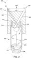
- FIG. 2 is a cross-sectional view of an example container assembly 200, including a container 202 and a closure 204, suitable for use with the system 100 of FIG. 1 .
- the container 202 of the illustrated embodiment generally includes a bottom 206, a sidewall 208 extending upward from the bottom 206, and a neck 210 defining an opening 212 at a top of the container 202.
- the sidewall 208 extends from the bottom 206 to the neck 210, and joins the neck 210 at a rounded shoulder portion 214 where the container 202 transitions from a larger diameter along the sidewall 208 to a smaller diameter along the neck 210.
- the sidewall 208 and the neck 210 may have the same diameter, and the container 202 may not have a shoulder portion 214.
- the container 202 having a volume of the radioactive liquid 112 (shown in broken lines in FIG. 2 ) contained therein is positioned within the containment chamber 102.
- the closure 204 is connected to the container 202, using the remote manipulator 108, to cover or occlude the container opening 212, and the suction line 122 and/or gas supply lines 126 are connected to the closure 204.
- the container 202 is positioned at the evaporation station 104 (e.g., on and/or adjacent to the hot plate 118), and heat is applied to the container 202 while gas is fed to and/or evacuated from the container 202 via the gas handling system 106.
- the closure 204 seals against a portion of the container (e.g., the sidewall 208 and/or the neck 210), thereby providing a closed system to inhibit or prevent the introduction of environmental contaminants (e.g., trace metallic contaminants) into the container 202. Additionally, the closure 204 provides a dedicated path for collection of gases and other volatile species evaporated during the evaporation processes via the gas handling system 106. Compounds evaporated from the radioactive liquid 112 can be highly corrosive (e.g., HCl gas and water) and cause corrosion of components within the containment chamber 102, and/can accumulate and be released in unwanted areas if not properly collected and disposed of.
- HCl gas and water highly corrosive
- the closure 204 also facilitates the evaporation process by increasing the rate of evaporation.
- embodiments of the closures described herein are configured to introduce gas flow into the container 202 in such a way that the liquid 112 is stirred in a vortex motion, thereby increasing the surface area of the liquid 112 and accelerating the evaporation rate.
- the closure 204 may have any suitable construction that enables the system 100 and container assembly 200 to function as described herein.
- the closure 204 generally includes a body 302 having an exterior surface 304, and at least one inlet flow path 306 and an outlet flow path 308 defined therein.
- the inlet flow path or paths 306 are vortex-generating features. More specifically, the inlet flow paths 306 are configured (e.g., positioned and oriented) to generate a vortex gas flow (illustrated by arrows 216 in FIG. 2 ) within the container 202 when connected thereto and gas is directed through the inlet flow paths 306 (e.g., via the gas handling system 106).
- the inlet flow paths 306 also help prevent bubbling of liquid contained within the container 202, for example, by preventing or limiting the container 202 being placed under high vacuum.
- the outlet flow path 308 provides an exit or exhaust flow path for gases and volatile compounds generated during an evaporation process.
- Each of the inlet flow paths 306 includes an inlet 310 defined on the body exterior surface 304, and an outlet 312.
- the outlet flow path 308 includes an outlet 314 defined on the body exterior surface 304, and an inlet 316.
- the inlet flow path outlets 312 and the outlet flow path inlet 316 are positioned on the closure 204 such that, when the closure 204 is connected to the container 202, the inlet flow path outlets 312 and the outlet flow path inlet 316 are in fluid communication with the container interior.
- the body 302 extends longitudinally along a central longitudinal axis 318 from a first, upper surface 320 to a second, lower surface 322.
- the body 302 includes four side surfaces 324 extending from the upper surface 320 to the lower surface 322.
- Each of the side surfaces 324 has a rectangular shape and is generally flat or planar.
- the upper surface 320, lower surface 322, and four side surfaces 324 define the body exterior surface 304.
- the body 302 defines a cavity 326 that extends into the body 302 from the lower surface 322 to a third, interior surface 328.
- the cavity 326 is sized and shaped to receive a portion of the container 202 therein, such as the neck 210, shoulder portion 214, and/or sidewall 208.
- the cavity 326 is shaped cylindrically, although in other embodiments the cavity 326 may be shaped differently, such as square, rectangular, polygonal, ellipsoidal, or any other shape that enables the closure 204 to function as described herein.
- the body 302 includes a shroud 330 that extends from the interior surface 328 to the lower surface 322.
- the shroud 330 includes a radial inner surface 332 that at least partially defines the cavity 326.
- the body 302 also includes a container insert 334 that depends from the interior surface 328 and is positioned within the cavity 326.
- the container insert 334 is sized and shaped to fit within the container opening 212 when the closure 204 is connected to the container 202.
- the shroud 330 of the illustrated embodiment extends axially beyond the container insert 334 and can therefore function as a guide for the closure 204 as the closure 204 is connected to the container 202.
- the container insert 334 includes an outlet extension 336 depending from a lower surface 338 of the container insert 334.
- the outlet extension 336 defines the outlet flow path inlet 316.
- the inlet flow path outlets 312 are defined adjacent the lower surface 338 of the container insert 334.
- the outlet flow path inlet 316 is axially offset from each of the inlet flow path outlets 312 to reduce or minimize interference between incoming gas flow and exiting gas flow.
- the outlet flow path inlet 316 is positioned lower than (i.e., closer to the second, lower surface 322 of the body 302) than the inlet flow path outlets 312.
- the inlet flow path outlets 312 may be positioned lower than (i.e., closer to the second, lower surface 322) than the outlet flow path inlet 316.
- the container insert 334 and outlet extension 336 are shaped cylindrically, where the outlet extension 336 has a smaller diameter than the remainder of the container insert 334. In other embodiments, the container insert 334 may be shaped other than cylindrical.
- the example closure 204 includes two inlet flow paths 306, and a single outlet flow path 308.
- the closure 204 may have fewer than two inlet flow paths 306 (e.g., one inlet flow path), or greater than two inlet flow paths 306 (e.g., three inlet flow paths, four inlet flow paths, etc.). Additionally, the closure 204 may have more than one outlet flow path 308 in other embodiments.
- each of the inlet flow paths 306 extends from the body exterior surface 304, through the body 302, into communication with the cavity 326.
- the inlet flow path inlets 310 are defined on the upper surface 320
- the inlet flow path outlets 312 are defined along the lower surface 338 of the container insert 334.
- the inlet flow path inlets 310 and outlets 312 may be defined along any other suitable portion of the body 302 that enables the closure 204 to function as described herein.
- the inlet flow paths 306 are configured as vortex generating features to facilitate evaporation of a liquid within the container 202. More specifically, the inlet flow paths 306 are oriented at suitable angles and positioned at suitable locations on the closure 204 such that gas flow directed through the inlet flow paths 306 creates a vortex air or gas flow within the container 202. In the illustrated embodiment, each inlet flow path 306 is oriented at an oblique angle 340 ( FIG. 5 ) relative to the central longitudinal axis 318, and is radially offset from the central longitudinal axis 318.
- Each inlet flow path 306 is oriented at an angle 340 of about 30° relative to the central longitudinal axis 318 in the illustrated embodiment, although the inlet flow paths 306 may be oriented at an angle other than 30° in other embodiments.
- each inlet flow path 306 may be oriented relative to the central longitudinal axis 318 at an angle of between between 5° and 75°, between 5° and 60°, between 15° and 70°, between 5° and 45°, between 15° and 55 °, between 25° and 65°, between 5° and 35°, between 15° and 45°, between 25° and 55°, between 35° and 65°, between 10° and 30°, between 20° and 40°, between 30° and 50°, or between 40° and 60°.
- each inlet flow path 306 extends linearly from the inlet flow path inlet 310 to the inlet flow path outlet 312. In other embodiments, one or more of the inlet flow paths 306 may extend non-linearly, such as in a curvilinear or spiral configuration.
- the inlet flow paths 306 are also spaced uniformly about the central longitudinal axis 318 in a circumferential direction to provide balanced gas flow into the container 202. For example, as shown in FIGS. 3 and 6 , the inlet flow path inlets 310 and outlets 312 are spaced evenly about the central longitudinal axis 318 in the circumferential direction.
- the illustrated embodiment includes two inlet flow paths 306, so the inlet flow paths 306 and their associated inlets 310 and outlets 312 are positioned diametrically opposite one another.
- the outlet flow path 308 is parallel to and coaxial with the central longitudinal axis 318 in the example embodiment. In other embodiments, the outlet flow path 308 may be other than parallel to and/or coaxial with the central longitudinal axis 318.
- a vortex is generated within the container 202, as illustrated by arrows 216 in FIG. 2 .
- the vortex creates centrifugal forces inside the container 202, which increases the surface area of the radioactive liquid and thereby accelerates the evaporation process.
- Gas flow may be directed through the inlet flow paths 306 and outlet flow path 308 using the gas handling system 106 (shown in FIG. 1 ).
- the suction line 122 is connected to the outlet flow path outlet 316, and the gas supply lines 126 are connected to the inlet flow path inlets 310.
- only the suction line 122 is connected to the closure 204, and ambient gas (e.g., within the containment chamber 102) flows through the inlet flow paths 306 as a result of a negative pressure differential generated within the container 202 by the suction line 122.
- the gas supply lines 126 may be omitted.
- the inlet flow path inlets 310 and the outlet flow path outlet 316 may include suitable adapters, couplers, or be otherwise configured for coupling to the gas supply lines 126 and suction line 122, respectively.
- one or more of the inlet flow path inlets 310 and the outlet flow path outlet 316 can be threaded (e.g., with a 10-32 or 10-24 type thread) to facilitate threadably coupling an adapter to the respective inlet or outlet.
- the inlet flow path 306 may include one or more filters positioned therein to filter incoming gas flow. The filters can be connected to the inlet flow path inlets 310 with suitable adapters or couplers, such as a Luer adapter.
- the closure 204 seals against a portion the container 202 such that gas flow into and out of the container is permitted only through the inlet flow paths 306 and the outlet flow path 308.
- the closure 204 may include one or more seals or sealing materials to facilitate forming a seal against the container 202.
- the closure 204 may include one or more elastomeric seals (e.g., O-rings) that engage a portion of the container 202 to form a seal therewith when the closure 204 is inserted over the top of the container 202.
- the elastomeric seals may be positioned and held in place within grooves defined in the closure body 302.
- the body 302 has a groove defined along the radial inner surface 332 of the shroud 330, and an elastomeric seal is positioned within the groove such that the seal engages the shoulder portion 214 and/or sidewall 208 of the container 202 to form a seal against the container 202.
- the interior surface 328 and/or a radial outer surface of the container insert 334 may include a groove and an elastomeric seal positioned therein to facilitate forming a seal between the closure 204 and the container 202.
- the closure 204 of the illustrated embodiment is particularly suited for use in a radioactive environment (e.g., in the production of radionuclides and radionuclide precursors).
- the closure 204 is constructed of materials resistant to both radiation degradation and corrosive gases evaporated during an evaporation process (e.g., HCl gas and water).
- Suitable materials include, for example and without limitation, polytetrafluoroethylene (e.g., Teflon TM ), perfluoroalkoxy alkanes, fluorinated polymers, polycarbonate, polylactic acid, polyether ether ketone (PEEK), polyoxymethylene (e.g., Delrin ® ), glass, metal alloys (e.g., stainless steel), plated or coated alloys (e.g., stainless steel coated with ethylene chlorotrifluoroethylene (e.g., Halar ® )), and combinations thereof.
- the closure 204 may also be free of metals that might otherwise corrode in the presence of gases evaporated during an evaporation process.
- the closure 204 can be constructed using various methods, including, for example and without limitation, machining, casting, molding, additive manufacturing (e.g., 3D printing), and combinations thereof. Additionally, the closure 204 is designed to facilitate movement by a remote manipulator, such as the telemanipulators, which are used in high radiation environments (e.g., radiation containment chamber 102) to limit an operator's exposure to nuclear radiation (e.g., gamma radiation). More specifically, the closure 204 includes at least one pair of opposing flats 342 ( FIG. 3 ) - i.e., flat or planar external surfaces of the body 302 that are oriented parallel to one another and located on opposite sides of the body 302.
- a remote manipulator such as the telemanipulators
- the opposing flats 342 facilitate firmly grasping the closure 204 with mechanical fingers or clamps typically used with remote manipulators.
- the closure 204 can therefore be easily grasped with a remote manipulator, and moved to a desired location within a hot cell.
- the closure 204 has a substantially rectangular cross section (i.e., rectangular, pseudo-rectangular, square, pseudo-square) when viewed orthogonal to the central longitudinal axis 318, and includes two pairs of opposing flats 342.
- the closure 204 may have a cross-section other than substantially rectangular.
- the shroud 330 extends axially beyond the container insert 334, the shroud 330 functions as a guide for the closure 204, aligning the closure 204 with the container 202 as the closure 204 is connected to the container 202.
- the shroud 330 thereby facilitates insertion of the container insert 334 within the container opening 212 and connection of the closure 204 to the container 202 with the remote manipulator 108.
- the closure 204 is connected to the container 202 during an evaporation process to facilitate evaporation of a liquid (e.g., radioactive liquid 112, shown in FIG. 1 ) within the container 202. More specifically, the container 202 is positioned within the radiation containment chamber 102, such as within or adjacent to the evaporation station 104. The closure 204 is connected to the container 202, using the remote manipulator 108, such that the closure 204 seals against the container 202. As noted above, the flats 342 of the closure 204 facilitate grasping the closure 204 with the remote manipulator 108, and the shroud 330 facilitates guiding the closure 204 onto the container 202.
- a liquid e.g., radioactive liquid 112, shown in FIG. 1
- the closure 204 may seal against the container 202 along the sidewall 208, shoulder portion 214, neck 210, and/or any other suitable portion of the container 202.
- the closure 204 thereby provides a closed system to inhibit or prevent the introduction of environmental contaminants (e.g., trace metallic contaminants) into the container 202 and the liquid contained therein.
- Gas is then directed through the container 202 using, for example, the gas handling system 106.
- gas flows into the container 202 through the inlet flow paths 306, and out of the container 202 through the outlet flow path 308.
- Gas flow is directed through the inlet flow paths 306 such that a vortex fluid flow is generated within the container 202.
- the inlet flow paths 306 in the illustrated embodiment are configured as vortex-generating features such that the inlet flow paths 306 generate a vortex air flow (illustrated by arrows 216 in FIG. 2 ) within the container 202 when the closure 204 is connected to the container 202 and gas is directed through the inlet flow paths 306.
- Gas flowing into the container 202 may be filtered, for example, by one or more filters positioned in and/or adjacent to the inlet flow paths 306.
- the suction line 122 and/or gas supply lines 126 of the gas handling system 106 may be connected to the closure 204 prior to the closure 204 being connected to the container 202.
- the gas supply lines 126 and/or suction line 122 may be connected to the closure 204 manually by a human operator, prior to the closure 204 being introduced into the radiation containment chamber 102, and/or prior to the radiation containment chamber 102 being exposed to radioactive material.
- the suction line 122 and/or gas supply lines 126 may be connected to the closure 204 while the closure 204 is within the radiation containment chamber 102 (e.g., using the remote manipulator 108).
- the liquid within the container 202 is heated (e.g., using the hot plate 118) while gas flows through the container 202.
- the vortex air flow generated by the closure 204 within the container 202 facilitates evaporation of the liquid by increasing the surface area of the liquid during the evaporation process.
- the closure 204 may be removed from the container 202 (e.g., using the remote manipulator 108) and the container 202 may be moved to another area of the radiation containment chamber 102 or a separate radiation containment chamber for further processing.
Landscapes
- Chemical & Material Sciences (AREA)
- Chemical Kinetics & Catalysis (AREA)
- Physics & Mathematics (AREA)
- Engineering & Computer Science (AREA)
- General Engineering & Computer Science (AREA)
- High Energy & Nuclear Physics (AREA)
- General Chemical & Material Sciences (AREA)
- Medical Preparation Storing Or Oral Administration Devices (AREA)
- Sampling And Sample Adjustment (AREA)
- Closures For Containers (AREA)
Claims (15)
- Verschluss (204) für einen Behälter (202), wobei der Verschluss Folgendes umfasst:
einen Körper (302), der sich in Längsrichtung entlang einer zentralen Längsachse (318) von einer ersten, oberen Fläche (320) zu einer zweiten, unteren Fläche (322) erstreckt, wobei der Körper einen Hohlraum (326) definiert, der sich von der unteren Fläche zu einer dritten, inneren Fläche (328) in den Körper hinein erstreckt, wobei der Hohlraum so bemessen und geformt ist, dass er einen Teil des Behälters darin aufnimmt, wobei der Körper Folgendes umfasst:eine Ummantelung (330), die sich von der inneren Fläche zur unteren Fläche erstreckt;einen Behältereinsatz (334), der von der inneren Fläche herabhängt und innerhalb des Hohlraums angeordnet ist, wobei der Behältereinsatz so bemessen und geformt ist, dass er in eine Öffnung (212) des Behälters passt;einen Auslassströmungsweg (308), der in Fluidverbindung mit dem Hohlraum steht, undmindestens einen Einlassströmungsweg (306), der in Fluidverbindung mit dem Hohlraum steht, wobei der mindestens eine Einlassströmungsweg (306) so positioniert und ausgerichtet ist, dass er eine Wirbelgasströmung innerhalb des Behälters erzeugt, wenn er mit diesem verbunden ist;dadurch gekennzeichnet,dass jeder des mindestens einen Einlassströmungsweges in einem schrägen Winkel relativ zu der zentralen Längsachse des Körpers und radial versetzt von der zentralen Längsachse ausgerichtet ist. - Verschluss nach Anspruch 1, wobei jeder des mindestens einen Einlassströmungsweges in einem Winkel zwischen 15° und 45° relativ zu der zentralen Längsachse ausgerichtet ist.
- Verschluss nach Anspruch 1, wobei jeder des mindestens einen Einlassströmungsweges einen an der oberen Fläche definierten Einlass (310) und einen an dem Behältereinsatz definierten Auslass (312) aufweist.
- Verschluss nach Anspruch 1, wobei der Behältereinsatz eine Auslassverlängerung (336) aufweist, die von einer unteren Fläche (338) des Behältereinsatzes herabhängt, wobei die Auslassverlängerung einen Einlass (316) des Auslassströmungsweges definiert, und wobei ein Auslass (312) von jedem des mindestens einen Einlassströmungsweges angrenzend an die untere Fläche des Behältereinsatzes definiert ist.
- Verschluss nach Anspruch 1, wobei der Auslassströmungsweg parallel zu und koaxial mit der zentralen Längsachse verläuft.
- Verschluss nach Anspruch 1, wobei der Körper aus einem fluorierten Polymer hergestellt ist und einen im Wesentlichen rechteckigen Querschnitt aufweist.
- Verschluss nach Anspruch 1, wobei der Körper ein Paar von gegenüberliegenden Abflachungen (342) aufweist, die sich von der oberen Fläche (320) zu der unteren Fläche (322) erstrecken.
- System (100), das Folgendes umfasst:eine Strahlungsschutzkammer (102);einen Fernmanipulator (108), der mit der Strahlungsschutzkammer verbunden ist;einen Behälter (202), der in einem Innenraum (116) der Strahlungsschutzkammer angeordnet ist;den Verschluss nach Anspruch 1, der mit dem Behälter verbunden ist;eine Verdampfungsstation (104), die in dem Innenraum der Strahlungsschutzkammer angeordnet ist und mindestens ein Heizelement (118) zum Aufbringen von Wärme auf den Behälter enthält; undein Gashandhabungssystem (106), das eine Saugleitung (122) umfasst, die mit einem Auslass (314) des Auslassströmungswegs verbunden ist, wobei der mindestens eine Einlassströmungsweg eine Wirbelgasströmung innerhalb des Behälters erzeugt, wenn durch die Saugleitung ein Sog auf den Behälter ausgeübt wird.
- System nach Anspruch 8, wobei der Behälter eine darin befindliche radioaktive Flüssigkeit (112) aufweist.
- System nach Anspruch 9, wobei die radioaktive Flüssigkeit entweder eine Radionuklid-Vorläufer-Lösung oder eine radioaktiv markierte Verbindung enthält.
- System nach Anspruch 8, wobei der Fernmanipulator ein Telemanipulator ist.
- System nach Anspruch 11, wobei der Telemanipulator Folgendes umfasst:eine Bedienersteuerung (136), die außerhalb der Strahlungsschutzkammer angeordnet ist; undeinen Endeffektor (140), der innerhalb der Strahlungsschtzkammer angeordnet ist, wobei die Bedienersteuerung mindestens eine der Positionen, einer Ausrichtung und einem Zustand des Endeffektors, steuert.
- Verfahren, das Folgendes umfasst:das Bereitstellen eines Behälters (202) mit einer darin befindlichen radioaktiven Flüssigkeit (112) in einer Strahlungsschutzkammer (102);das Verbinden des Verschlusses nach Anspruch 1 mit dem Behälter unter Verwendung eines Fernmanipulators (108), so dass der Verschluss gegen den Behälter abdichtet; unddas Leiten eines Gasstroms durch den mindestens einen Einlassströmungsweg des Verschlusses, um einen Wirbelgasstrom innerhalb des Behälters zu erzeugen.
- Verfahren nach Anspruch 13, ferner umfassend das Erhitzen der radioaktiven Flüssigkeit.
- Verfahren nach Anspruch 13, wobei die radioaktive Flüssigkeit entweder eine Radionuklid-Vorläufer-Lösung oder eine radioaktiv markierte Verbindung umfasst.
Applications Claiming Priority (2)
| Application Number | Priority Date | Filing Date | Title |
|---|---|---|---|
| US202063072641P | 2020-08-31 | 2020-08-31 | |
| PCT/US2021/047564 WO2022046915A1 (en) | 2020-08-31 | 2021-08-25 | Container closure including vortex-generating feature |
Publications (3)
| Publication Number | Publication Date |
|---|---|
| EP4205145A1 EP4205145A1 (de) | 2023-07-05 |
| EP4205145B1 true EP4205145B1 (de) | 2024-06-19 |
| EP4205145C0 EP4205145C0 (de) | 2024-06-19 |
Family
ID=77822041
Family Applications (1)
| Application Number | Title | Priority Date | Filing Date |
|---|---|---|---|
| EP21773230.4A Active EP4205145B1 (de) | 2020-08-31 | 2021-08-25 | Behälterverschluss mit wirbelerzeugungsfunktion |
Country Status (10)
| Country | Link |
|---|---|
| US (1) | US20230317308A1 (de) |
| EP (1) | EP4205145B1 (de) |
| JP (1) | JP7698037B2 (de) |
| KR (1) | KR20230074117A (de) |
| CN (1) | CN116075287A (de) |
| AU (1) | AU2021335221A1 (de) |
| CA (1) | CA3190411A1 (de) |
| ES (1) | ES2989659T3 (de) |
| PL (1) | PL4205145T3 (de) |
| WO (1) | WO2022046915A1 (de) |
Family Cites Families (18)
| Publication number | Priority date | Publication date | Assignee | Title |
|---|---|---|---|---|
| US3933576A (en) * | 1973-05-17 | 1976-01-20 | Whiting Corporation | Evaporation of radioactive wastes |
| US4208298A (en) * | 1975-05-26 | 1980-06-17 | Tokyo Shibaura Denki Kabushiki Kaisha | Process for treating radioactive liquid waste |
| DE3681165D1 (de) * | 1986-02-12 | 1991-10-02 | Zymark Corp | Regelung der verdampfung im labor. |
| JP3677106B2 (ja) * | 1995-12-27 | 2005-07-27 | 日本メジフィジックス株式会社 | 放射性核種溶出装置用プラグ及び溶離液流通部材 |
| US20090166370A1 (en) | 2001-10-15 | 2009-07-02 | Ken De Turk | Radiopharmaceutical capsule dispensing system |
| AU2002368451A1 (en) * | 2002-12-11 | 2004-06-30 | Hydrotreat, Inc. | Method and apparatus for mixing fluids, separating fluids, and separating solids from fluids |
| JP4261273B2 (ja) | 2003-07-23 | 2009-04-30 | 住友重機械工業株式会社 | 放射性薬剤用薬瓶収容容器 |
| ES2362796T3 (es) * | 2005-06-10 | 2011-07-13 | Nis Buchwaldt-Nissen | Cierre para un recipiente. |
| CA2635268C (en) * | 2006-01-18 | 2021-02-16 | Argos Therapeutics, Inc. | Systems and methods for processing samples in a closed container, and related devices |
| US20090224171A1 (en) * | 2006-07-06 | 2009-09-10 | Verbokkem Arjan F | System and Method for Controlling Elution from a Radioisotope Generator with Electronic Pinch Valves |
| ATE548109T1 (de) * | 2006-12-27 | 2012-03-15 | Biochromat Co Ltd | Stopfen zum entfernen einer flüchtigen substanz, gefäss zum entfernen einer flüchtigen substanz und vorrichtung zum entfernen einer flüchtigen substanz |
| JP2014222148A (ja) | 2011-09-06 | 2014-11-27 | 株式会社バイオクロマト | 試料溶液の同時濃縮装置 |
| GB2497944B (en) * | 2011-12-22 | 2014-04-02 | Dyson Technology Ltd | Vacuum cleaner |
| EP4144390A3 (de) * | 2013-06-18 | 2023-07-12 | Enable Injections, Inc. | Phiolenübertragungs- und -injektionsvorrichtung und -verfahren |
| CA3159337A1 (en) * | 2018-10-31 | 2020-05-07 | Advanced Accelerator Applications (Italy) Srl | Methods for synthesis of radionuclide complex |
| CN112955107B (zh) | 2018-12-03 | 2024-07-19 | 斯尔泰克斯医药有限公司 | 用于输送放射性栓塞用微球的装置 |
| US20200316230A1 (en) * | 2019-04-08 | 2020-10-08 | Vanderbilt University | Devices and methods for radiopharmaceutical synthesis |
| CN211343161U (zh) * | 2019-10-28 | 2020-08-25 | 黄品文 | 用于燃油发动机的节能提效装置 |
-
2021
- 2021-08-25 EP EP21773230.4A patent/EP4205145B1/de active Active
- 2021-08-25 JP JP2023513358A patent/JP7698037B2/ja active Active
- 2021-08-25 CN CN202180053317.XA patent/CN116075287A/zh active Pending
- 2021-08-25 US US18/043,250 patent/US20230317308A1/en active Pending
- 2021-08-25 ES ES21773230T patent/ES2989659T3/es active Active
- 2021-08-25 CA CA3190411A patent/CA3190411A1/en active Pending
- 2021-08-25 AU AU2021335221A patent/AU2021335221A1/en active Pending
- 2021-08-25 PL PL21773230.4T patent/PL4205145T3/pl unknown
- 2021-08-25 WO PCT/US2021/047564 patent/WO2022046915A1/en not_active Ceased
- 2021-08-25 KR KR1020237007113A patent/KR20230074117A/ko active Pending
Also Published As
| Publication number | Publication date |
|---|---|
| CN116075287A (zh) | 2023-05-05 |
| JP2023539862A (ja) | 2023-09-20 |
| KR20230074117A (ko) | 2023-05-26 |
| WO2022046915A1 (en) | 2022-03-03 |
| EP4205145A1 (de) | 2023-07-05 |
| CA3190411A1 (en) | 2022-03-03 |
| ES2989659T3 (es) | 2024-11-27 |
| PL4205145T3 (pl) | 2024-10-14 |
| AU2021335221A1 (en) | 2023-03-02 |
| EP4205145C0 (de) | 2024-06-19 |
| US20230317308A1 (en) | 2023-10-05 |
| JP7698037B2 (ja) | 2025-06-24 |
Similar Documents
| Publication | Publication Date | Title |
|---|---|---|
| US7700926B2 (en) | Systems and methods for radioisotope generation | |
| US6011825A (en) | Production of 64 Cu and other radionuclides using a charged-particle accelerator | |
| US20120184722A1 (en) | Chromatography components | |
| JP7617339B2 (ja) | 高度に精製された212Pbの製造 | |
| EP1404430A2 (de) | Automatisiertes system und verfahren zur trennung von radionukliden | |
| EP4205145B1 (de) | Behälterverschluss mit wirbelerzeugungsfunktion | |
| CN109689177A (zh) | 层析柱填充介质回收法 | |
| CA2631712A1 (en) | Systems and methods for radioisotope generation | |
| US20130334443A1 (en) | Radiopharmacy and devices | |
| US5326532A (en) | Apparatus for chemically processing toxic materials | |
| US6162648A (en) | Purification of Indium 111 | |
| US3946238A (en) | Shielded radioisotope generator and method for using same | |
| JP2006508300A (ja) | 部品支持機構ならびに1つ以上の部品支持機構を備えるラジオアイソトープジェネレータ | |
| CN107530675B (zh) | 合成放射性示踪剂的装置、包括这种装置的设备以及通过这种装置获得放射性示踪剂的方法 | |
| EP0489393A2 (de) | Verfahren und Vorrichtung zur Markierung von Materialien, insbesondere monoklonalen Antikörpern, mit Radioisotopen bei gleichzeitiger Reinigung des Materials von ungebrauchten Isotopen | |
| US7244403B1 (en) | Purification of Lutetium 177 | |
| CN115996893A (zh) | 生产钼99的系统和方法 | |
| JP2026023743A (ja) | 分離精製装置および分離精製方法 | |
| Wenmaekers | The use of microfluidics for the purification of medical radioisotopes | |
| Kato et al. | from a Company's Viewpoint | |
| KR20230091598A (ko) | 일회용 방사성 동위원소 주사기 커버 및 그 조립 방법 | |
| CN114720195A (zh) | 一种转移放射性药物溶液的转移装置、转移方法及其用途 | |
| HK40079190A (en) | Production of highly purified 212pb | |
| HK1247587B (zh) | 包括断开器装置的放射合成装置 |
Legal Events
| Date | Code | Title | Description |
|---|---|---|---|
| STAA | Information on the status of an ep patent application or granted ep patent |
Free format text: STATUS: UNKNOWN |
|
| STAA | Information on the status of an ep patent application or granted ep patent |
Free format text: STATUS: THE INTERNATIONAL PUBLICATION HAS BEEN MADE |
|
| PUAI | Public reference made under article 153(3) epc to a published international application that has entered the european phase |
Free format text: ORIGINAL CODE: 0009012 |
|
| STAA | Information on the status of an ep patent application or granted ep patent |
Free format text: STATUS: REQUEST FOR EXAMINATION WAS MADE |
|
| 17P | Request for examination filed |
Effective date: 20230220 |
|
| AK | Designated contracting states |
Kind code of ref document: A1 Designated state(s): AL AT BE BG CH CY CZ DE DK EE ES FI FR GB GR HR HU IE IS IT LI LT LU LV MC MK MT NL NO PL PT RO RS SE SI SK SM TR |
|
| DAV | Request for validation of the european patent (deleted) | ||
| DAX | Request for extension of the european patent (deleted) | ||
| GRAP | Despatch of communication of intention to grant a patent |
Free format text: ORIGINAL CODE: EPIDOSNIGR1 |
|
| STAA | Information on the status of an ep patent application or granted ep patent |
Free format text: STATUS: GRANT OF PATENT IS INTENDED |
|
| INTG | Intention to grant announced |
Effective date: 20240131 |
|
| GRAS | Grant fee paid |
Free format text: ORIGINAL CODE: EPIDOSNIGR3 |
|
| GRAA | (expected) grant |
Free format text: ORIGINAL CODE: 0009210 |
|
| STAA | Information on the status of an ep patent application or granted ep patent |
Free format text: STATUS: THE PATENT HAS BEEN GRANTED |
|
| AK | Designated contracting states |
Kind code of ref document: B1 Designated state(s): AL AT BE BG CH CY CZ DE DK EE ES FI FR GB GR HR HU IE IS IT LI LT LU LV MC MK MT NL NO PL PT RO RS SE SI SK SM TR |
|
| REG | Reference to a national code |
Ref country code: GB Ref legal event code: FG4D |
|
| REG | Reference to a national code |
Ref country code: CH Ref legal event code: EP |
|
| REG | Reference to a national code |
Ref country code: DE Ref legal event code: R096 Ref document number: 602021014638 Country of ref document: DE |
|
| U01 | Request for unitary effect filed |
Effective date: 20240717 |
|
| U07 | Unitary effect registered |
Designated state(s): AT BE BG DE DK EE FI FR IT LT LU LV MT NL PT RO SE SI Effective date: 20240902 |
|
| U20 | Renewal fee for the european patent with unitary effect paid |
Year of fee payment: 4 Effective date: 20240827 |
|
| PG25 | Lapsed in a contracting state [announced via postgrant information from national office to epo] |
Ref country code: HR Free format text: LAPSE BECAUSE OF FAILURE TO SUBMIT A TRANSLATION OF THE DESCRIPTION OR TO PAY THE FEE WITHIN THE PRESCRIBED TIME-LIMIT Effective date: 20240619 |
|
| PG25 | Lapsed in a contracting state [announced via postgrant information from national office to epo] |
Ref country code: GR Free format text: LAPSE BECAUSE OF FAILURE TO SUBMIT A TRANSLATION OF THE DESCRIPTION OR TO PAY THE FEE WITHIN THE PRESCRIBED TIME-LIMIT Effective date: 20240920 |
|
| PG25 | Lapsed in a contracting state [announced via postgrant information from national office to epo] |
Ref country code: NO Free format text: LAPSE BECAUSE OF FAILURE TO SUBMIT A TRANSLATION OF THE DESCRIPTION OR TO PAY THE FEE WITHIN THE PRESCRIBED TIME-LIMIT Effective date: 20240919 Ref country code: HR Free format text: LAPSE BECAUSE OF FAILURE TO SUBMIT A TRANSLATION OF THE DESCRIPTION OR TO PAY THE FEE WITHIN THE PRESCRIBED TIME-LIMIT Effective date: 20240619 Ref country code: GR Free format text: LAPSE BECAUSE OF FAILURE TO SUBMIT A TRANSLATION OF THE DESCRIPTION OR TO PAY THE FEE WITHIN THE PRESCRIBED TIME-LIMIT Effective date: 20240920 Ref country code: RS Free format text: LAPSE BECAUSE OF FAILURE TO SUBMIT A TRANSLATION OF THE DESCRIPTION OR TO PAY THE FEE WITHIN THE PRESCRIBED TIME-LIMIT Effective date: 20240919 |
|
| REG | Reference to a national code |
Ref country code: ES Ref legal event code: FG2A Ref document number: 2989659 Country of ref document: ES Kind code of ref document: T3 Effective date: 20241127 |
|
| PG25 | Lapsed in a contracting state [announced via postgrant information from national office to epo] |
Ref country code: IS Free format text: LAPSE BECAUSE OF FAILURE TO SUBMIT A TRANSLATION OF THE DESCRIPTION OR TO PAY THE FEE WITHIN THE PRESCRIBED TIME-LIMIT Effective date: 20241019 |
|
| PG25 | Lapsed in a contracting state [announced via postgrant information from national office to epo] |
Ref country code: CZ Free format text: LAPSE BECAUSE OF FAILURE TO SUBMIT A TRANSLATION OF THE DESCRIPTION OR TO PAY THE FEE WITHIN THE PRESCRIBED TIME-LIMIT Effective date: 20240619 |
|
| PG25 | Lapsed in a contracting state [announced via postgrant information from national office to epo] |
Ref country code: SK Free format text: LAPSE BECAUSE OF FAILURE TO SUBMIT A TRANSLATION OF THE DESCRIPTION OR TO PAY THE FEE WITHIN THE PRESCRIBED TIME-LIMIT Effective date: 20240619 |
|
| PG25 | Lapsed in a contracting state [announced via postgrant information from national office to epo] |
Ref country code: SM Free format text: LAPSE BECAUSE OF FAILURE TO SUBMIT A TRANSLATION OF THE DESCRIPTION OR TO PAY THE FEE WITHIN THE PRESCRIBED TIME-LIMIT Effective date: 20240619 |
|
| PG25 | Lapsed in a contracting state [announced via postgrant information from national office to epo] |
Ref country code: SM Free format text: LAPSE BECAUSE OF FAILURE TO SUBMIT A TRANSLATION OF THE DESCRIPTION OR TO PAY THE FEE WITHIN THE PRESCRIBED TIME-LIMIT Effective date: 20240619 Ref country code: SK Free format text: LAPSE BECAUSE OF FAILURE TO SUBMIT A TRANSLATION OF THE DESCRIPTION OR TO PAY THE FEE WITHIN THE PRESCRIBED TIME-LIMIT Effective date: 20240619 Ref country code: IS Free format text: LAPSE BECAUSE OF FAILURE TO SUBMIT A TRANSLATION OF THE DESCRIPTION OR TO PAY THE FEE WITHIN THE PRESCRIBED TIME-LIMIT Effective date: 20241019 Ref country code: CZ Free format text: LAPSE BECAUSE OF FAILURE TO SUBMIT A TRANSLATION OF THE DESCRIPTION OR TO PAY THE FEE WITHIN THE PRESCRIBED TIME-LIMIT Effective date: 20240619 |
|
| REG | Reference to a national code |
Ref country code: CH Ref legal event code: PL |
|
| PG25 | Lapsed in a contracting state [announced via postgrant information from national office to epo] |
Ref country code: CH Free format text: LAPSE BECAUSE OF NON-PAYMENT OF DUE FEES Effective date: 20240831 Ref country code: MC Free format text: LAPSE BECAUSE OF FAILURE TO SUBMIT A TRANSLATION OF THE DESCRIPTION OR TO PAY THE FEE WITHIN THE PRESCRIBED TIME-LIMIT Effective date: 20240619 |
|
| PLBE | No opposition filed within time limit |
Free format text: ORIGINAL CODE: 0009261 |
|
| STAA | Information on the status of an ep patent application or granted ep patent |
Free format text: STATUS: NO OPPOSITION FILED WITHIN TIME LIMIT |
|
| 26N | No opposition filed |
Effective date: 20250320 |
|
| PG25 | Lapsed in a contracting state [announced via postgrant information from national office to epo] |
Ref country code: IE Free format text: LAPSE BECAUSE OF NON-PAYMENT OF DUE FEES Effective date: 20240825 |
|
| U20 | Renewal fee for the european patent with unitary effect paid |
Year of fee payment: 5 Effective date: 20250827 |
|
| PGFP | Annual fee paid to national office [announced via postgrant information from national office to epo] |
Ref country code: ES Payment date: 20250901 Year of fee payment: 5 |
|
| PGFP | Annual fee paid to national office [announced via postgrant information from national office to epo] |
Ref country code: PL Payment date: 20250731 Year of fee payment: 5 |
|
| PGFP | Annual fee paid to national office [announced via postgrant information from national office to epo] |
Ref country code: GB Payment date: 20250827 Year of fee payment: 5 |
|
| PG25 | Lapsed in a contracting state [announced via postgrant information from national office to epo] |
Ref country code: CY Free format text: LAPSE BECAUSE OF FAILURE TO SUBMIT A TRANSLATION OF THE DESCRIPTION OR TO PAY THE FEE WITHIN THE PRESCRIBED TIME-LIMIT; INVALID AB INITIO Effective date: 20210825 |
|
| PG25 | Lapsed in a contracting state [announced via postgrant information from national office to epo] |
Ref country code: HU Free format text: LAPSE BECAUSE OF FAILURE TO SUBMIT A TRANSLATION OF THE DESCRIPTION OR TO PAY THE FEE WITHIN THE PRESCRIBED TIME-LIMIT; INVALID AB INITIO Effective date: 20210825 |