EP4205592B1 - Verfahren zur herstellung eines schuhartikels - Google Patents
Verfahren zur herstellung eines schuhartikels Download PDFInfo
- Publication number
- EP4205592B1 EP4205592B1 EP23158014.3A EP23158014A EP4205592B1 EP 4205592 B1 EP4205592 B1 EP 4205592B1 EP 23158014 A EP23158014 A EP 23158014A EP 4205592 B1 EP4205592 B1 EP 4205592B1
- Authority
- EP
- European Patent Office
- Prior art keywords
- strobel
- gasket
- stitch holes
- foot
- polymeric material
- Prior art date
- Legal status (The legal status is an assumption and is not a legal conclusion. Google has not performed a legal analysis and makes no representation as to the accuracy of the status listed.)
- Active
Links
Images




Classifications
-
- A—HUMAN NECESSITIES
- A43—FOOTWEAR
- A43B—CHARACTERISTIC FEATURES OF FOOTWEAR; PARTS OF FOOTWEAR
- A43B13/00—Soles; Sole-and-heel integral units
- A43B13/38—Built-in insoles joined to uppers during the manufacturing process, e.g. structural insoles; Insoles glued to shoes during the manufacturing process
- A43B13/386—Built-in insoles joined to uppers during the manufacturing process, e.g. structural insoles; Insoles glued to shoes during the manufacturing process multilayered
-
- A—HUMAN NECESSITIES
- A43—FOOTWEAR
- A43B—CHARACTERISTIC FEATURES OF FOOTWEAR; PARTS OF FOOTWEAR
- A43B23/00—Uppers; Boot legs; Stiffeners; Other single parts of footwear
- A43B23/02—Uppers; Boot legs
- A43B23/0245—Uppers; Boot legs characterised by the constructive form
- A43B23/025—Uppers; Boot legs characterised by the constructive form assembled by stitching
-
- A—HUMAN NECESSITIES
- A43—FOOTWEAR
- A43B—CHARACTERISTIC FEATURES OF FOOTWEAR; PARTS OF FOOTWEAR
- A43B13/00—Soles; Sole-and-heel integral units
- A43B13/38—Built-in insoles joined to uppers during the manufacturing process, e.g. structural insoles; Insoles glued to shoes during the manufacturing process
-
- A—HUMAN NECESSITIES
- A43—FOOTWEAR
- A43B—CHARACTERISTIC FEATURES OF FOOTWEAR; PARTS OF FOOTWEAR
- A43B9/00—Footwear characterised by the assembling of the individual parts
- A43B9/02—Footwear stitched or nailed through
-
- A—HUMAN NECESSITIES
- A43—FOOTWEAR
- A43B—CHARACTERISTIC FEATURES OF FOOTWEAR; PARTS OF FOOTWEAR
- A43B9/00—Footwear characterised by the assembling of the individual parts
- A43B9/04—Welted footwear
- A43B9/06—Welted footwear stitched or nailed through
-
- A—HUMAN NECESSITIES
- A43—FOOTWEAR
- A43B—CHARACTERISTIC FEATURES OF FOOTWEAR; PARTS OF FOOTWEAR
- A43B9/00—Footwear characterised by the assembling of the individual parts
- A43B9/08—Turned footwear
-
- A—HUMAN NECESSITIES
- A43—FOOTWEAR
- A43B—CHARACTERISTIC FEATURES OF FOOTWEAR; PARTS OF FOOTWEAR
- A43B9/00—Footwear characterised by the assembling of the individual parts
- A43B9/16—Footwear with soles moulded on to uppers or welded on to uppers without adhesive
-
- A—HUMAN NECESSITIES
- A43—FOOTWEAR
- A43D—MACHINES, TOOLS, EQUIPMENT OR METHODS FOR MANUFACTURING OR REPAIRING FOOTWEAR
- A43D86/00—Machines for assembling soles or heels onto uppers, not provided for in groups A43D25/00 - A43D83/00, e.g. by welding
-
- B—PERFORMING OPERATIONS; TRANSPORTING
- B29—WORKING OF PLASTICS; WORKING OF SUBSTANCES IN A PLASTIC STATE IN GENERAL
- B29D—PRODUCING PARTICULAR ARTICLES FROM PLASTICS OR FROM SUBSTANCES IN A PLASTIC STATE
- B29D35/00—Producing footwear
- B29D35/06—Producing footwear having soles or heels formed and joined on to preformed uppers using a moulding technique, e.g. by injection moulding, pressing and vulcanising
- B29D35/061—Producing footwear having soles or heels formed and joined on to preformed uppers using a moulding technique, e.g. by injection moulding, pressing and vulcanising by injection moulding
-
- B—PERFORMING OPERATIONS; TRANSPORTING
- B29—WORKING OF PLASTICS; WORKING OF SUBSTANCES IN A PLASTIC STATE IN GENERAL
- B29D—PRODUCING PARTICULAR ARTICLES FROM PLASTICS OR FROM SUBSTANCES IN A PLASTIC STATE
- B29D35/00—Producing footwear
- B29D35/06—Producing footwear having soles or heels formed and joined on to preformed uppers using a moulding technique, e.g. by injection moulding, pressing and vulcanising
- B29D35/061—Producing footwear having soles or heels formed and joined on to preformed uppers using a moulding technique, e.g. by injection moulding, pressing and vulcanising by injection moulding
- B29D35/062—Producing footwear having soles or heels formed and joined on to preformed uppers using a moulding technique, e.g. by injection moulding, pressing and vulcanising by injection moulding using means to bond the moulding material to the preformed uppers
-
- B—PERFORMING OPERATIONS; TRANSPORTING
- B29—WORKING OF PLASTICS; WORKING OF SUBSTANCES IN A PLASTIC STATE IN GENERAL
- B29D—PRODUCING PARTICULAR ARTICLES FROM PLASTICS OR FROM SUBSTANCES IN A PLASTIC STATE
- B29D35/00—Producing footwear
- B29D35/12—Producing parts thereof, e.g. soles, heels, uppers, by a moulding technique
- B29D35/122—Soles
Definitions
- the present teachings generally include a method of manufacturing an article of footwear.
- a strobel is secured to a footwear upper and then the upper and strobel are stretched on a last.
- a midsole is then bonded to the strobel with an adhesive while the upper and strobel are on the last.
- US 2012/297644 A1 describes a shoe with waterproof and vapor-permeable upper and sole, including an upper assembly including, in a stratified manner, a vapor-permeable or perforated outer upper, a vapor-permeable inner lining, and, between them, a functional element, an insole including at least one waterproof vapor permeation region, and a bottom with a breathable sole.
- US 4 704 808 A describes a walking shoe having a uniquely shaped platform along the rear peripheral edge of the insole, which is constructed of a rigid backpart material and flexible forepart material.
- WO 2008/003375 A1 describes a waterproof vapor-permeable shoe, which comprises an upper part, which delimits the foot insertion region, a sole made mainly of plastic material which is provided with at least one region which is diffusely perforated with through holes in the direction of the walking surface, a vapor-permeable or perforated flat element, which is rigidly coupled to the lower part of said sole on which the tread of the sole is formed or rigidly coupled, wherein the flat element is adapted to limit the formation of hollows in the foot insertion region at the projection of the holes of the diffusely perforated region.
- US 6 408 541 B1 describes a waterproof and moisture-permeable shoe which includes a moisture-permeable and waterproof upper assembly having a lower outwardly-folded edge an insole having an outer peripheral component to which the lower outwardly-folded edge of the upper assembly is perimetrically connected a plurality of stitches which connect the lower outwardly-folded edge of the upper assembly perimetrically to the outer peripheral component of the insole a waterproof outsole connected below the insole, and a waterproof sealing connecting element which is made of moisture-impermeable sealing material and which connects the lower outwardly-folded edge of the upper assembly to the outer peripheral component of the insole in at least one sealed region such as to provide a waterproof seal in the at least one sealed region.
- the claimed invention is defined by the method of manufacturing an article of footwear having the features of the independent claim 1. Additional embodiments are defined in the dependent claims.
- An article of footwear is configured with an improvement especially useful with direct bottoming manufacturing by injection-molding midsoles to uppers. In a direct bottoming process, a midsole is directly formed on the bottom of the strobel and the upper, instead of being pre-formed and then attached with adhesive or thermal bonding.
- the article of footwear includes an upper and a strobel stitched to the upper at a series of stitches disposed in stitch holes that extend through the strobel.
- the strobel and the upper define a foot-receiving cavity with an inner surface of the strobel disposed at the foot-receiving cavity.
- a midsole is secured to the upper and an outer surface of the strobel is disposed at the midsole.
- the stitch holes are obstructed such that the stitch holes are not exposed to both the midsole and the foot-receiving cavity.
- a flowable polymeric material such as liquid polyurethane
- the stitch holes will not provide a path for entry of the flowable polymeric material into the foot-receiving cavity.
- liquid polyurethane as an example flowable polymeric material.
- any suitable flowable polymeric material may be used, such as one or more thermoplastic and/or crosslinkable polymers (e.g., polyurethanes, polyolefins, polyamides, combinations thereof, and the like).
- the terms "flowable” and “liquid” refer to the polymeric materials being in an injectable state, such as a molten state (e.g., for thermoplastic materials), in a pre-crosslinked state (e.g., for crosslinked materials), and the like.
- the one or more polymers exhibit elastomeric properties in their solid and/or crosslinked states.
- the flowable polymeric material may optionally include one or more additives, such as colorants, rheology modifiers, crosslinking agents, processing aids, and the like.
- the article of footwear is characterized by the absence of an insole.
- the strobel may be configured to establish the foot-receiving surface in direct contact with a foot when the article of footwear is worn.
- the strobel may thus be especially configured to be worn without an insole.
- the strobel may be relatively thin and inelastic.
- the strobel may be approximately one-fifth of the thickness of a traditional strobel.
- the strobel may include a first layer and a second layer.
- the first layer may be a relatively soft textile.
- An inner surface of the first layer may be disposed at a foot-receiving cavity of the upper.
- An outer surface of the second layer may be disposed at the midsole.
- the second layer may be a material that inhibits a flowable polymeric material from penetrating the second layer. By obstructing the stitch holes, the function of the second layer in inhibiting entry of the flowable polymeric material is not diminished.
- the stitch holes may be obstructed in a variety of ways.
- the article of footwear further includes a gasket secured to the outer surface of the strobel, extending over the stitch holes, and configured to seal the stitch holes.
- the gasket may have an inner surface contacting the strobel and extending over the stitch holes.
- the gasket may include an adhesive on the inner surface of the gasket that secures the gasket to the strobel.
- the gasket may be thermally bonded to the strobel. The gasket prevents the flowable polymeric material from passing through the stitch holes during the direct bottoming process.
- the gasket may be a flat, elongated strip of a material wide enough to cover the stitch holes, but narrower than the width of the strobel, so that a portion of the outer surface of the strobel is exposed to the flowable polymeric material and therefore in contact with the formed midsole.
- a medial portion of the gasket may extend over the stitch holes at a medial side of the strobel and a lateral portion of the gasket may extend over the stitch holes at a lateral side of the strobel.
- the outer surface of the strobel may be exposed to the midsole between the medial portion of the gasket and the lateral portion of the gasket.
- the series of stitches may border the perimeter of the strobel in a forefoot region, a midfoot region, and a heel region of the strobel, and the gasket may extend over the stitches in the heel region and the midfoot region.
- the gasket further extends in the forefoot region, and may extend around the entire perimeter.
- the gasket does not extend around the entire perimeter, and so does not obstruct all of the stitch holes.
- the gasket may have a U-shaped heel portion, a medial arm portion extending forward from the U-shaped heel portion, and a lateral arm portion extending forward from the U-shaped heel portion.
- the medial arm portion and the lateral arm portion may terminate rearward of a foremost extent of the strobel. Accordingly, at least some of the stitch holes at which the strobel is stitched to the upper are forward of the medial arm portion and the lateral arm portion and are exposed at the outer surface of the strobel.
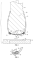
- no gasket is used, as the orientation of the stitch holes is such that they are displaced from the foot-receiving cavity by the upper and the strobel (i.e., the upper and the strobel themselves obstruct the stitch holes). More specifically, the inner surface of the strobel abuts an inner surface of the upper along a periphery of the strobel to define a peripheral flange. The stitch holes extend through the peripheral flange from the outer surface of the strobel to the outer surface of the upper and are displaced from the foot-receiving cavity.
- the peripheral flange extends away from the foot-receiving cavity, and the stitch holes do not extend toward or into the peripheral cavity in order to extend through the peripheral flange.
- a method of manufacturing an article of footwear comprises obstructing stitch holes that extend through a strobel.
- a series of stitches are disposed in the stitch holes and secure the strobel to an upper so that the strobel and the upper define a foot-receiving cavity.
- the method further comprises injecting a flowable polymeric material into a mold cavity configured as a midsole mold such that the a flowable polymeric material contacts an outer surface of the strobel. Obstructing the stitch holes inhibits the flowable polymeric material from passing through the strobel to the foot-receiving cavity via the stitch holes.
- the method may include stitching the strobel to the upper to establish the series of stitches and the stitch holes.
- the strobel may be positioned adjacent to the upper so that the strobel and the upper define the foot-receiving cavity with a first layer of the strobel disposed at the foot-receiving cavity of the upper and a second layer of the strobel is exposed.
- the method may comprise abutting an inner surface of the strobel to an inner surface of the upper along a periphery of the strobel to define a peripheral flange, and then the stitching results in the stitch holes extending through the peripheral flange from the outer surface of the strobel to the outer surface of the upper so that the stich holes are displaced from the foot-receiving cavity
- obstructing the stitch holes is by securing a gasket to the outer surface of the strobel over the stitch holes.
- securing the gasket to the strobel is by adhering the gasket to the strobel.
- securing the gasket to the strobel may be by thermally bonding the gasket to the strobel. The gasket seals those stitch holes over which it extends.
- the method may further comprise inserting a last in a foot-receiving cavity formed by the upper and the strobel prior to injecting the flowable polymeric material. While the last is inserted in the foot-receiving cavity, the method may include disposing a lower portion of the upper and the strobel in a mold cavity configured as a midsole mold. The method may include solidifying the flowable polymeric material in the mold cavity so that a midsole is secured to the upper and covers the gasket in embodiments that have a gasket, and covers the peripheral flange in embodiments that have a peripheral flange. The upper and the strobel with the midsole secured thereto may then be withdrawn from the mold cavity.
- FIG. 1 shows a portion of an article of footwear 10 that includes an upper 12, a strobel 14 stitched to the upper 12, and a gasket 16.
- the article of footwear 10 also includes a midsole 18, shown in FIG. 12 , that is secured to the strobel 14 and the upper 12 over the gasket 16 in a direct bottoming manufacturing process discussed herein.
- the upper 12 and the strobel 14 together define a foot-receiving cavity 20 that is configured to receive and retain a foot so that the foot is supported on the strobel 14 and the midsole 18 which are positioned below the foot and between the foot and the ground during normal wear.
- the upper 12 and the strobel 14 both include and extend in a forefoot region 22, a midfoot region 24, and a heel region 26 of the article of footwear 10.
- the midfoot region 24 is between the heel region 26 and the forefoot region 22.
- the forefoot region 22 generally underlies the toes and metatarsal-phalangeal joints of an overlying foot disposed in the foot-receiving cavity 20, the midfoot region 24 generally underlies the arch region of the foot, and the heel region 26 generally underlies the calcaneus bone of the foot.
- the position of a foot (not shown) is best represented by the footwear last 19 of FIG. 12 .
- the footwear last 19 is shaped and sized to be representative of a foot having the specific footwear size for which the article of footwear is dimensioned.
- the strobel 14 is specifically configured for a direct bottoming manufacturing process.
- the strobel 14 is relatively, thin, soft, and inelastic.
- the strobel 14 may be approximately one-fifth of the thickness of a traditional strobel, which may enhance its comfortable feel.
- the strobel 14 includes a first layer 30 and a second layer 32. When the strobel 14 is secured to the upper 12, an inner surface 34 of the first layer 30 is disposed at and defines the extremity of the foot-receiving cavity 20 which is completely filled by the last 19 in FIG. 8 .
- the first layer 30 may be a relatively thin, soft textile material that is thinner and softer than, for example, the textile material of a traditional strobel.
- the inner surface 34 may also be referred to as the foot-receiving surface as it is in direct contact with a foot (or a sock, if any is worn on the foot) when the article of footwear 10 is worn, as the article of footwear 10 is characterized by the absence of an insole.
- the first layer 30 is specifically selected to be soft for comfort during wear as the article of footwear 10 is configured to be worn without an insole.
- an outer surface 36 of the first layer 30 is secured to an inner surface 38 of the second layer 32, such as by adhesive bonding or thermal bonding.
- an outer surface 40 of the second layer 32 is exposed to the flowable polymeric material 17 in liquid form that is used to form the midsole 18, as described herein.
- the second layer 32 is a material specifically selected for its ability to inhibit or entirely prevent the flowable polymeric material 17 from penetrating the second layer 32.
- the second layer 32 may be a relatively thin polymeric film that functions as a barrier film with respect to the flowable polymeric material 17.
- the strobel 14 is stitched to the upper 12 at a series of stitches 42 that extend through stitch holes 44 in the strobel 14.
- the stitches 42 may be, for example, a portion of a continuous, elongated thread.
- the stitch holes 44 extend completely through the strobel 14 (i.e., through both the first layer 30 and the second layer 32 from the outer surface 40 to the inner surface 34), and also extend through the upper 12 along a lower periphery of the upper 12.
- the stitch holes 44 are made by a needle during the stitching process.
- the series of stitches 42 and the respective stitch holes 44 of the stitches border the perimeter 46 of the strobel 14 in the forefoot region 22, the midfoot region 24, and the heel region 26 along both a medial side 48 and a lateral side 50 of the strobel 14, around the foremost extent 52 of the forefoot region 22, and around the rearmost extent 54 of the heel region 26.
- the stitch holes 44 are obstructed such that the stitch holes 44 are not exposed to both the midsole 18 and the foot-receiving cavity 20. If the stitch holes 44 were to be exposed to the flowable polymeric material 17 used to form the midsole 18, they would provide a direct route for the flowable polymeric material to pass through the strobel 14 onto, for example, the inner surface 34 of the first layer 30. This may not be aesthetically pleasing given that no insole covers the inner surface 34.
- One way to obstruct the stitch holes 44 in order to avoid such a leakage route is to provide the gasket 16 that is configured to cover and seal at least some of the stitch holes 44, so that the function of the second layer 32 in inhibiting entry of the a flowable polymeric material 17 is not diminished.
- the gasket 16 is secured to the outer surface 40 of the strobel 14 over at least some of the stitch holes 44 as best shown in FIGS. 4 and 6 .
- the gasket 16 may be thermally bonded to the strobel 14. Alternatively, the gasket 16 may be self-adhering.
- the inner surface 56 of the gasket 16 contacts the outer surface 40 of the second layer 32 of the strobel 14 over the stitch holes 44, and the gasket 16 includes an adhesive on the inner surface 56 so that the inner surface 56 adheres to the strobel 14.
- the gasket 16 is configured of a material impenetrable to a flowable polymeric material 17 so that it inhibits or entirely prevents the a flowable polymeric material 17 from passing through the gasket 16.
- the gasket 16 is a flat, elongated strip and is wide enough to cover the stitch holes 44 and may also be wide enough to cover a portion of the lower extent of the upper 12 where the stitches 42 enter through the upper 12, as shown in FIGS. 6 and 9 .
- the gasket 16 has a U-shaped heel portion 60, a medial arm portion 62 (also referred to as a medial portion) extending forward from the U-shaped heel portion 60, and a lateral arm portion 64 (also referred to as a lateral portion) extending forward from the U-shaped heel portion 60.
- the U-shaped heel portion 60 extends in the heel region 26, and the medial and lateral arm portions 62, 64 extend in the midfoot region 24 and in a rear portion of the forefoot region 22.
- the gasket 16 is much narrower than the width of the strobel 14 from the medial side 48 of its perimeter 46 to the lateral side 50 of its perimeter 46.
- the medial arm portion 62 extends over the stitch holes 44 at the medial side 48 of the strobel 14, and the lateral arm portion 64 extends over the stitch holes 44 at the lateral side 50 of the strobel 14.
- the gasket 16 does not obstruct all of the stitch holes 44, however, as the gasket 16 does not extend around the entire perimeter 46.
- the medial arm portion and the lateral arm portion 62, 64 terminate rearward of the foremost extent of the strobel 14, so that a some of the stitch holes 44 (i.e., as sub-set of the stitch holes 44) forward of the medial arm portion and the lateral arm portion 62, 64 are exposed at the outer surface 40 of the strobel 14 before the midsole 18 is secured to the strobel 14, as shown in FIG. 4 .
- the stitch holes of the exposed sub-set are indicated with reference number 44A in FIG. 4 .
- the flowable polymeric material 17 may extend through these stitch holes 44A during the direct bottoming process, the inner surface 34 of the strobel at this forward extent of the forefoot region 22 may be difficult to view within the foot-receiving cavity 20, and the aesthetic qualities of the footwear 10 will thus not be diminished.
- FIG. 7 shows an alternative embodiment of an article of footwear 110, alike in all aspects to the article of footwear 10, except that the gasket 16 is replaced by a gasket 116 identical to gasket 16 except that it extends around the entire perimeter 46 of the strobel 14 and covers all of the stitch holes 44.
- FIGS. 1 and 7 show that a portion of the outer surface 40 of the strobel 14 is exposed between the gasket 16 or 116 at the medial side 48 and at the lateral side 50, such as between the medial arm portion 62 and the lateral arm portion 64. As best shown in FIG. 12 , this portion of the outer surface 40 is thus exposed to the flowable polymeric material 17 during the direct bottoming manufacturing process disclosed herein, and interfaces with the solidified midsole 18 which bonds to the upper 12 around the strobel 14. The bonding may occur by heat bonding (i.e., thermal bonding) during the manufacturing process described herein.
- FIGS. 14-17 show a strobel 14 stitched to an upper 12 and disposed on a last 19 according to an example for better understanding the claimed invention that is not covered by the claims.
- a peripheral portion 34A of the inner surface 34 of the strobel 14 abuts the inner surface 35 of the upper at or near the perimeter 46 of the strobel 14 and a lower portion 12A of the upper 12.
- the stitches 42 extend through the abutting portions of the strobel 14 and the upper 12 to form a peripheral flange 15.
- the stitch holes 44 extend from the outer surface 40 of the strobel 14 to the outer surface 37 of the upper 12 through the peripheral flange 15.
- the stitch holes 44 are oriented so that they do not extend toward or into the foot-receiving cavity 20 and thus do not create a path for the flowable polymeric material 17 to reach the inner surface 34 of the first layer 30 at the foot-receiving cavity 20 during manufacturing.
- the peripheral flange 15 extends away from the foot-receiving cavity 20, not into the foot-receiving cavity 20. Accordingly, no gasket 16 or 116 is needed in this example.
- the peripheral flange 15 is covered by the midsole 18.
- FIGS. 8-12 illustrate the steps of a method 200 of manufacturing an article of footwear such as article of footwear 10, 110, or 310.
- the steps of the method 200 are listed in the flow diagram of FIG. 13 .
- the method 200 begins with step 202, positioning the strobel 14 adjacent to the upper 12 so that the first layer 30 of the strobel 14 is disposed at the foot-receiving cavity 20 of the upper 12, and the second layer 32 of the strobel 14 is exposed (i.e., at an exterior of the connected upper 12 and strobel 14).
- the strobel 14 is subsequently stitched to the upper 12 in step 204.
- the strobel 14 is stitched to the upper 12 at a series of stitches 42 that secure the strobel 14 to the upper 12.
- the stitches 42 secure the strobel 14 to the upper 12 but create stitch holes 44 in the strobel 14.
- step 204 results in the obstructing of the stitch holes 44 to inhibit the flowable polymeric material 17 from passing through the strobel 14 to the foot-receiving cavity 20 via the stitch holes 44 during step 212 and specifically sub-step 214.
- obstructing the stitch holes 44 includes both step 204 and step 206 in which the gasket 16 or 116 is secured to the strobel 14 over the series of stitches 42 so that the gasket seals at least some of the stitch holes 44 in the strobel 14 as shown in FIGS. 1 and 7 .
- Non-limiting examples of ways by which the gasket 16 or 116 may be secured to the strobel include adhering the gasket 16 or 116 to the strobel 14, or thermally bonding the gasket 16 or 116 to the strobel 14. Step 206 is skipped in the manufacturing of the article of footwear 310.
- the upper 12 and the strobel 14 are ready to be lasted in step 208 by inserting a last 19 in the foot-receiving cavity 20 formed by the upper 12 and the strobel 14 as shown in FIGS. 8 and 14 .
- the upper 12 and strobel 14 may be adjusted to a predetermined position on the last 19, such as may be indicated by alignment features on the strobel 14 aligning with markings on the last 19.
- step 210 disposing a lower portion 12A of the upper 12 and the strobel 14 into a mold cavity 70 formed in part by a first mold portion 72 of a mold assembly 73.
- Step 210 is illustrated in FIGS. 8 , 10 , 14 and 16 .
- the last 19 with the upper 12 and strobel 14 thereon are moved toward the mold cavity 70 as indicated by arrow A.
- the mold assembly 73 is closed such as by moving a second mold portion 74 into place around the upper 12 and last 19 at the mold cavity 70 to further define the mold cavity 70 as shown in FIGS. 10 and 16 .
- the mold cavity 70 is configured in the shape of the midsole 18, and may be referred to as a midsole mold.
- the gasket 16, 116 and the peripheral flange 15 are disposed in the mold cavity via step 210.
- Step 212 the midsole 18 is injection molded so that it will secure to the upper 12 and the strobel 14 over the gasket 16 or 116 or the peripheral flange 15.
- Step 212 includes sub-step 214, injecting a flowable polymeric material 17 in liquid form into the mold cavity 70.
- This is referred to as a direct bottoming process, as the midsole 18 is directly formed from a flowable polymeric material 17on the bottom of the strobel 14 and the upper 12, instead of being pre-formed and then attached with adhesive or by thermal processes.
- FIGS. 11 and 16 shows the a flowable polymeric material 17 directed into the mold cavity 70 from a supply 80 of the flowable polymeric material, as indicated by arrow B, such as by pumping the flowable polymeric material 17.
- the gasket 16, 116 secured over the stitch holes 44 or the peripheral flange 15 is exposed to the flowable polymeric material 17 in the mold cavity 70 and prevents flowable polymeric material injection-molded in the mold cavity 70 for the midsole 18 from entering the stitch holes 44 during the direct bottoming process.
- Step 212 also includes sub-step 216, solidifying the flowable polymeric material in the mold cavity 70 so that the polymeric material is formed as the midsole 18 secured to the upper 12 and the strobel 14 and covering over the gasket 16 or 116 or the peripheral flange 15.
- Solidifying the flowable polymeric material in sub-step 216 may include waiting a predetermined time period for the liquid flowable polymeric material 17 to solidify, and may also include controlling and/or monitoring the temperature of the polymeric material in the mold cavity 70.
- Step 218, in which the lower extent of the upper 12, the strobel 14 with the gasket 16 or 116 or the peripheral flange 15 and the midsole 18 secured thereto are withdrawn from the mold cavity 70 as illustrated in FIGS. 12 and 17 .
- Step 218 may include the sub-steps of opening the mold assembly 73 and moving the last 19 away from the mold assembly 73.
- the article of footwear 10, 110, or 310 may then be removed from the last 19. Additional steps such as securing an outsole or discrete outsole elements to the midsole 18 may be carried out after step 218, either while the article of footwear 10, 110, or 310 is on the last 19 or after the article of footwear is removed from the last 19.
- An "article of footwear”, a “footwear article of manufacture”, and “footwear” may be considered to be both a machine and a manufacture. Assembled, ready to wear footwear articles (e.g., shoes, sandals, boots, etc.), as well as discrete components of footwear articles (such as a midsole, an outsole, an upper component, etc.) prior to final assembly into ready to wear footwear articles, are considered and alternatively referred to herein in either the singular or plural as “article(s) of footwear” or "footwear”.
- footwear articles e.g., shoes, sandals, boots, etc.
- discrete components of footwear articles such as a midsole, an outsole, an upper component, etc.
- longitudinal refers to a direction extending a length of a component.
- a longitudinal direction of an article of footwear extends between a forefoot region and a heel region of the article of footwear.
- forward or “anterior” is used to refer to the general direction from a heel region toward a forefoot region
- rearward or “posterior” is used to refer to the opposite direction, i.e., the direction from the forefoot region toward the heel region.
- a component may be identified with a longitudinal axis as well as a forward and rearward longitudinal direction along that axis.
- the longitudinal direction or axis may also be referred to as an anterior-posterior direction or axis.
- transverse refers to a direction extending a width of a component.
- a transverse direction of an article of footwear extends between a lateral side and a medial side of the article of footwear.
- the transverse direction or axis may also be referred to as a lateral direction or axis or a mediolateral direction or axis.
- vertical refers to a direction generally perpendicular to both the lateral and longitudinal directions. For example, in cases where a sole structure is planted flat on a ground surface, the vertical direction may extend from the ground surface upward. It will be understood that each of these directional adjectives may be applied to individual components of a sole structure.
- upward or “upwards” refers to the vertical direction pointing towards a top of the component, which may include an instep, a fastening region and/or a throat of an upper.
- downward or “downwards” refers to the vertical direction pointing opposite the upwards direction, toward the bottom of a component and may generally point towards the bottom of a sole structure of an article of footwear.
- the "interior" of an article of footwear refers to portions at the space that is occupied by a wearer's foot when the article of footwear is worn.
- the “inner side” of a component refers to the side or surface of the component that is (or will be) oriented toward the interior of the component or article of footwear in an assembled article of footwear.
- the “outer side” or “exterior” of a component refers to the side or surface of the component that is (or will be) oriented away from the interior of the article of footwear in an assembled article of footwear. In some cases, other components may be between the inner side of a component and the interior in the assembled article of footwear.
- other components may be between an outer side of a component and the space external to the assembled article of footwear.
- the terms “inward” and “inwardly” refer to the direction toward the interior of the component or article of footwear, such as a shoe
- the terms “outward” and “outwardly” refer to the direction toward the exterior of the component or article of footwear, such as the shoe.
- proximal refers to a direction that is nearer a center of a footwear component, or is closer toward a foot when the foot is inserted in the article of footwear as it is worn by a user.
- distal refers to a relative position that is further away from a center of the footwear component or is further from a foot when the foot is inserted in the article of footwear as it is worn by a user.
- proximal and distal may be understood to provide generally opposing terms to describe relative spatial positions.
Landscapes
- Engineering & Computer Science (AREA)
- Mechanical Engineering (AREA)
- Footwear And Its Accessory, Manufacturing Method And Apparatuses (AREA)
Claims (14)
- Ein Verfahren zur Herstellung eines Fußbekleidungsartikels (10), das Folgendes umfasst:Blockieren bzw. Versperren (obstructing) von Stichlöchern (44), die sich durch einen Strobel (14) erstrecken; wobei eine Reihe von Nähten bzw. Stichen (stitches) (42) in den Stichlöchern (44) angeordnet sind und den Strobel (14) an einem Oberteil (12) befestigen, sodass der Strobel (14) und das Oberteil (12) einen Fußaufnahmehohlraum (20) definieren; wobei das Versperren der Stichlöcher (44) durch Befestigen einer Dichtung (16) an der Außenfläche (40) des Strobel (14) über den Stichlöchern (44) erfolgt; undEinspritzen eines fließfähigen Polymermaterials (17) in einen Formhohlraum (70), der als eine Zwischensohlenform konfiguriert ist, sodass das fließfähige Polymermaterial (17) eine Außenfläche (40) des Strobel (14) berührt; wobei das Versperren der Stichlöcher (44) das fließfähige polymere Material (17) daran hindert, durch den Strobel (14) über die Stichlöcher (44) in den Fußaufnahmehohlraum (20) zu gelangen.
- Das Verfahren nach Anspruch 1, wobei das Befestigen der Dichtung (16) an der Außenfläche (40) des Strobel (14) durch Verkleben der Dichtung (16) mit dem Strobel (14) oder durch thermisches Verbinden der Dichtung (16) mit der Außenfläche (40) des Strobel (14) erfolgt.
- Das Verfahren nach irgendeinem der Ansprüche von 1 bis 2, wobei:die Reihe von Stichen (42) einen Umfang des Strobel (14) in einem Vorderfußbereich (22), einem Mittelfußbereich (24) und einem Fersenbereich (26) des Strobel (14) begrenzt; und wobeidie Dichtung (16) sich über Stichlöcher (44) im Fersenbereich (26) und im Mittelfußbereich (24) erstreckt.
- Das Verfahren nach Anspruch 3, wobei sich die Dichtung (16) ferner über die Stichlöcher (44) im Vorderfußbereich (22) erstreckt.
- Das Verfahren nach irgendeinem der Ansprüche von 1 bis 4, wobei:die Dichtung (16) ein flacher, länglicher Streifen mit einem U-förmigen Fersenabschnitt (60), einem medialen Armabschnitt (62), der sich von dem U-förmigen Fersenabschnitt (60) nach vorne erstreckt, und einem lateralen Armabschnitt (64) ist, der sich vom U-förmigen Fersenabschnitt (60) nach vorne erstreckt;der mediale Armabschnitt (62) und der laterale Armabschnitt (64) hinter einer vordersten Ausdehnung des Strobel (14) enden; und wobeimindestens einige der Stichlöcher (44), an denen der Strobel (14) mit dem Oberteil (12) vernäht ist, vor dem medialen Armabschnitt (62) und dem lateralen Armabschnitt (64) liegen.
- Das Verfahren nach Anspruch 1, das ferner Folgendes umfasst:
Annähen des Strobel (14) an das Oberteil (12), um die Reihe von Stichen (42) und die Stichlöcher (44) herzustellen. - Das Verfahren nach Anspruch 6, das ferner Folgendes umfasst:vor dem Annähen des Strobel (14) an das Oberteil (12), Anlegen einer Innenfläche (34) des Strobel (14) an eine Innenfläche des Oberteils (12) entlang eines Umfangs des Strobel (14), um einen Umfangsflansch (15) zu definieren; undwobei sich die Stichlöcher (44) durch den Umfangsflansch (15) von der Außenfläche (40) des Strobel (14) zu der Außenfläche des Oberteils (12) erstrecken und relativ zum Fußaufnahmehohlraum (20) versetzt sind.
- Das Verfahren nach Anspruch 6, wobei der Strobel (14) eine erste Schicht (80) und eine zweite Schicht (32) beinhaltet, wobei die zweite Schicht (32) ein Material umfasst, das das fließfähige polymere Material (17) daran hindert, die zweite Schicht (32) zu durchdringen, und wobei das Verfahren ferner Folgendes beinhaltet:
vor dem Annähen des Strobel (14) an das Oberteil (12), Positionieren des Strobel (14) anliegend am Oberteil (12), sodass der Strobel (14) und das Oberteil (12) den Fußaufnahmehohlraum (20) definieren, wobei die erste Schicht (30) am Fußaufnahmehohlraum (20) angeordnet ist und die zweite Schicht (32) freiliegt. - Das Verfahren nach Anspruch 6, das ferner Folgendes umfasst:
vor dem Einspritzen des fließfähigen Polymermaterials (17):Einsetzen eines Leistens (19) in den Fußaufnahmehohlraum (20); undAnordnen des Strobel (14) und eines unteren Abschnitts des Oberteils (12) im Formhohlraum (70). - Das Verfahren nach Anspruch 9, das ferner Folgendes umfasst:
Einstellen des Oberteils (12) und des Strobel (14) in eine vorbestimmte Position auf dem Leisten (19); wobei die vorbestimmte Position durch Ausrichtungsmerkmale auf dem Strobel (14) und Markierungen auf dem Leisten (19) angezeigt wird. - Das Verfahren nach irgendeinem der Ansprüche von 9 bis 10, das ferner Folgendes umfasst:Verfestigen des fließfähigen Polymermaterials (17) im Formhohlraum (70), um eine Zwischensohle (18) zu bilden, die am Oberteil (12) befestigt ist; undHerausziehen des Strobel (14), des unteren Abschnitt des Oberteils (12) und der Zwischensohle aus dem Formhohlraum (70).
- Das Verfahren nach Anspruch 11, wobei die Außenfläche (40) des Strobel (14) direkt an der Zwischensohle (18) befestigt ist.
- Das Verfahren nach Anspruch 11, wobei:
nach dem Befestigen der Dichtung (16) an der Außenfläche (40) des Strobel (14) über den Stichlöchern (44), das Verfahren (200) mit dem Anordnen des Strobel (14) und des unteren Abschnitts (12A) des Oberteils (12) im Formhohlraum (70) fortfährt. - Das Verfahren nach Anspruch 13, wobei:ein medialer Abschnitt der Dichtung (16) sich über die Stichlöcher (44) an einer medialen Seite des Strobel (14) erstreckt und ein lateraler Abschnitt der Dichtung (16) sich über die Stichlöcher (44) an einer lateralen Seite des Strobel (14) erstreckt; und wobeidie Außenfläche (40) des Strobel (14) der Zwischensohle ausgesetzt ist und zwar zwischen dem medialen Abschnitt der Dichtung (16) und dem lateralen Abschnitt der Dichtung (16).
Applications Claiming Priority (3)
| Application Number | Priority Date | Filing Date | Title |
|---|---|---|---|
| US201862678252P | 2018-05-30 | 2018-05-30 | |
| PCT/US2019/034126 WO2019231882A1 (en) | 2018-05-30 | 2019-05-28 | Article of footwear and method of manufacturing an article of footwear |
| EP19730650.9A EP3801112B1 (de) | 2018-05-30 | 2019-05-28 | Schuhartikel und verfahren zur herstellung eines schuhartikels |
Related Parent Applications (1)
| Application Number | Title | Priority Date | Filing Date |
|---|---|---|---|
| EP19730650.9A Division EP3801112B1 (de) | 2018-05-30 | 2019-05-28 | Schuhartikel und verfahren zur herstellung eines schuhartikels |
Publications (2)
| Publication Number | Publication Date |
|---|---|
| EP4205592A1 EP4205592A1 (de) | 2023-07-05 |
| EP4205592B1 true EP4205592B1 (de) | 2024-09-04 |
Family
ID=66858040
Family Applications (2)
| Application Number | Title | Priority Date | Filing Date |
|---|---|---|---|
| EP19730650.9A Active EP3801112B1 (de) | 2018-05-30 | 2019-05-28 | Schuhartikel und verfahren zur herstellung eines schuhartikels |
| EP23158014.3A Active EP4205592B1 (de) | 2018-05-30 | 2019-05-28 | Verfahren zur herstellung eines schuhartikels |
Family Applications Before (1)
| Application Number | Title | Priority Date | Filing Date |
|---|---|---|---|
| EP19730650.9A Active EP3801112B1 (de) | 2018-05-30 | 2019-05-28 | Schuhartikel und verfahren zur herstellung eines schuhartikels |
Country Status (4)
| Country | Link |
|---|---|
| US (2) | US11129441B2 (de) |
| EP (2) | EP3801112B1 (de) |
| CN (1) | CN112153915A (de) |
| WO (1) | WO2019231882A1 (de) |
Families Citing this family (6)
| Publication number | Priority date | Publication date | Assignee | Title |
|---|---|---|---|---|
| US10842221B2 (en) * | 2017-08-10 | 2020-11-24 | Converse Inc. | Method of forming a strobel |
| US11129441B2 (en) * | 2018-05-30 | 2021-09-28 | Nike, Inc. | Article of footwear and method of manufacturing an article of footwear |
| CN115137122A (zh) * | 2018-05-31 | 2022-10-04 | 耐克创新有限合伙公司 | 带有囊和拉伸部件的鞋类中底布和制造方法 |
| KR102677343B1 (ko) * | 2018-05-31 | 2024-06-20 | 나이키 이노베이트 씨.브이. | 블래더 및 라스팅 구성요소를 구비한 신발류 스트로벨 및 제조 방법 |
| CN115177070B (zh) * | 2018-05-31 | 2024-09-27 | 耐克创新有限合伙公司 | 带有具有凹槽凸缘的囊的鞋类斯创贝尔及制造方法 |
| WO2022189447A1 (en) | 2021-03-12 | 2022-09-15 | Basf Se | Strobel for an article of footwear, an article of footwear and process for manufacturing the article of footwear |
Family Cites Families (38)
| Publication number | Priority date | Publication date | Assignee | Title |
|---|---|---|---|---|
| DE278305C (de) | ||||
| US967575A (en) * | 1909-02-03 | 1910-08-16 | John Seitz | Liquor aging and processing apparatus. |
| GB2132554B (en) * | 1982-12-17 | 1986-10-01 | British United Shoe Machinery | Shoe insole and the manufacture thereof |
| US4603075A (en) * | 1984-04-10 | 1986-07-29 | Texon, Inc. | Insole composites and processes for manufacturing insole composites and footwear materials |
| US4852275A (en) * | 1986-09-25 | 1989-08-01 | Highland Import Corporation | Shoe having a rigid back part |
| US4704808A (en) | 1986-09-25 | 1987-11-10 | Highland Import Corporation | Shoe having a rigid back part and flexible forepart |
| US4809447A (en) * | 1987-11-13 | 1989-03-07 | W. L. Gore & Associates, Inc. | Waterproof breathable sock |
| DD278305A1 (de) * | 1988-12-20 | 1990-05-02 | Fi F Leder U Kunst Ledertechno | Sperrschichtmaterial und seine verwendung |
| US6258421B1 (en) | 1993-07-23 | 2001-07-10 | Nike, Inc. | Bladder and method of making the same |
| JPH08224110A (ja) * | 1995-02-21 | 1996-09-03 | Asahi Corp | 防水靴の射出成形法 |
| US5664343A (en) * | 1995-05-19 | 1997-09-09 | The Rockport Company, Inc. | Shoe having a waterproof liner |
| WO2001021023A1 (en) * | 1999-09-21 | 2001-03-29 | Nottington Holding B.V. | Waterproof and moisture-permeable shoe and method for manufacture thereof |
| US6402879B1 (en) | 2000-03-16 | 2002-06-11 | Nike, Inc. | Method of making bladder with inverted edge seam |
| IT1317329B1 (it) | 2000-04-13 | 2003-06-16 | Nottington Holding Bv | Calzatura traspirante. |
| FR2825241B1 (fr) | 2001-06-05 | 2004-07-23 | Promiles | Chaussure impermeable a semelle injectee sur tige |
| DE10207663C1 (de) * | 2002-02-22 | 2003-08-28 | Gore W L & Ass Gmbh | Schuhschaft und damit aufgebautes Schuhwerk und Verfahren zu deren Herstellung |
| DE50203449D1 (de) * | 2002-03-01 | 2005-07-28 | Sympatex Technologies Gmbh | Verfahren zur Herstellung eines wasserdichten Schuhwerkes sowie Schuhwerk |
| US20040049942A1 (en) * | 2002-09-18 | 2004-03-18 | Eddie Chen | Shoe having waterproof breathable shell |
| US7055267B2 (en) * | 2003-04-30 | 2006-06-06 | Bha Technologies, Inc. | Waterproof footwear construction |
| US7752772B2 (en) | 2006-01-24 | 2010-07-13 | Nike, Inc. | Article of footwear having a fluid-filled chamber with flexion zones |
| ITPD20060274A1 (it) * | 2006-07-06 | 2008-01-07 | Geox Spa | Calzatura, del tipo impermeabile all'acqua e permeabile al vapore acqueo |
| FR2903866B1 (fr) * | 2006-07-21 | 2009-03-20 | Salomon Sa | Chaussure respiro-etanche |
| US7836609B2 (en) * | 2007-04-09 | 2010-11-23 | Columbia Insurance Company | Method and apparatus for a shoe with improved construction |
| ME02714B (de) * | 2009-08-28 | 2015-04-30 | Geox Spa | Dampfdurchlässiger Schuh |
| FR2952790B1 (fr) * | 2009-11-23 | 2012-01-06 | Salomon Sas | Chaussure a semelage ameliore |
| IT1398094B1 (it) * | 2010-02-10 | 2013-02-07 | Geox Spa | Calzatura con tomaia e suola impermeabili |
| US8595878B2 (en) | 2010-08-02 | 2013-12-03 | Nike, Inc. | Method of lasting an article of footwear |
| US8839530B2 (en) | 2011-04-12 | 2014-09-23 | Nike, Inc. | Method of lasting an article of footwear with a fluid-filled chamber |
| US8595956B2 (en) * | 2011-09-29 | 2013-12-03 | C. & J. Clark International Limited | Footwear with elastic footbed cover and soft foam footbed |
| US20130232818A1 (en) | 2012-03-07 | 2013-09-12 | W.L. Gore & Associates, Inc. | Strobel Footwear Construction |
| US20130232825A1 (en) * | 2012-03-07 | 2013-09-12 | W. L. Gore & Associates, Inc. | Stretchable Insole |
| US9155357B2 (en) | 2012-09-11 | 2015-10-13 | Nike, Inc. | Automated strobel printing |
| US9427043B2 (en) | 2013-10-31 | 2016-08-30 | Nike, Inc. | Fluid-filled chamber with stitched tensile member |
| US9468258B2 (en) | 2014-03-14 | 2016-10-18 | Wolverine Outdoors, Inc. | Footwear including combination lasting construction |
| WO2015200713A1 (en) | 2014-06-25 | 2015-12-30 | Fuerst Group, Inc. | Strobel lasted injected footwear |
| US9474326B2 (en) | 2014-07-11 | 2016-10-25 | Nike, Inc. | Footwear having auxetic structures with controlled properties |
| US20160302517A1 (en) | 2015-04-17 | 2016-10-20 | Wolverine World Wide, Inc. | Sole assembly for an article of footwear |
| US11129441B2 (en) * | 2018-05-30 | 2021-09-28 | Nike, Inc. | Article of footwear and method of manufacturing an article of footwear |
-
2019
- 2019-05-28 US US16/423,616 patent/US11129441B2/en active Active
- 2019-05-28 CN CN201980032084.8A patent/CN112153915A/zh active Pending
- 2019-05-28 EP EP19730650.9A patent/EP3801112B1/de active Active
- 2019-05-28 WO PCT/US2019/034126 patent/WO2019231882A1/en not_active Ceased
- 2019-05-28 EP EP23158014.3A patent/EP4205592B1/de active Active
-
2021
- 2021-09-01 US US17/463,656 patent/US12144396B2/en active Active
Also Published As
| Publication number | Publication date |
|---|---|
| CN112153915A (zh) | 2020-12-29 |
| US20210392998A1 (en) | 2021-12-23 |
| US11129441B2 (en) | 2021-09-28 |
| EP3801112A1 (de) | 2021-04-14 |
| US20190365046A1 (en) | 2019-12-05 |
| EP4205592A1 (de) | 2023-07-05 |
| US12144396B2 (en) | 2024-11-19 |
| WO2019231882A1 (en) | 2019-12-05 |
| EP3801112B1 (de) | 2023-03-08 |
Similar Documents
| Publication | Publication Date | Title |
|---|---|---|
| EP4205592B1 (de) | Verfahren zur herstellung eines schuhartikels | |
| US20250160482A1 (en) | Sole for Sports Shoes | |
| US20230301396A1 (en) | Footwear with jointed sole structure for ease of access | |
| US6604302B2 (en) | Waterproof shoe with sole or mid-sole molded onto the upper | |
| CN108348044B (zh) | 用于具有模制鞋底的鞋的针织鞋面和鞋 | |
| US10499706B2 (en) | Molded footwear upper and method of making same | |
| US20210085021A1 (en) | Footwear sole structure and upper with an embedded plate | |
| US10016011B2 (en) | Injected footwear | |
| US10362835B2 (en) | Strobel lasted injected footwear | |
| CN101460072A (zh) | 用于鞋类物品和其它容纳脚装置的内部件和鞋面构件 | |
| US6018891A (en) | Shoe construction | |
| US20220087362A1 (en) | Footwear sole structure and upper with an embedded plate | |
| US20120317836A1 (en) | Method For Assembling A Tongue For An Article Of Footwear | |
| WO2015028045A1 (en) | Footwear with air permeable layer in a lower peripheral area of the upper assembly and manufacturing method thereof | |
| EP3890547B1 (de) | Fussbekleidungsartikel mit einer bequemen und schützenden zehenkappe | |
| RU2793534C2 (ru) | Подошва для защитной обуви и способ изготовления такой подошвы | |
| WO2019219610A1 (en) | Footwear obtained by goodyear manufacture and method for the production of said footwear |
Legal Events
| Date | Code | Title | Description |
|---|---|---|---|
| PUAI | Public reference made under article 153(3) epc to a published international application that has entered the european phase |
Free format text: ORIGINAL CODE: 0009012 |
|
| STAA | Information on the status of an ep patent application or granted ep patent |
Free format text: STATUS: THE APPLICATION HAS BEEN PUBLISHED |
|
| AC | Divisional application: reference to earlier application |
Ref document number: 3801112 Country of ref document: EP Kind code of ref document: P |
|
| AK | Designated contracting states |
Kind code of ref document: A1 Designated state(s): AL AT BE BG CH CY CZ DE DK EE ES FI FR GB GR HR HU IE IS IT LI LT LU LV MC MK MT NL NO PL PT RO RS SE SI SK SM TR |
|
| STAA | Information on the status of an ep patent application or granted ep patent |
Free format text: STATUS: REQUEST FOR EXAMINATION WAS MADE |
|
| 17P | Request for examination filed |
Effective date: 20231221 |
|
| RBV | Designated contracting states (corrected) |
Designated state(s): AL AT BE BG CH CY CZ DE DK EE ES FI FR GB GR HR HU IE IS IT LI LT LU LV MC MK MT NL NO PL PT RO RS SE SI SK SM TR |
|
| GRAP | Despatch of communication of intention to grant a patent |
Free format text: ORIGINAL CODE: EPIDOSNIGR1 |
|
| STAA | Information on the status of an ep patent application or granted ep patent |
Free format text: STATUS: GRANT OF PATENT IS INTENDED |
|
| INTG | Intention to grant announced |
Effective date: 20240403 |
|
| P01 | Opt-out of the competence of the unified patent court (upc) registered |
Effective date: 20240522 |
|
| GRAS | Grant fee paid |
Free format text: ORIGINAL CODE: EPIDOSNIGR3 |
|
| GRAA | (expected) grant |
Free format text: ORIGINAL CODE: 0009210 |
|
| STAA | Information on the status of an ep patent application or granted ep patent |
Free format text: STATUS: THE PATENT HAS BEEN GRANTED |
|
| AC | Divisional application: reference to earlier application |
Ref document number: 3801112 Country of ref document: EP Kind code of ref document: P |
|
| AK | Designated contracting states |
Kind code of ref document: B1 Designated state(s): AL AT BE BG CH CY CZ DE DK EE ES FI FR GB GR HR HU IE IS IT LI LT LU LV MC MK MT NL NO PL PT RO RS SE SI SK SM TR |
|
| REG | Reference to a national code |
Ref country code: GB Ref legal event code: FG4D |
|
| REG | Reference to a national code |
Ref country code: CH Ref legal event code: EP |
|
| REG | Reference to a national code |
Ref country code: IE Ref legal event code: FG4D |
|
| REG | Reference to a national code |
Ref country code: DE Ref legal event code: R096 Ref document number: 602019058576 Country of ref document: DE |
|
| REG | Reference to a national code |
Ref country code: LT Ref legal event code: MG9D |
|
| REG | Reference to a national code |
Ref country code: NL Ref legal event code: MP Effective date: 20240904 |
|
| PG25 | Lapsed in a contracting state [announced via postgrant information from national office to epo] |
Ref country code: NO Free format text: LAPSE BECAUSE OF FAILURE TO SUBMIT A TRANSLATION OF THE DESCRIPTION OR TO PAY THE FEE WITHIN THE PRESCRIBED TIME-LIMIT Effective date: 20241204 |
|
| PG25 | Lapsed in a contracting state [announced via postgrant information from national office to epo] |
Ref country code: GR Free format text: LAPSE BECAUSE OF FAILURE TO SUBMIT A TRANSLATION OF THE DESCRIPTION OR TO PAY THE FEE WITHIN THE PRESCRIBED TIME-LIMIT Effective date: 20241205 Ref country code: FI Free format text: LAPSE BECAUSE OF FAILURE TO SUBMIT A TRANSLATION OF THE DESCRIPTION OR TO PAY THE FEE WITHIN THE PRESCRIBED TIME-LIMIT Effective date: 20240904 |
|
| PG25 | Lapsed in a contracting state [announced via postgrant information from national office to epo] |
Ref country code: BG Free format text: LAPSE BECAUSE OF FAILURE TO SUBMIT A TRANSLATION OF THE DESCRIPTION OR TO PAY THE FEE WITHIN THE PRESCRIBED TIME-LIMIT Effective date: 20240904 |
|
| PG25 | Lapsed in a contracting state [announced via postgrant information from national office to epo] |
Ref country code: LV Free format text: LAPSE BECAUSE OF FAILURE TO SUBMIT A TRANSLATION OF THE DESCRIPTION OR TO PAY THE FEE WITHIN THE PRESCRIBED TIME-LIMIT Effective date: 20240904 |
|
| PG25 | Lapsed in a contracting state [announced via postgrant information from national office to epo] |
Ref country code: HR Free format text: LAPSE BECAUSE OF FAILURE TO SUBMIT A TRANSLATION OF THE DESCRIPTION OR TO PAY THE FEE WITHIN THE PRESCRIBED TIME-LIMIT Effective date: 20240904 |
|
| PG25 | Lapsed in a contracting state [announced via postgrant information from national office to epo] |
Ref country code: ES Free format text: LAPSE BECAUSE OF FAILURE TO SUBMIT A TRANSLATION OF THE DESCRIPTION OR TO PAY THE FEE WITHIN THE PRESCRIBED TIME-LIMIT Effective date: 20240904 Ref country code: RS Free format text: LAPSE BECAUSE OF FAILURE TO SUBMIT A TRANSLATION OF THE DESCRIPTION OR TO PAY THE FEE WITHIN THE PRESCRIBED TIME-LIMIT Effective date: 20241204 |
|
| PG25 | Lapsed in a contracting state [announced via postgrant information from national office to epo] |
Ref country code: RS Free format text: LAPSE BECAUSE OF FAILURE TO SUBMIT A TRANSLATION OF THE DESCRIPTION OR TO PAY THE FEE WITHIN THE PRESCRIBED TIME-LIMIT Effective date: 20241204 Ref country code: NO Free format text: LAPSE BECAUSE OF FAILURE TO SUBMIT A TRANSLATION OF THE DESCRIPTION OR TO PAY THE FEE WITHIN THE PRESCRIBED TIME-LIMIT Effective date: 20241204 Ref country code: LV Free format text: LAPSE BECAUSE OF FAILURE TO SUBMIT A TRANSLATION OF THE DESCRIPTION OR TO PAY THE FEE WITHIN THE PRESCRIBED TIME-LIMIT Effective date: 20240904 Ref country code: HR Free format text: LAPSE BECAUSE OF FAILURE TO SUBMIT A TRANSLATION OF THE DESCRIPTION OR TO PAY THE FEE WITHIN THE PRESCRIBED TIME-LIMIT Effective date: 20240904 Ref country code: GR Free format text: LAPSE BECAUSE OF FAILURE TO SUBMIT A TRANSLATION OF THE DESCRIPTION OR TO PAY THE FEE WITHIN THE PRESCRIBED TIME-LIMIT Effective date: 20241205 Ref country code: FI Free format text: LAPSE BECAUSE OF FAILURE TO SUBMIT A TRANSLATION OF THE DESCRIPTION OR TO PAY THE FEE WITHIN THE PRESCRIBED TIME-LIMIT Effective date: 20240904 Ref country code: ES Free format text: LAPSE BECAUSE OF FAILURE TO SUBMIT A TRANSLATION OF THE DESCRIPTION OR TO PAY THE FEE WITHIN THE PRESCRIBED TIME-LIMIT Effective date: 20240904 Ref country code: BG Free format text: LAPSE BECAUSE OF FAILURE TO SUBMIT A TRANSLATION OF THE DESCRIPTION OR TO PAY THE FEE WITHIN THE PRESCRIBED TIME-LIMIT Effective date: 20240904 |
|
| REG | Reference to a national code |
Ref country code: AT Ref legal event code: MK05 Ref document number: 1719436 Country of ref document: AT Kind code of ref document: T Effective date: 20240904 |
|
| PG25 | Lapsed in a contracting state [announced via postgrant information from national office to epo] |
Ref country code: NL Free format text: LAPSE BECAUSE OF FAILURE TO SUBMIT A TRANSLATION OF THE DESCRIPTION OR TO PAY THE FEE WITHIN THE PRESCRIBED TIME-LIMIT Effective date: 20240904 |
|
| PG25 | Lapsed in a contracting state [announced via postgrant information from national office to epo] |
Ref country code: IS Free format text: LAPSE BECAUSE OF FAILURE TO SUBMIT A TRANSLATION OF THE DESCRIPTION OR TO PAY THE FEE WITHIN THE PRESCRIBED TIME-LIMIT Effective date: 20250104 Ref country code: PT Free format text: LAPSE BECAUSE OF FAILURE TO SUBMIT A TRANSLATION OF THE DESCRIPTION OR TO PAY THE FEE WITHIN THE PRESCRIBED TIME-LIMIT Effective date: 20250106 |
|
| PG25 | Lapsed in a contracting state [announced via postgrant information from national office to epo] |
Ref country code: SM Free format text: LAPSE BECAUSE OF FAILURE TO SUBMIT A TRANSLATION OF THE DESCRIPTION OR TO PAY THE FEE WITHIN THE PRESCRIBED TIME-LIMIT Effective date: 20240904 Ref country code: RO Free format text: LAPSE BECAUSE OF FAILURE TO SUBMIT A TRANSLATION OF THE DESCRIPTION OR TO PAY THE FEE WITHIN THE PRESCRIBED TIME-LIMIT Effective date: 20240904 |
|
| PG25 | Lapsed in a contracting state [announced via postgrant information from national office to epo] |
Ref country code: AT Free format text: LAPSE BECAUSE OF FAILURE TO SUBMIT A TRANSLATION OF THE DESCRIPTION OR TO PAY THE FEE WITHIN THE PRESCRIBED TIME-LIMIT Effective date: 20240904 Ref country code: EE Free format text: LAPSE BECAUSE OF FAILURE TO SUBMIT A TRANSLATION OF THE DESCRIPTION OR TO PAY THE FEE WITHIN THE PRESCRIBED TIME-LIMIT Effective date: 20240904 |
|
| PG25 | Lapsed in a contracting state [announced via postgrant information from national office to epo] |
Ref country code: PL Free format text: LAPSE BECAUSE OF FAILURE TO SUBMIT A TRANSLATION OF THE DESCRIPTION OR TO PAY THE FEE WITHIN THE PRESCRIBED TIME-LIMIT Effective date: 20240904 Ref country code: CZ Free format text: LAPSE BECAUSE OF FAILURE TO SUBMIT A TRANSLATION OF THE DESCRIPTION OR TO PAY THE FEE WITHIN THE PRESCRIBED TIME-LIMIT Effective date: 20240904 |
|
| PG25 | Lapsed in a contracting state [announced via postgrant information from national office to epo] |
Ref country code: SK Free format text: LAPSE BECAUSE OF FAILURE TO SUBMIT A TRANSLATION OF THE DESCRIPTION OR TO PAY THE FEE WITHIN THE PRESCRIBED TIME-LIMIT Effective date: 20240904 Ref country code: IT Free format text: LAPSE BECAUSE OF FAILURE TO SUBMIT A TRANSLATION OF THE DESCRIPTION OR TO PAY THE FEE WITHIN THE PRESCRIBED TIME-LIMIT Effective date: 20240904 |
|
| REG | Reference to a national code |
Ref country code: DE Ref legal event code: R097 Ref document number: 602019058576 Country of ref document: DE |
|
| PGFP | Annual fee paid to national office [announced via postgrant information from national office to epo] |
Ref country code: DE Payment date: 20250402 Year of fee payment: 7 |
|
| PG25 | Lapsed in a contracting state [announced via postgrant information from national office to epo] |
Ref country code: DK Free format text: LAPSE BECAUSE OF FAILURE TO SUBMIT A TRANSLATION OF THE DESCRIPTION OR TO PAY THE FEE WITHIN THE PRESCRIBED TIME-LIMIT Effective date: 20240904 |
|
| PLBE | No opposition filed within time limit |
Free format text: ORIGINAL CODE: 0009261 |
|
| STAA | Information on the status of an ep patent application or granted ep patent |
Free format text: STATUS: NO OPPOSITION FILED WITHIN TIME LIMIT |
|
| PGFP | Annual fee paid to national office [announced via postgrant information from national office to epo] |
Ref country code: FR Payment date: 20250401 Year of fee payment: 7 |
|
| 26N | No opposition filed |
Effective date: 20250605 |
|
| PG25 | Lapsed in a contracting state [announced via postgrant information from national office to epo] |
Ref country code: SE Free format text: LAPSE BECAUSE OF FAILURE TO SUBMIT A TRANSLATION OF THE DESCRIPTION OR TO PAY THE FEE WITHIN THE PRESCRIBED TIME-LIMIT Effective date: 20240904 |
|
| REG | Reference to a national code |
Ref country code: CH Ref legal event code: H13 Free format text: ST27 STATUS EVENT CODE: U-0-0-H10-H13 (AS PROVIDED BY THE NATIONAL OFFICE) Effective date: 20251223 |
|
| PG25 | Lapsed in a contracting state [announced via postgrant information from national office to epo] |
Ref country code: LU Free format text: LAPSE BECAUSE OF NON-PAYMENT OF DUE FEES Effective date: 20250528 |
|
| PG25 | Lapsed in a contracting state [announced via postgrant information from national office to epo] |
Ref country code: CH Free format text: LAPSE BECAUSE OF NON-PAYMENT OF DUE FEES Effective date: 20250531 |
|
| REG | Reference to a national code |
Ref country code: BE Ref legal event code: MM Effective date: 20250531 |
|
| PG25 | Lapsed in a contracting state [announced via postgrant information from national office to epo] |
Ref country code: MC Free format text: LAPSE BECAUSE OF FAILURE TO SUBMIT A TRANSLATION OF THE DESCRIPTION OR TO PAY THE FEE WITHIN THE PRESCRIBED TIME-LIMIT Effective date: 20240904 |
|
| PGFP | Annual fee paid to national office [announced via postgrant information from national office to epo] |
Ref country code: GB Payment date: 20260316 Year of fee payment: 8 |
|
| PG25 | Lapsed in a contracting state [announced via postgrant information from national office to epo] |
Ref country code: IE Free format text: LAPSE BECAUSE OF NON-PAYMENT OF DUE FEES Effective date: 20250528 |
|
| PG25 | Lapsed in a contracting state [announced via postgrant information from national office to epo] |
Ref country code: BE Free format text: LAPSE BECAUSE OF NON-PAYMENT OF DUE FEES Effective date: 20250531 |