EP4205604B1 - Multifunktionskrippe - Google Patents
Multifunktionskrippe Download PDFInfo
- Publication number
- EP4205604B1 EP4205604B1 EP22182355.2A EP22182355A EP4205604B1 EP 4205604 B1 EP4205604 B1 EP 4205604B1 EP 22182355 A EP22182355 A EP 22182355A EP 4205604 B1 EP4205604 B1 EP 4205604B1
- Authority
- EP
- European Patent Office
- Prior art keywords
- slot
- button
- housing
- end surface
- clamping
- Prior art date
- Legal status (The legal status is an assumption and is not a legal conclusion. Google has not performed a legal analysis and makes no representation as to the accuracy of the status listed.)
- Active
Links
Images






Classifications
-
- A—HUMAN NECESSITIES
- A47—FURNITURE; DOMESTIC ARTICLES OR APPLIANCES; COFFEE MILLS; SPICE MILLS; SUCTION CLEANERS IN GENERAL
- A47D—FURNITURE SPECIALLY ADAPTED FOR CHILDREN
- A47D9/00—Cradles ; Bassinets
- A47D9/02—Cradles ; Bassinets with rocking mechanisms
-
- A—HUMAN NECESSITIES
- A47—FURNITURE; DOMESTIC ARTICLES OR APPLIANCES; COFFEE MILLS; SPICE MILLS; SUCTION CLEANERS IN GENERAL
- A47D—FURNITURE SPECIALLY ADAPTED FOR CHILDREN
- A47D9/00—Cradles ; Bassinets
- A47D9/012—Cradles ; Bassinets with adjustable parts
-
- A—HUMAN NECESSITIES
- A47—FURNITURE; DOMESTIC ARTICLES OR APPLIANCES; COFFEE MILLS; SPICE MILLS; SUCTION CLEANERS IN GENERAL
- A47D—FURNITURE SPECIALLY ADAPTED FOR CHILDREN
- A47D9/00—Cradles ; Bassinets
- A47D9/008—Cradles ; Bassinets dismountable
Definitions
- the present invention relates to the field of children's products, in particular to a multifunctional crib.
- Cribs are specially designed for infants.
- the existing cribs have various styles, and their functions and prices vary greatly.
- the existing cribs are divided into fixed type and cradle type cribs, both of which have the problems of single function and lack of user-friendly design.
- the present invention proposes a multifunctional crib, which enriches the functions of the crib and integrates a user-friendly design to the crib so as to meet actual use requirements.
- US2021/212478A1 discloses a multi-functional baby bed.
- the multi-functional baby bed includes a left support frame, a right support frame, a swing frame and a cradle frame.
- the swing frame and the cradle frame are provided between the left support frame and the right support frame.
- the swing frame is pivotably connected to the left support frame and the right support frame.
- the swing frame and the cradle frame are detachably connected.
- the left and right support frames are structurally the same and oppositely disposed.
- the top of each of the left and right support frame has a rotating device configured to control the movement of the swing frame.
- the rotating device can be rotated 90°.
- the cradle frame is fixed accordingly and the device may function as a bed.
- the cradle frame swings accordingly, thus functioning as a cradle.
- an objective of the present invention is to provide a multifunctional crib.
- a multifunctional crib includes a left support mechanism and a right support mechanism that are symmetrical to each other, where each of the left support mechanism and the right support mechanism includes a support base, a support tube, an inner sleeve, a left housing, a right housing and a connecting rod;
- the support tube is provided on a top portion of the support base;
- the inner sleeve is provided in the support tube;
- the left housing is provided on a top portion of the inner sleeve;
- the right housing is provided at a right side of the left housing;
- the connecting rod is provided beneath the right housing;
- the inner sleeve is height-adjustable relative to the support tube;
- the left housing and the right housing are configured to rock relative to each other;
- a portion of the support base is retractable;
- an upper enclosure frame is provided between the right housing of the left support mechanism and the right housing of the right support mechanism; and
- a support frame is provided between a bottom portion of the connecting rod of the
- a left end surface of the left housing is provided with a second slot, and a left end surface of the right housing is provided with a third slot; a right end of the left housing is provided with two symmetrical rocking limiting slots, and the third slot is internally provided with two symmetrical rocking limiting rods; each of the two symmetrical rocking limiting rods is corresponding to each of the two symmetrical rocking limiting slots, and each of left ends of the two symmetrical rocking limiting rods is located in each of the two symmetrical rocking limiting slots; the second slot is internally provided with a second movement slot, and the third slot is internally provided with a third movement slot; the left end surface of the left housing is covered with a first end cover adapted to the second slot; a left end surface of the first end cover is provided with a first sliding slot; the first sliding slot is internally provided with a first sliding button, wherein the first sliding button is slidable left and right; the second movement slot is internally provided with a first movable member, and the third
- a right end surface of the first sliding button is provided with a driving portion; the driving portion is provided with a through slot penetrating vertically; an unlocking button passes through the first sliding button; a left end of the unlocking button protrudes out of the first sliding button, and a right end of the unlocking button is located in the through slot and provided with a vertical plate; top and bottom surfaces of the vertical plate are respectively provided with first clamping portions; the through slot is internally provided with a fifth spring abutting against the vertical plate; a right end surface of the driving portion defines a first inclined surface; a left end surface of the first movable member is provided with a fourth movement slot; an end surface of the fourth movement slot defines a second inclined surface attached to the first inclined surface; a right end of the driving portion is located in the fourth movement slot; a front end of the second inclined surface is provided with a limiting portion; a right end surface of the first end cover is provided with two abutting portions arranged vertically; the two abutting portions are corresponding to the first
- a lower portion of the left housing may communicate with the inner sleeve; a bottom portion of the inner sleeve may be provided with a lifting box; the lifting box may be internally provided with a lifting piece and a clamping rod; the lifting piece may be configured to drive the clamping rod to move left and right; the lower portion of the left housing may be provided with a pulling assembly; a pulling rope may be provided between the pulling assembly and the lifting piece; a right side of the support tube may be provided with a plurality of clamping openings arranged vertically; and a right end of the clamping rod may pass through a right side of the lifting box to be clamped into the clamping opening.
- the lower portion of the left housing may be provided with an open slot and a first button slot;
- the pulling assembly may include a movable plate and a first button; a pulling portion may be provided on a left side of the movable plate; the pulling portion protrudes out of the open slot;
- the movable plate may be provided with a vertical slot penetrating left and right, and the vertical slot may be located beneath the pulling portion;
- a right end of the first button may be provided with a blocking portion, and a left end surface of the blocking portion is larger than a right end surface of the first button;
- a right end of the movable plate may be provided with a support step for supporting a bottom surface of the blocking portion;
- an accommodating slot may be provided in a right inner end surface of the left housing; a left end of the first button may pass through the vertical slot and the first button slot in sequence; a right end of the blocking portion may be located in the accommodating slot; and the accommodating slot may be internally provided with a first spring abutting
- a top portion of the lifting piece may be connected to the pulling rope, and a bottom portion of the lifting piece may be provided with a movement opening extending upwardly;
- the movement opening may be internally provided with a movable piece;
- two sides of the lifting piece may be respectively provided with inclined holes communicating with the movement opening, and two sides of the movable piece may be respectively provided with clamping posts;
- each of the clamping posts may be corresponding to and located in one inclined hole;
- the clamping rod may be connected to a right end of the movable piece;
- the lifting box may be internally provided with a second spring abutting against a top portion of the lifting piece;
- a left inner surface of the lifting box may be provided with a limiting post;
- a left end of the movable piece may be provided with a limiting hole adapted to the limiting post;
- the limiting post may be located in the limiting hole; and
- the limiting hole may be internally provided with a third spring abutting against the limiting post.
- the second slot may be internally provided with two symmetrical first connecting posts, two symmetrical notches and two symmetrical clamping plates; each of the first connecting posts may be corresponding to one notch and one clamping plate, and each of the clamping plates may be located between the corresponding first connecting post and notch; the third slot may be internally provided with two symmetrical second connecting posts, and each of the second connecting posts may be corresponding to one notch; the second slot may be internally provided with two symmetrical centering springs; each of the centering springs may be corresponding to one first connecting post, one clamping plate, one notch and one second connecting post; and the centering spring may be provided with one end connected to the first connecting post, a central portion clamped to the clamping plate, and the other end passing through the notch and connected to the second connecting post.
- the support base may include a front arc rod, a rear arc rod and a connecting piece; the connecting piece may be provided between a top end of the front arc rod and a top end of the rear arc rod; a bottom portion of the support tube may be connected to the connecting piece; the front arc rod may include an upper arc rod and a lower arc rod; a bottom end of the upper arc rod may be provided with a lower housing; the lower housing may be internally provided with a second sliding slot with a bottom opening; a left end surface of the lower housing may be provided with a cover slot; the cover slot may be internally provided with a second button; the cover slot may be covered with a second end cover adapted to the cover slot; the cover slot may be provided with an upper hinge portion and a lower hinge portion; the second button may be located between the upper hinge portion and the lower hinge portion; a middle portion of the second button may be hinged to the upper hinge portion and the lower hinge portion; a rear portion of a left end surface of the second button may be provided with
- the upper enclosure frame may include a U-shaped tube, a left connecting tube, a right connecting tube and a detachable tube; two ends of the U-shaped tube may respectively pass through the right housing of the left support mechanism and the right housing of the right support mechanism to be respectively connected to the left connecting tube and the right connecting tube; and the detachable tube may be detachably provided between the left connecting tube and the right connecting tube.
- each of two ends of the detachable tube may be internally provided with a third movable member and an eighth spring; the third movable member may have a bottom portion provided with a push portion, one end surface provided with an insertion rod, and the other end surface abutting against the eighth spring; an end surface of each of the left connecting tube and the right connecting tube may be provided with an insertion slot for an insertion of the insertion rod; an end portion of each of the left connecting tube and the right connecting tube may be provided with a positioning portion; and each of two ends of the detachable tube may be provided with a positioning slot adapted to the positioning portion.
- the bottom portion of the connecting rod of the left support mechanism and the bottom portion of the connecting rod of the right support mechanism may be respectively provided with clamping members; and the support frame may be provided between the clamping member of the left support mechanism and the clamping member of the right support mechanism.
- the present invention has a novel structure and smarter design.
- the inner sleeve is height-adjustable to meet the requirements of people for different usage heights of the crib.
- the left housing and the right housing can be relatively fixed or rocked. When the left housing and the right housing are relatively rocked, the crib offers a rocking function, which is convenient for coaxing the baby to sleep.
- a portion of the support base is retractable, such that the crib can be placed closer to the adult bed, which is convenient for parents to take care of the baby.
- the crib of the present invention has rich functions and user-friendly design.
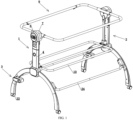
- a multifunctional crib includes a left support mechanism 1 and a right support mechanism 2 that are symmetrical to each other.
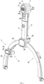
- Each of the left support mechanism 1 and the right support mechanism 2 includes a support base 3, a support tube 4, an inner sleeve 5, a left housing 6, a right housing 7 and a connecting rod 8.
- the support tube 4 is provided on a top portion of the support base 3.
- the inner sleeve 5 is provided in the support tube 4.
- the left housing 6 is provided on a top portion of the inner sleeve 5.
- the right housing 7 is provided at a right side of the left housing 6 and is connected to the left housing 6.
- the connecting rod 8 is provided beneath the right housing 7.
- the inner sleeve 5 is height-adjustable relative to the support tube 4.
- the left housing 6 and the right housing 7 are able to rock relative to each other.
- a portion of the support base 3 is retractable.
- An upper enclosure frame 9 is provided between the right housing 7 of the left support mechanism 1 and the right housing 7 of the right support mechanism 2.
- a support frame 10 is provided between a bottom portion of the connecting rod 8 of the left support mechanism 1 and a bottom portion of the connecting rod 8 of the right support mechanism 2.
- a lower portion of the left housing 6 communicates with the inner sleeve 5.
- a bottom portion of the inner sleeve 5 is provided with a lifting box 11.
- the lifting box 11 is internally provided with a lifting piece 12 and a clamping rod 13.
- the lifting piece 12 is configured to drive the clamping rod 13 to move left and right.
- the lower portion of the left housing 6 is provided with a pulling assembly 14.
- a pulling rope 15 is provided between the pulling assembly 14 and the lifting piece 12.
- a right side of the support tube 4 is provided with a plurality of clamping openings 41 arranged vertically. A right end of the clamping rod 13 passes through a right side of the lifting box 11 to be clamped into the clamping opening 41.
- the pulling assembly 14 includes a movable plate 141 and a first button 142.
- a pulling portion 143 is provided on a left side of the movable plate 141.
- the pulling portion 143 protrudes out of the open slot 61.
- the movable plate 141 is provided with a vertical slot 144 penetrating left and right, and the vertical slot 144 is located beneath the pulling portion 143.
- a right end of the first button 142 is provided with a blocking portion 145, and a left end surface of the blocking portion 145 is larger than a right end surface of the first button 142.
- a right end of the movable plate 141 is provided with a support step 146 for supporting a bottom surface of the blocking portion 145.
- An accommodating slot 63 is provided in a right inner end surface of the left housing 6.
- a left end of the first button 142 passes through the vertical slot 144 and the first button slot 62 in sequence, and a right end of the blocking portion 145 is located in the accommodating slot 63.
- the accommodating slot 63 is internally provided with a first spring 64 abutting against the right end of the blocking portion.
- a top portion of the lifting piece 12 is connected to the pulling rope 15, and a bottom portion of the lifting piece 12 is provided with a movement opening 121 extending upwardly.
- the movement opening 121 is internally provided with a movable piece 122.
- Two sides of the lifting piece 12 are respectively provided with inclined holes 123 communicating with the movement opening 121, and two sides of the movable piece 122 are respectively provided with clamping posts 124.
- Each of the clamping posts 124 is corresponding to and located in one inclined hole 123.
- the clamping rod 13 is connected to a right end of the movable piece 122.
- the lifting box 11 is internally provided with a second spring 110 abutting against a top portion of the lifting piece 12.
- a left inner surface of the lifting box 11 is provided with a limiting post 111.
- a left end of the movable piece 122 is provided with a limiting hole 125 adapted to the limiting post 111.
- the limiting post 111 is located in the limiting hole 125.
- the limiting hole 125 is internally provided with a third spring 126 abutting against the limiting post 111.
- the first button 142 is pressed to disengage the first button from the first button slot 62. Then, the pulling portion 143 is pulled upward, such that the movable plate 141 pulls the lifting piece 12 upward through the pulling rope 15. When the lifting piece 12 is raised, the clamping rod 13 moves to the left, such that the clamping rod 13 is disengaged from the matched clamping opening 41. At this time, the height of the inner sleeve 5 can be adjusted. After the adjustment of the height of the inner sleeve 5 is completed, the pulling portion 143 is released, such that the pulling portion 143 returns to the first button slot 62. The first button 142 is re-clamped, and the clamping rod 13 is re-clamped into a new clamping opening 41.
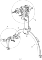
- a left end surface of the left housing 6 is provided with a second slot 65, and a left end surface of the right housing 7 is provided with a third slot 71.
- a right end of the left housing 6 is provided with two symmetrical rocking limiting slots 66, and the third slot 71 is internally provided with two symmetrical rocking limiting rods 72.
- Each of the rocking limiting rods 72 is corresponding to one rocking limiting slot 66, and each of left ends of the rocking limiting rods 72 is located in the corresponding rocking limiting slot 66.
- the second slot 65 is internally provided with a second movement slot 67, and the third slot 71 is internally provided with a third movement slot 73.
- the left end surface of the left housing 6 is covered with a first end cover 16 adapted to the second slot 65.
- a left end surface of the first end cover 16 is provided with a first sliding slot 161.
- the first sliding slot 161 is internally provided with a first sliding button 17 that is slidable left and right.
- the second movement slot 67 is internally provided with a first movable member 18, and the third movement slot 73 is internally provided with a second movable member 19.
- a plurality of first abutting posts 181 are evenly distributed at a right end surface of the first movable member 18, and the second movement slot 67 is internally provided with a plurality of post slots 68 into which the plurality of first abutting posts 181 extend.
- a plurality of second abutting posts 191 are evenly distributed at a left end surface of the second movable member 19.
- Each of the plurality of second abutting posts 191 is corresponding to one first abutting post 181 and one post slot 68, and left ends of the plurality of second abutting posts 191 protrude into the corresponding post slots 68 to abut against the first abutting posts 181.
- the third movement slot 73 is internally provided with a fourth spring 74 abutting against a right end surface of the second movable member 19.
- the first sliding button 17 is connected to the first movable member 18, and the first sliding button 17 is able to be fixed to the first end cover 16 after sliding.
- the second slot 65 is internally provided with two symmetrical first connecting posts 651, two symmetrical notches 652 and two symmetrical clamping plates 653.
- Each of the first connecting posts 651 is corresponding to one notch 652 and one clamping plate 653, and each of the clamping plates 653 is located between the corresponding first connecting post 651 and notch 652.
- the third slot 71 is internally provided with two symmetrical second connecting posts 75, and each of the second connecting posts 75 is corresponding to one notch 652.
- the second slot 65 is internally provided with two symmetrical centering springs 69.
- Each of the centering springs 69 is corresponding to one first connecting post 651, one clamping plate 653, one notch 652 and one second connecting post 75.
- the centering springs 69 is provided with one end connected to the first connecting post 651, a central portion clamped to the clamping plate 653, and the other end passing through the notch 652 and connected to the second connecting post 75.
- a right end surface of the first sliding button 17 is provided with a driving portion 171.
- the driving portion 171 is provided with a through slot 172 penetrating vertically.
- An unlocking button 173 passes through the first sliding button 17.
- a left end of the unlocking button 17 protrudes out of the first sliding button 17, and the other end of the unlocking button 17 is located in the through slot 172 and provided with a vertical plate 174.
- Top and bottom surfaces of the vertical plate 174 are respectively provided with first clamping portions 175.
- the through slot 172 is internally provided with a fifth spring 170 abutting against the vertical plate 174.
- a right end surface of the driving portion 171 defines a first inclined surface 176.
- a left end surface of the first movable member 18 is provided with a fourth movement slot 182.
- An end surface of the fourth movement slot 182 defines a second inclined surface 183 attached to the first inclined surface 176.
- a right end of the driving portion 171 is located in the fourth movement slot 182.
- a front end of the second inclined surface 183 is provided with a limiting portion 184.
- a right end surface of the first end cover 16 is provided with two abutting portions 162 arranged vertically. The two abutting portions 162 are corresponding to the first clamping portions 175 on the top and bottom surfaces of the vertical plate 174, respectively, and each of the first clamping portions 175 abuts against two sides of each of the corresponding abutting portions 162.
- the unlocking button 173 is pressed such that the first clamping portions 175 are disengaged from the abutting portions 162. Then, the first sliding button 17 is slid forward.
- the first inclined surface 176 cooperates with the second inclined surface 183, such that when the first sliding button 17 is slid forward, the first movable member 18 moves to the right, and the first abutting posts 181 of the first movable member 18 always abut against the second abutting posts 191.
- the unlocking button 173 is released, such that the first clamping portions 175 abut against the abutting portions 162, thereby fixing the first sliding button 17.
- the left housing 6 and the right housing 7 can be rocked relative to each other.
- the two centering springs 69 make the right housing 7 center quickly and automatically when no external rocking force is applied.
- the unlocking button 173 is pressed, such that the first clamping portions 175 are disengaged from the abutting portions 162. Then, the first sliding button 17 is slid rearward to make the first sliding button 17, the first movable member 18 and the second movable member 19 return to their original positions.
- the unlocking button 173 is released, such that the first clamping portions 175 abut against the abutting portions 162. At this time, the left housing 6 and the right housing 7 can be relatively fixed.
- the support base 3 includes a front arc rod 31, a rear arc rod 32 and a connecting piece 33.
- the connecting piece 33 is provided between a top end of the front arc rod 31 and a top end of the rear arc rod 32.
- a bottom portion of the support tube 4 is connected to the connecting piece 33.
- the front arc rod 31 includes an upper arc rod 34 and a lower arc rod 35.
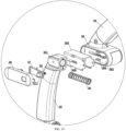
- a bottom end of the upper arc rod 34 is provided with a lower housing 36.
- the lower housing 36 is internally provided with a second sliding slot 361 with a bottom opening.
- a left end surface of the lower housing 36 is provided with a cover slot 362.
- the cover slot 362 is internally provided with a second button 37.
- the cover slot 362 is covered with a second end cover 38 adapted to the cover slot.
- the cover slot 362 is provided with an upper hinge portion 363 and a lower hinge portion 364.
- the second button 37 is located between the upper hinge portion 363 and the lower hinge portion 364.
- a middle portion of the second button 37 is hinged to the upper hinge portion 363 and the lower hinge portion 364.
- a rear portion of a left end surface of the second button 37 is provided with a pressing portion 371, and the pressing portion 371 passes through a left end surface of the second end cover 38.
- a sixth spring 39 is provided between a rear portion of a right end surface of the second button 37 and the cover slot 362.
- the lower housing 36 is internally provided with an angle iron piece 365, and the angle iron piece 365 is in an inverted U shape.
- a sliding portion 351 is provided on a top portion of the lower arc rod 35.
- the sliding portion 351 is located in the angle iron piece 365.
- the sliding portion 351 is connected to the angle iron piece 365 by a rivet (not shown in the figure).
- the rivet (not shown in the figure) passes through the sliding portion 351 and the strip slots 366 on the left and right sides of the angle iron piece 365.
- a left end of the rivet (not shown in the figure) is able to abut against a front end of the second button 37.
- the second sliding slot 361 is internally provided with a seventh spring 30 abutting against the sliding portion 351.
- the upper enclosure frame 9 includes a U-shaped tube 91, a left connecting tube 92, a right connecting tube 93 and a detachable tube 94.
- Two ends of the U-shaped tube 91 respectively pass through the right housing 7 of the left support mechanism 1 and the right housing 7 of the right support mechanism 2 to be respectively connected to the left connecting tube 92 and the right connecting tube 93.
- the detachable tube 94 is detachably provided between the left connecting tube 92 and the right connecting tube 93.
- Each of two ends of the detachable tube 94 is internally provided with a third movable member 95 and an eighth spring (not shown in the figure).
- the third movable member 95 has a bottom portion provided with a push portion 951, one end surface provided with an insertion rod 952, and the other end surface abutting against the eighth spring (not shown in the figure).
- An end surface of each of the left connecting tube 92 and the right connecting tube 93 is provided with an insertion slot 96 for the insertion of the insertion rod.
- An end portion of each of the left connecting tube 92 and the right connecting tube 93 is provided with a positioning portion 97.
- Each of two ends of the detachable tube 94 is provided with a positioning slot 98 adapted to the positioning portion 97.
- the detachable tube 94 can be detached from the left connecting tube 92 and the right connecting tube 93. To do so, first, the push portions 951 are pushed to disengage the insertion rods 952 from the insertion slots 96. Then, the detachable tube 94 is raised such that the positioning portions 97 are disengaged from the positioning slots 98.
- the bottom portion of the connecting rod 8 of the left support mechanism 1 and the bottom portion of the connecting rod 8 of the right support mechanism 2 are respectively provided with clamping members 23.
- the support frame 10 is provided between the clamping member 23 of the left support mechanism 1 and the clamping member 23 of the right support mechanism 2.
- Reinforcing rods 24 are provided between the support base 3 of the left support mechanism 1 and the support base 3 of the right support mechanism 2.
Landscapes
- Purses, Travelling Bags, Baskets, Or Suitcases (AREA)
- Carriages For Children, Sleds, And Other Hand-Operated Vehicles (AREA)
Claims (9)
- Multifunktionales Kinderbett, umfassend einen linken Stützmechanismus (1) und einen rechten Stützmechanismus (2), wobei der linke Stützmechanismus (1) und der rechte Stützmechanismus (2) symmetrisch zueinander sind, wobei der linke Stützmechanismus (1) und der rechte Stützmechanismus (2) jeweils eine Stützbasis (3), ein Stützrohr (4), eine Innenhülse (5), ein linkes Gehäuse (6), ein rechtes Gehäuse (7) und eine Verbindungsstange (8) umfassen; das Stützrohr (4) an einem oberen Abschnitt der Stützbasis (3) bereitgestellt ist; die Innenhülse (5) in dem Stützrohr (4) bereitgestellt ist; das linke Gehäuse (6) an einem oberen Abschnitt der Innenhülse (5) bereitgestellt ist; das rechte Gehäuse (7) an einer rechten Seite des linken Gehäuses (6) bereitgestellt ist; die Verbindungsstange (8) unter dem rechten Gehäuse (7) bereitgestellt ist; die Innenhülse (5) relativ zu dem Stützrohr (4) höhenverstellbar ist; das linke Gehäuse (6) und das rechte Gehäuse (7) dazu eingerichtet sind, relativ zueinander zu schaukeln; ein Abschnitt der Stützbasis (3) einziehbar ist; zwischen dem rechten Gehäuse (7) des linken Stützmechanismus (1) und dem rechten Gehäuse (7) des rechten Stützmechanismus (2) ein oberer Einfassungsrahmen (9) bereitgestellt ist; und zwischen einem unteren Abschnitt der Verbindungsstange (8) des linken Stützmechanismus (1) und einem unteren Abschnitt der Verbindungsstange (8) des rechten Stützmechanismus (2) ein Stützrahmen (10) bereitgestellt ist, wobei eine linke Stirnfläche des linken Gehäuses (6) mit einem zweiten Schlitz (65) versehen ist und eine linke Stirnfläche des rechten Gehäuses (7) mit einem dritten Schlitz (71) versehen ist; ein rechtes Ende des linken Gehäuses (6) mit zwei symmetrischen Schaukelbegrenzungsschlitzen (66) versehen ist und der dritte Schlitz (71) innen mit zwei symmetrischen Schaukelbegrenzungsstangen (72) versehen ist; eine jeweilige der beiden symmetrischen Schaukelbegrenzungsstangen (72) einer jeweiligen der zwei symmetrischen Schaukelbegrenzungsschlitze (66) entspricht und ein jeweiliges linkes Ende der beiden symmetrischen Schaukelbegrenzungsstangen (72) in einem jeweiligen der beiden symmetrischen Schaukelbegrenzungsschlitze (66) angeordnet ist; der zweite Schlitz (65) innen mit einem zweiten Bewegungsschlitz (67) versehen ist und der dritte Schlitz (71) innen mit einem dritten Bewegungsschlitz (73) versehen ist; die linke Stirnfläche des linken Gehäuses (6) mit einer ersten Endabdeckung (16) abgedeckt ist, die an den zweiten Schlitz (65) angepasst ist; eine linke Stirnfläche der ersten Endabdeckung (16) mit einem ersten Gleitschlitz (161) versehen ist; der erste Gleitschlitz (161) innen mit einem ersten Gleitknopf (17) versehen ist, wobei der erste Gleitknopf (17) nach links und rechts verschiebbar ist; der zweite Bewegungsschlitz (67) innen mit einem ersten beweglichen Element (18) versehen ist und der dritte Bewegungsschlitz (73) innen mit einem zweiten beweglichen Element (19) versehen ist; an einer rechten Stirnfläche des ersten beweglichen Elements (18) gleichmäßig mehrere erste Anschlagzapfen (181) verteilt sind und der zweite Bewegungsschlitz (67) innen mit mehreren Zapfenschlitzen (68) versehen ist, wobei sich die mehreren ersten Anschlagzapfen (181) jeweils in die mehreren Zapfenschlitze (68) hinein erstrecken; an einer linken Stirnfläche des zweiten beweglichen Elements (19) gleichmäßig mehrere zweite Anschlagzapfen (191) verteilt sind; jeder der mehreren zweiten Anschlagzapfen (191) jeweils einem der mehreren ersten Anschlagzapfen (181) und jeweils einem der mehreren Zapfenschlitze (68) entspricht und jeweils ein linkes Ende des zweiten Anschlagzapfens (191) in den Zapfenschlitz (68) hineinragt, um an dem Anschlagzapfen (181) anzuschlagen; der dritte Bewegungsschlitz (73) innen mit einer vierten Feder (74) versehen ist, die an einer rechten Stirnfläche des zweiten beweglichen Elements (19) anliegt; und der erste Gleitknopf (17) mit dem ersten beweglichen Element (18) verbunden ist und der erste Gleitknopf (17) dazu eingerichtet ist, nach dem Gleiten an der ersten Endabdeckung (16) fixiert zu werden;
dadurch gekennzeichnet, dass eine rechte Stirnfläche des ersten Gleitknopfs (17) mit einem Antriebsabschnitt (171) versehen ist; der Antriebsabschnitt (171) mit einem Durchgangsschlitz (172) versehen ist, der diesen vertikal durchdringt, ein Entriegelungsknopf (173) durch den ersten Gleitknopf (17) verläuft; ein linkes Ende des Entriegelungsknopfs (173) aus dem ersten Gleitknopf (17) herausragt und ein rechtes Ende des Entriegelungsknopfs (173) in dem Durchgangsschlitz (172) angeordnet und mit einer vertikalen Platte (174) versehen ist; eine obere und eine untere Fläche der vertikalen Platte (174) jeweils mit einem ersten Klemmabschnitt (175) versehen ist; der Durchgangsschlitz (172) innen mit einer fünften Feder (170) versehen ist, die an der vertikalen Platte (174) anliegt; eine rechte Stirnfläche des Antriebsabschnitts (171) eine erste schräge Fläche (176) definiert, eine linke Stirnfläche des ersten beweglichen Elements (18) mit einem vierten Bewegungsschlitz (182) versehen ist; eine Stirnfläche des vierten Bewegungsschlitzes (182) eine zweite schräge Fläche (183) definiert, die an der ersten schrägen Fläche (176) befestigt ist; ein rechtes Ende des Antriebsabschnitts (171) in dem vierten Bewegungsschlitz (182) angeordnet ist; ein vorderes Ende der zweiten schrägen Fläche (183) mit einem Begrenzungsabschnitt (184) versehen ist; eine rechte Stirnfläche der ersten Endabdeckung (16) mit zwei Anschlagabschnitten (162) versehen ist, die vertikal angeordnet sind; die beiden Anschlagabschnitte (162) den jeweiligen ersten Klemmabschnitten (175) an der oberen und der unteren Fläche der vertikalen Platte (174) entsprechen; und jeder der ersten Klemmabschnitte (175) jeweils an zwei Seiten eines der Anschlagabschnitte (162) anliegt. - Multifunktionales Kinderbett nach Anspruch 1, wobei ein unterer Abschnitt des linken Gehäuses (6) mit der Innenhülse (5) in Verbindung steht; ein unterer Abschnitt der Innenhülse (5) mit einem Hebekasten (11) versehen ist; der Hebekasten (11) innen mit einem Hebestück (12) und einer Klemmstange (13) versehen ist; das Hebestück (12) dazu eingerichtet ist, die Klemmstange (13) dazu anzutreiben, sich nach links und rechts zu bewegen; der untere Abschnitt des linken Gehäuses (6) mit einer Zuganordnung (14) versehen ist; zwischen der Zuganordnung (14) und dem Hebestück (12) ein Zugseil (15) bereitgestellt ist; eine rechte Seite des Stützrohrs (4) mit mehreren Klemmöffnungen (41) versehen ist, die vertikal angeordnet sind; und ein rechtes Ende der Klemmstange (13) durch eine rechte Seite des Hebekastens (11) verläuft, um in eine Klemmöffnung (41) der mehreren Klemmöffnungen (41) geklemmt zu werden.
- Multifunktionales Kinderbett nach Anspruch 2, wobei der untere Abschnitt des linken Gehäuses (6) mit einem offenen Schlitz (61) und einem ersten Knopfschlitz (62) versehen ist; die Zuganordnung (14) eine bewegliche Platte (141) und einen ersten Knopf (142) umfasst; an einer linken Seite der beweglichen Platte (141) ein Zugabschnitt (143) bereitgestellt ist; der Zugabschnitt (143) aus dem offenen Schlitz (61) herausragt; die bewegliche Platte (141) mit einem vertikalen Schlitz (144) versehen ist, der diese links und rechts durchdringt, und der vertikale Schlitz (144) unter dem Zugabschnitt (143) angeordnet ist; ein rechtes Ende des ersten Knopfs (142) mit einem Blockierabschnitt (145) versehen ist und eine linke Stirnfläche des Blockierabschnitts (145) größer als eine rechte Stirnfläche des ersten Knopfs (142) ist; ein rechtes Ende der beweglichen Platte (141) mit einer Stützstufe (146) zum Stützen einer unteren Fläche des Blockierabschnitts (145) versehen ist; in einer rechten inneren Stirnfläche des linken Gehäuses (6) ein Aufnahmeschlitz (63) bereitgestellt ist; ein linkes Ende des ersten Knopfs (142) nacheinander durch den vertikalen Schlitz (144) und den ersten Knopfschlitz (62) verläuft; ein rechtes Ende des Blockierabschnitts (145) in dem Aufnahmeschlitz (63) angeordnet ist; und der Aufnahmeschlitz (63) innen mit einer ersten Feder (64) versehen ist, die an dem rechten Ende des Blockierabschnitts (145) anliegt.
- Multifunktionales Kinderbett nach Anspruch 2, wobei ein oberer Abschnitt des Hebestücks (12) mit dem Zugseil (15) verbunden ist und ein unterer Abschnitt des Hebestücks (12) mit einer sich nach oben erstreckenden Bewegungsöffnung (121) versehen ist; die Bewegungsöffnung (121) innen mit einem beweglichen Stück (122) versehen ist; zwei Seiten des Hebestücks (12) jeweils mit einem schrägen Loch (123) versehen sind, das mit der Bewegungsöffnung (121) in Verbindung steht, und zwei Seiten des beweglichen Stücks (122) jeweils mit einem Klemmzapfen (124) versehen sind; der jeweilige Klemmzapfen (124) dem jeweiligen schrägen Loch (123) entspricht und in diesen angeordnet ist; die Klemmstange (13) mit einem rechten Ende des beweglichen Stücks (122) verbunden ist; der Hebekasten (11) innen mit einer zweiten Feder (110) versehen ist, die an einem oberen Abschnitt des Hebestücks (12) anliegt; eine linke Innenfläche des Hebekastens (11) mit einem Begrenzungszapfen (111) versehen ist; ein linkes Ende des beweglichen Stücks (122) mit einem Begrenzungsloch (125) versehen ist, das an den Begrenzungszapfen (111) angepasst ist; der Begrenzungszapfen (111) in dem Begrenzungsloch (125) angeordnet ist; und das Begrenzungsloch (125) innen mit einer dritten Feder (126) versehen ist, die an dem Begrenzungszapfen (111) anliegt.
- Multifunktionales Kinderbett nach Anspruch 1, wobei der zweite Schlitz (65) innen mit zwei symmetrischen ersten Verbindungszapfen (651), zwei symmetrischen Einkerbungen (652) und zwei symmetrischen Klemmplatten (653) versehen ist; ein jeweiliger erster Verbindungszapfen (651) der beiden symmetrischen ersten Verbindungszapfen (651) einer jeweiligen Einkerbung (652) der beiden symmetrischen Einkerbungen (652) und einer jeweiligen Klemmplatte (653) der beiden symmetrischen Klemmplatten (653) entspricht und eine jeweilige Klemmplatte (653) zwischen einem jeweiligen ersten Verbindungszapfen (651) und einer jeweiligen Einkerbung (652) angeordnet ist; der dritte Schlitz (71) innen mit zwei symmetrischen zweiten Verbindungszapfen (75) versehen ist und ein jeweiliger zweiter Verbindungszapfen (75) der beiden symmetrischen zweiten Verbindungszapfen (75) einer jeweiligen Einkerbung (652) entspricht; der zweite Schlitz (65) innen mit zwei symmetrischen Zentrierfedern (69) versehen ist; eine jeweilige Zentrierfeder (69) der beiden symmetrischen Zentrierfedem (69) einem jeweiligen ersten Verbindungszapfen (651), einer jeweiligen Klemmplatte (653), einer jeweiligen Einkerbung (652) und einem jeweiligen zweiten Verbindungszapfen (75) entspricht; und eine jeweilige Zentrierfeder (69) mit einem ersten Ende, das mit einem jeweiligen ersten Verbindungszapfen (651) verbunden ist, einem Mittelabschnitt, der an einer jeweiligen Klemmplatte (653) festgeklemmt ist, und einem zweiten Ende versehen ist, das durch eine jeweilige Einkerbung (652) verläuft und mit einem jeweiligen zweiten Verbindungszapfen (75) verbunden ist.
- Multifunktionales Kinderbett nach Anspruch 1, wobei die Stützbasis (3) eine vordere Bogenstange (31), eine hintere Bogenstange (32) und ein Verbindungsstück (33) umfasst; das Verbindungsstück (33) zwischen einem oberen Ende der vorderen Bogenstange (31) und einem oberen Ende der hinteren Bogenstange (32) bereitgestellt ist; ein unterer Abschnitt des Stützrohrs (4) mit dem Verbindungsstück (33) verbunden ist; die vordere Bogenstange (31) eine obere Bogenstange (34) und eine untere Bogenstange (35) umfasst; ein unteres Ende der oberen Bogenstange (34) mit einem unteren Gehäuse (36) versehen ist; das untere Gehäuse (36) innen mit einem zweiten Gleitschlitz (361) mit einer unteren Öffnung versehen ist; eine linke Stirnfläche des unteren Gehäuses (36) mit einem Abdeckungsschlitz (362) versehen ist; der Abdeckungsschlitz (362) innen mit einem zweiten Knopf (37) versehen ist; der Abdeckungsschlitz (362) mit einer zweiten Endabdeckung (38) abgedeckt ist, die an den Abdeckungsschlitz (362) angepasst ist; der Abdeckungsschlitz (362) mit einem oberen Scharnierabschnitt (363) und einem unteren Scharnierabschnitt (364) versehen ist; der zweite Knopf (37) zwischen dem oberen Scharnierabschnitt (363) und dem unteren Scharnierabschnitt (364) angeordnet ist; ein mittlerer Abschnitt des zweiten Knopfs (37) an den oberen Scharnierabschnitt (363) und den unteren Scharnierabschnitt (364) angelenkt ist; ein hinterer Abschnitt einer linken Stirnfläche des zweiten Knopfs (37) mit einem Druckabschnitt (371) versehen ist und der Druckabschnitt (371) durch eine linke Stirnfläche der zweiten Endabdeckung (38) verläuft; zwischen einem hinteren Abschnitt einer rechten Stirnfläche des zweiten Knopfs (37) und dem Abdeckungsschlitz (362) eine sechste Feder (39) bereitgestellt ist; das untere Gehäuse (36) innen mit einem Winkeleisenstück (365) versehen ist und das Winkeleisenstück (365) eine umgekehrte u-Form aufweist; eine linke und eine rechte Seite des Winkeleisenstücks (365) jeweils mit einem Streifenschlitz (366) versehen sind; an einem oberen Abschnitt der unteren Bogenstange (35) ein Gleitabschnitt (351) bereitgestellt ist; der Gleitabschnitt (351) in dem Winkeleisenstück (365) angeordnet ist und der Gleitabschnitt (351) mit dem Winkeleisenstück (365) durch ein Niet verbunden ist; das Niet durch den Gleitabschnitt (351) und die Streifenschlitze (366) auf der linken und der rechten Seite des Winkeleisenstücks (365) verläuft; ein linkes Ende des Niets dazu eingerichtet ist, an einem vorderen Ende des zweiten Knopfs (37) anzuliegen; und der zweite Gleitschlitz (361) innen mit einer siebten Feder (30) versehen ist, die an dem Gleitabschnitt (351) anliegt.
- Multifunktionales Kinderbett nach Anspruch 1, wobei der obere Einfassungsrahmen (9) ein u-förmiges Rohr (91), ein linkes Verbindungsrohr (92), ein rechtes Verbindungsrohr (93) und ein abnehmbares Rohr (94) umfasst; zwei Enden des u-förmigen Rohrs (91) jeweils durch das rechte Gehäuse (7) des linken Stützmechanismus (1) und das rechte Gehäuse (7) des rechten Stützmechanismus (2) verlaufen, um jeweils mit dem linken Verbindungsrohr (92) und dem rechten Verbindungsrohr (93) verbunden zu sein; und das abnehmbare Rohr (94) abnehmbar zwischen dem linken Verbindungsrohr (92) und dem rechten Verbindungsrohr (93) bereitgestellt ist.
- Multifunktionales Kinderbett nach Anspruch 7, wobei jedes von zwei Enden des abnehmbaren Rohrs (94) innen mit einem dritten beweglichen Element (95) und einer achten Feder versehen ist; das dritte bewegliche Element (95) einen unteren Abschnitt, der mit einem Schiebeabschnitt (951) versehen ist, eine erste Stirnfläche, die mit einer Einführstange (952) versehen ist, und eine zweite Stirnfläche aufweist, die an der achten Feder anliegt; eine jeweilige Stirnfläche des linken Verbindungsrohrs (92) und des rechten Verbindungsrohrs (93) jeweils mit einem Einführschlitz (96) für ein Einführen der Einführstange (952) versehen ist; ein jeweiliger Endabschnitt des linken Verbindungsrohrs (92) und des rechten Verbindungsrohrs (93) jeweils mit einem Positionierungsabschnitt (97) versehen ist; und beide Enden des abnehmbaren Rohrs (94) jeweils mit einem Positionierungsschlitz (98) versehen sind, der an den Positionierungsabschnitt (97) angepasst ist.
- Multifunktionales Kinderbett nach Anspruch 1, wobei der untere Abschnitt der Verbindungsstange (8) des linken Stützmechanismus (1) mit einem ersten Klemmelement (23) versehen ist und der untere Abschnitt der Verbindungsstange (8) des rechten Stützmechanismus (2) mit einem zweiten Klemmelement (23) versehen ist; und der Stützrahmen (10) zwischen dem ersten Klemmelement (23) des linken Stützmechanismus (1) und dem zweiten Klemmelement (23) des rechten Stützmechanismus (2) bereitgestellt ist.
Applications Claiming Priority (1)
| Application Number | Priority Date | Filing Date | Title |
|---|---|---|---|
| CN202123356255.6U CN217185436U (zh) | 2021-12-29 | 2021-12-29 | 一种使用功能丰富的婴儿睡床 |
Publications (2)
| Publication Number | Publication Date |
|---|---|
| EP4205604A1 EP4205604A1 (de) | 2023-07-05 |
| EP4205604B1 true EP4205604B1 (de) | 2024-04-10 |
Family
ID=82492825
Family Applications (1)
| Application Number | Title | Priority Date | Filing Date |
|---|---|---|---|
| EP22182355.2A Active EP4205604B1 (de) | 2021-12-29 | 2022-06-30 | Multifunktionskrippe |
Country Status (3)
| Country | Link |
|---|---|
| US (1) | US12453430B2 (de) |
| EP (1) | EP4205604B1 (de) |
| CN (1) | CN217185436U (de) |
Cited By (1)
| Publication number | Priority date | Publication date | Assignee | Title |
|---|---|---|---|---|
| US12357107B2 (en) * | 2022-04-28 | 2025-07-15 | TJ(fujian) Industrial Co., Ltd. | Crib |
Families Citing this family (7)
| Publication number | Priority date | Publication date | Assignee | Title |
|---|---|---|---|---|
| USD1011068S1 (en) * | 2021-12-29 | 2024-01-16 | TJ(fujian) Industrial Co., Ltd. | Bassinet |
| USD1011066S1 (en) * | 2022-04-13 | 2024-01-16 | Dezhu Ou | Baby bed |
| CN217644908U (zh) * | 2022-04-21 | 2022-10-25 | 中山优优贝日用制品有限公司 | 一种摇床 |
| USD1011067S1 (en) * | 2022-05-18 | 2024-01-16 | Dezhu Ou | Baby bed |
| CN219125832U (zh) * | 2023-02-17 | 2023-06-06 | 广州麦锶顿日用品有限公司 | 一种婴儿摇床 |
| CN220069303U (zh) * | 2023-04-07 | 2023-11-24 | 厦门梦贝比儿童用品有限公司 | 一种多用途儿童餐椅 |
| USD1002222S1 (en) * | 2023-05-12 | 2023-10-24 | Liqun JIANG | Foldable bracket |
Family Cites Families (15)
| Publication number | Priority date | Publication date | Assignee | Title |
|---|---|---|---|---|
| US744993A (en) * | 1903-08-22 | 1903-11-24 | John Barta | Cradle. |
| US7788744B2 (en) * | 2007-02-15 | 2010-09-07 | Kolcraft Enterprises, Inc. | Self rocking sleeping compartment assemblies and method of driving the same |
| US9565950B2 (en) * | 2013-12-20 | 2017-02-14 | Wonderland Nurserygoods Company, Ltd. | Infant care apparatus |
| US9888786B2 (en) * | 2014-05-29 | 2018-02-13 | Kids Ii, Inc. | Child sleeping apparatus |
| US10383455B2 (en) * | 2015-03-30 | 2019-08-20 | Kids Ii, Inc. | Depth-adjustable bassinet |
| US9642473B2 (en) * | 2015-09-08 | 2017-05-09 | Way-Hong Chen | Baby rocking bed with multiple functions |
| CN207370408U (zh) * | 2017-01-06 | 2018-05-18 | 厦门梦贝比儿童用品有限公司 | 一种婴儿床 |
| IT201700008130A1 (it) * | 2017-01-25 | 2018-07-25 | Artsana Spa | Culla |
| CN211092967U (zh) * | 2019-10-19 | 2020-07-28 | 中山市童博适日用制品有限公司 | 一种婴儿摇篮床 |
| CN212546368U (zh) * | 2020-01-15 | 2021-02-19 | 中童(厦门)婴童智能家居有限公司 | 一种多功能小睡床 |
| CN113142899A (zh) * | 2021-03-26 | 2021-07-23 | 浙江群英车业有限公司 | 一种可转变为床边床的婴儿床 |
| CN215015559U (zh) * | 2021-04-18 | 2021-12-07 | 厦门梦贝比儿童用品有限公司 | 一种功能多样的小睡床 |
| CN215738057U (zh) * | 2021-04-18 | 2022-02-08 | 厦门梦贝比儿童用品有限公司 | 一种安全性能高的小睡床 |
| USD1011070S1 (en) * | 2021-12-29 | 2024-01-16 | TJ(fujian) Industrial Co., Ltd. | Bassinet |
| USD1011069S1 (en) * | 2022-04-06 | 2024-01-16 | Dezhu Ou | Baby bed |
-
2021
- 2021-12-29 CN CN202123356255.6U patent/CN217185436U/zh active Active
-
2022
- 2022-06-30 EP EP22182355.2A patent/EP4205604B1/de active Active
- 2022-12-29 US US18/090,554 patent/US12453430B2/en active Active
Cited By (1)
| Publication number | Priority date | Publication date | Assignee | Title |
|---|---|---|---|---|
| US12357107B2 (en) * | 2022-04-28 | 2025-07-15 | TJ(fujian) Industrial Co., Ltd. | Crib |
Also Published As
| Publication number | Publication date |
|---|---|
| US20230200559A1 (en) | 2023-06-29 |
| CN217185436U (zh) | 2022-08-16 |
| EP4205604A1 (de) | 2023-07-05 |
| US12453430B2 (en) | 2025-10-28 |
Similar Documents
| Publication | Publication Date | Title |
|---|---|---|
| US12453430B2 (en) | Multifunctional crib | |
| US12446708B2 (en) | Crib | |
| KR101834474B1 (ko) | 사용 편의성을 향상시킨 유아용 웨건 | |
| EP4268677B1 (de) | Kinderbett | |
| CA2406886C (en) | Multi-level multiple purpose convertible playpen | |
| US11730284B2 (en) | Multipurpose bassinet | |
| JPH0336311Y2 (de) | ||
| AU2026200434A1 (en) | Handle adjustment mechanism and child crib therewith | |
| US11350765B2 (en) | Multi-functional baby bed | |
| US12274378B2 (en) | Bassinet | |
| TWI809688B (zh) | 支架連接結構、支座、嬰兒床及其床體 | |
| CA2468572A1 (en) | Bassinet selectively rockable when mounted upon a support as well as being displaced therefrom | |
| EP4029411B1 (de) | Kinderliege | |
| CN211092967U (zh) | 一种婴儿摇篮床 | |
| US5890263A (en) | Split lockable hinge for a baby bed | |
| CN212939056U (zh) | 一种高度可调的婴儿床 | |
| CN212546366U (zh) | 一种可升降的婴儿睡床架 | |
| EP4098153B1 (de) | Faltbarer kleiner esszimmerstuhl | |
| US6571408B1 (en) | Oscillatory device for a collapsible playpen | |
| CN217623725U (zh) | 一种可拆卸的儿童推车座椅 | |
| US20020197101A1 (en) | Position adjusting means for a back of a stroller | |
| CN222917238U (zh) | 一种婴儿摇床 | |
| CN222804116U (zh) | 一种婴儿床架 | |
| CN210581842U (zh) | 一种婴儿床架 | |
| CN114919475A (zh) | 一种儿童安全座椅的一键解锁旋转调节结构 |
Legal Events
| Date | Code | Title | Description |
|---|---|---|---|
| PUAI | Public reference made under article 153(3) epc to a published international application that has entered the european phase |
Free format text: ORIGINAL CODE: 0009012 |
|
| STAA | Information on the status of an ep patent application or granted ep patent |
Free format text: STATUS: REQUEST FOR EXAMINATION WAS MADE |
|
| 17P | Request for examination filed |
Effective date: 20220630 |
|
| AK | Designated contracting states |
Kind code of ref document: A1 Designated state(s): AL AT BE BG CH CY CZ DE DK EE ES FI FR GB GR HR HU IE IS IT LI LT LU LV MC MK MT NL NO PL PT RO RS SE SI SK SM TR |
|
| GRAP | Despatch of communication of intention to grant a patent |
Free format text: ORIGINAL CODE: EPIDOSNIGR1 |
|
| RIC1 | Information provided on ipc code assigned before grant |
Ipc: A47D 9/02 20060101ALI20231002BHEP Ipc: A47D 9/00 20060101ALI20231002BHEP Ipc: A47D 7/02 20060101AFI20231002BHEP |
|
| STAA | Information on the status of an ep patent application or granted ep patent |
Free format text: STATUS: GRANT OF PATENT IS INTENDED |
|
| INTG | Intention to grant announced |
Effective date: 20231109 |
|
| GRAS | Grant fee paid |
Free format text: ORIGINAL CODE: EPIDOSNIGR3 |
|
| GRAA | (expected) grant |
Free format text: ORIGINAL CODE: 0009210 |
|
| STAA | Information on the status of an ep patent application or granted ep patent |
Free format text: STATUS: THE PATENT HAS BEEN GRANTED |
|
| AK | Designated contracting states |
Kind code of ref document: B1 Designated state(s): AL AT BE BG CH CY CZ DE DK EE ES FI FR GB GR HR HU IE IS IT LI LT LU LV MC MK MT NL NO PL PT RO RS SE SI SK SM TR |
|
| REG | Reference to a national code |
Ref country code: GB Ref legal event code: FG4D |
|
| REG | Reference to a national code |
Ref country code: CH Ref legal event code: EP |
|
| REG | Reference to a national code |
Ref country code: DE Ref legal event code: R096 Ref document number: 602022002792 Country of ref document: DE |
|
| REG | Reference to a national code |
Ref country code: IE Ref legal event code: FG4D |
|
| REG | Reference to a national code |
Ref country code: LT Ref legal event code: MG9D |
|
| REG | Reference to a national code |
Ref country code: NL Ref legal event code: MP Effective date: 20240410 |
|
| REG | Reference to a national code |
Ref country code: AT Ref legal event code: MK05 Ref document number: 1673970 Country of ref document: AT Kind code of ref document: T Effective date: 20240410 |
|
| PG25 | Lapsed in a contracting state [announced via postgrant information from national office to epo] |
Ref country code: NL Free format text: LAPSE BECAUSE OF FAILURE TO SUBMIT A TRANSLATION OF THE DESCRIPTION OR TO PAY THE FEE WITHIN THE PRESCRIBED TIME-LIMIT Effective date: 20240410 |
|
| PG25 | Lapsed in a contracting state [announced via postgrant information from national office to epo] |
Ref country code: NL Free format text: LAPSE BECAUSE OF FAILURE TO SUBMIT A TRANSLATION OF THE DESCRIPTION OR TO PAY THE FEE WITHIN THE PRESCRIBED TIME-LIMIT Effective date: 20240410 |
|
| PG25 | Lapsed in a contracting state [announced via postgrant information from national office to epo] |
Ref country code: IS Free format text: LAPSE BECAUSE OF FAILURE TO SUBMIT A TRANSLATION OF THE DESCRIPTION OR TO PAY THE FEE WITHIN THE PRESCRIBED TIME-LIMIT Effective date: 20240810 |
|
| PG25 | Lapsed in a contracting state [announced via postgrant information from national office to epo] |
Ref country code: BG Free format text: LAPSE BECAUSE OF FAILURE TO SUBMIT A TRANSLATION OF THE DESCRIPTION OR TO PAY THE FEE WITHIN THE PRESCRIBED TIME-LIMIT Effective date: 20240410 |
|
| PG25 | Lapsed in a contracting state [announced via postgrant information from national office to epo] |
Ref country code: FI Free format text: LAPSE BECAUSE OF FAILURE TO SUBMIT A TRANSLATION OF THE DESCRIPTION OR TO PAY THE FEE WITHIN THE PRESCRIBED TIME-LIMIT Effective date: 20240410 Ref country code: HR Free format text: LAPSE BECAUSE OF FAILURE TO SUBMIT A TRANSLATION OF THE DESCRIPTION OR TO PAY THE FEE WITHIN THE PRESCRIBED TIME-LIMIT Effective date: 20240410 |
|
| PG25 | Lapsed in a contracting state [announced via postgrant information from national office to epo] |
Ref country code: GR Free format text: LAPSE BECAUSE OF FAILURE TO SUBMIT A TRANSLATION OF THE DESCRIPTION OR TO PAY THE FEE WITHIN THE PRESCRIBED TIME-LIMIT Effective date: 20240711 |
|
| PG25 | Lapsed in a contracting state [announced via postgrant information from national office to epo] |
Ref country code: PT Free format text: LAPSE BECAUSE OF FAILURE TO SUBMIT A TRANSLATION OF THE DESCRIPTION OR TO PAY THE FEE WITHIN THE PRESCRIBED TIME-LIMIT Effective date: 20240812 |
|
| PG25 | Lapsed in a contracting state [announced via postgrant information from national office to epo] |
Ref country code: ES Free format text: LAPSE BECAUSE OF FAILURE TO SUBMIT A TRANSLATION OF THE DESCRIPTION OR TO PAY THE FEE WITHIN THE PRESCRIBED TIME-LIMIT Effective date: 20240410 |
|
| PG25 | Lapsed in a contracting state [announced via postgrant information from national office to epo] |
Ref country code: AT Free format text: LAPSE BECAUSE OF FAILURE TO SUBMIT A TRANSLATION OF THE DESCRIPTION OR TO PAY THE FEE WITHIN THE PRESCRIBED TIME-LIMIT Effective date: 20240410 |
|
| PG25 | Lapsed in a contracting state [announced via postgrant information from national office to epo] |
Ref country code: PL Free format text: LAPSE BECAUSE OF FAILURE TO SUBMIT A TRANSLATION OF THE DESCRIPTION OR TO PAY THE FEE WITHIN THE PRESCRIBED TIME-LIMIT Effective date: 20240410 |
|
| PG25 | Lapsed in a contracting state [announced via postgrant information from national office to epo] |
Ref country code: LV Free format text: LAPSE BECAUSE OF FAILURE TO SUBMIT A TRANSLATION OF THE DESCRIPTION OR TO PAY THE FEE WITHIN THE PRESCRIBED TIME-LIMIT Effective date: 20240410 |
|
| PG25 | Lapsed in a contracting state [announced via postgrant information from national office to epo] |
Ref country code: PT Free format text: LAPSE BECAUSE OF FAILURE TO SUBMIT A TRANSLATION OF THE DESCRIPTION OR TO PAY THE FEE WITHIN THE PRESCRIBED TIME-LIMIT Effective date: 20240812 Ref country code: PL Free format text: LAPSE BECAUSE OF FAILURE TO SUBMIT A TRANSLATION OF THE DESCRIPTION OR TO PAY THE FEE WITHIN THE PRESCRIBED TIME-LIMIT Effective date: 20240410 Ref country code: NO Free format text: LAPSE BECAUSE OF FAILURE TO SUBMIT A TRANSLATION OF THE DESCRIPTION OR TO PAY THE FEE WITHIN THE PRESCRIBED TIME-LIMIT Effective date: 20240710 Ref country code: LV Free format text: LAPSE BECAUSE OF FAILURE TO SUBMIT A TRANSLATION OF THE DESCRIPTION OR TO PAY THE FEE WITHIN THE PRESCRIBED TIME-LIMIT Effective date: 20240410 Ref country code: IS Free format text: LAPSE BECAUSE OF FAILURE TO SUBMIT A TRANSLATION OF THE DESCRIPTION OR TO PAY THE FEE WITHIN THE PRESCRIBED TIME-LIMIT Effective date: 20240810 Ref country code: HR Free format text: LAPSE BECAUSE OF FAILURE TO SUBMIT A TRANSLATION OF THE DESCRIPTION OR TO PAY THE FEE WITHIN THE PRESCRIBED TIME-LIMIT Effective date: 20240410 Ref country code: GR Free format text: LAPSE BECAUSE OF FAILURE TO SUBMIT A TRANSLATION OF THE DESCRIPTION OR TO PAY THE FEE WITHIN THE PRESCRIBED TIME-LIMIT Effective date: 20240711 Ref country code: FI Free format text: LAPSE BECAUSE OF FAILURE TO SUBMIT A TRANSLATION OF THE DESCRIPTION OR TO PAY THE FEE WITHIN THE PRESCRIBED TIME-LIMIT Effective date: 20240410 Ref country code: ES Free format text: LAPSE BECAUSE OF FAILURE TO SUBMIT A TRANSLATION OF THE DESCRIPTION OR TO PAY THE FEE WITHIN THE PRESCRIBED TIME-LIMIT Effective date: 20240410 Ref country code: BG Free format text: LAPSE BECAUSE OF FAILURE TO SUBMIT A TRANSLATION OF THE DESCRIPTION OR TO PAY THE FEE WITHIN THE PRESCRIBED TIME-LIMIT Effective date: 20240410 Ref country code: AT Free format text: LAPSE BECAUSE OF FAILURE TO SUBMIT A TRANSLATION OF THE DESCRIPTION OR TO PAY THE FEE WITHIN THE PRESCRIBED TIME-LIMIT Effective date: 20240410 Ref country code: RS Free format text: LAPSE BECAUSE OF FAILURE TO SUBMIT A TRANSLATION OF THE DESCRIPTION OR TO PAY THE FEE WITHIN THE PRESCRIBED TIME-LIMIT Effective date: 20240710 |
|
| REG | Reference to a national code |
Ref country code: DE Ref legal event code: R097 Ref document number: 602022002792 Country of ref document: DE |
|
| PG25 | Lapsed in a contracting state [announced via postgrant information from national office to epo] |
Ref country code: DK Free format text: LAPSE BECAUSE OF FAILURE TO SUBMIT A TRANSLATION OF THE DESCRIPTION OR TO PAY THE FEE WITHIN THE PRESCRIBED TIME-LIMIT Effective date: 20240410 |
|
| PG25 | Lapsed in a contracting state [announced via postgrant information from national office to epo] |
Ref country code: EE Free format text: LAPSE BECAUSE OF FAILURE TO SUBMIT A TRANSLATION OF THE DESCRIPTION OR TO PAY THE FEE WITHIN THE PRESCRIBED TIME-LIMIT Effective date: 20240410 |
|
| PG25 | Lapsed in a contracting state [announced via postgrant information from national office to epo] |
Ref country code: CZ Free format text: LAPSE BECAUSE OF FAILURE TO SUBMIT A TRANSLATION OF THE DESCRIPTION OR TO PAY THE FEE WITHIN THE PRESCRIBED TIME-LIMIT Effective date: 20240410 |
|
| PG25 | Lapsed in a contracting state [announced via postgrant information from national office to epo] |
Ref country code: SK Free format text: LAPSE BECAUSE OF FAILURE TO SUBMIT A TRANSLATION OF THE DESCRIPTION OR TO PAY THE FEE WITHIN THE PRESCRIBED TIME-LIMIT Effective date: 20240410 Ref country code: RO Free format text: LAPSE BECAUSE OF FAILURE TO SUBMIT A TRANSLATION OF THE DESCRIPTION OR TO PAY THE FEE WITHIN THE PRESCRIBED TIME-LIMIT Effective date: 20240410 |
|
| PG25 | Lapsed in a contracting state [announced via postgrant information from national office to epo] |
Ref country code: SM Free format text: LAPSE BECAUSE OF FAILURE TO SUBMIT A TRANSLATION OF THE DESCRIPTION OR TO PAY THE FEE WITHIN THE PRESCRIBED TIME-LIMIT Effective date: 20240410 |
|
| PG25 | Lapsed in a contracting state [announced via postgrant information from national office to epo] |
Ref country code: SM Free format text: LAPSE BECAUSE OF FAILURE TO SUBMIT A TRANSLATION OF THE DESCRIPTION OR TO PAY THE FEE WITHIN THE PRESCRIBED TIME-LIMIT Effective date: 20240410 Ref country code: SK Free format text: LAPSE BECAUSE OF FAILURE TO SUBMIT A TRANSLATION OF THE DESCRIPTION OR TO PAY THE FEE WITHIN THE PRESCRIBED TIME-LIMIT Effective date: 20240410 Ref country code: RO Free format text: LAPSE BECAUSE OF FAILURE TO SUBMIT A TRANSLATION OF THE DESCRIPTION OR TO PAY THE FEE WITHIN THE PRESCRIBED TIME-LIMIT Effective date: 20240410 Ref country code: EE Free format text: LAPSE BECAUSE OF FAILURE TO SUBMIT A TRANSLATION OF THE DESCRIPTION OR TO PAY THE FEE WITHIN THE PRESCRIBED TIME-LIMIT Effective date: 20240410 Ref country code: DK Free format text: LAPSE BECAUSE OF FAILURE TO SUBMIT A TRANSLATION OF THE DESCRIPTION OR TO PAY THE FEE WITHIN THE PRESCRIBED TIME-LIMIT Effective date: 20240410 Ref country code: CZ Free format text: LAPSE BECAUSE OF FAILURE TO SUBMIT A TRANSLATION OF THE DESCRIPTION OR TO PAY THE FEE WITHIN THE PRESCRIBED TIME-LIMIT Effective date: 20240410 Ref country code: MC Free format text: LAPSE BECAUSE OF FAILURE TO SUBMIT A TRANSLATION OF THE DESCRIPTION OR TO PAY THE FEE WITHIN THE PRESCRIBED TIME-LIMIT Effective date: 20240410 |
|
| PG25 | Lapsed in a contracting state [announced via postgrant information from national office to epo] |
Ref country code: IT Free format text: LAPSE BECAUSE OF FAILURE TO SUBMIT A TRANSLATION OF THE DESCRIPTION OR TO PAY THE FEE WITHIN THE PRESCRIBED TIME-LIMIT Effective date: 20240410 |
|
| PLBE | No opposition filed within time limit |
Free format text: ORIGINAL CODE: 0009261 |
|
| STAA | Information on the status of an ep patent application or granted ep patent |
Free format text: STATUS: NO OPPOSITION FILED WITHIN TIME LIMIT |
|
| PG25 | Lapsed in a contracting state [announced via postgrant information from national office to epo] |
Ref country code: LU Free format text: LAPSE BECAUSE OF NON-PAYMENT OF DUE FEES Effective date: 20240630 |
|
| 26N | No opposition filed |
Effective date: 20250113 |
|
| PG25 | Lapsed in a contracting state [announced via postgrant information from national office to epo] |
Ref country code: IE Free format text: LAPSE BECAUSE OF NON-PAYMENT OF DUE FEES Effective date: 20240630 |
|
| PG25 | Lapsed in a contracting state [announced via postgrant information from national office to epo] |
Ref country code: SI Free format text: LAPSE BECAUSE OF FAILURE TO SUBMIT A TRANSLATION OF THE DESCRIPTION OR TO PAY THE FEE WITHIN THE PRESCRIBED TIME-LIMIT Effective date: 20240410 Ref country code: BE Free format text: LAPSE BECAUSE OF NON-PAYMENT OF DUE FEES Effective date: 20240630 |
|
| REG | Reference to a national code |
Ref country code: BE Ref legal event code: MM Effective date: 20240630 |
|
| PGFP | Annual fee paid to national office [announced via postgrant information from national office to epo] |
Ref country code: DE Payment date: 20250624 Year of fee payment: 4 |
|
| PGFP | Annual fee paid to national office [announced via postgrant information from national office to epo] |
Ref country code: FR Payment date: 20250618 Year of fee payment: 4 |
|
| PG25 | Lapsed in a contracting state [announced via postgrant information from national office to epo] |
Ref country code: SE Free format text: LAPSE BECAUSE OF FAILURE TO SUBMIT A TRANSLATION OF THE DESCRIPTION OR TO PAY THE FEE WITHIN THE PRESCRIBED TIME-LIMIT Effective date: 20240410 |
|
| PG25 | Lapsed in a contracting state [announced via postgrant information from national office to epo] |
Ref country code: CY Free format text: LAPSE BECAUSE OF FAILURE TO SUBMIT A TRANSLATION OF THE DESCRIPTION OR TO PAY THE FEE WITHIN THE PRESCRIBED TIME-LIMIT; INVALID AB INITIO Effective date: 20220630 |
|
| REG | Reference to a national code |
Ref country code: CH Ref legal event code: H13 Free format text: ST27 STATUS EVENT CODE: U-0-0-H10-H13 (AS PROVIDED BY THE NATIONAL OFFICE) Effective date: 20260127 |
|
| PG25 | Lapsed in a contracting state [announced via postgrant information from national office to epo] |
Ref country code: HU Free format text: LAPSE BECAUSE OF FAILURE TO SUBMIT A TRANSLATION OF THE DESCRIPTION OR TO PAY THE FEE WITHIN THE PRESCRIBED TIME-LIMIT; INVALID AB INITIO Effective date: 20220630 |
|
| PG25 | Lapsed in a contracting state [announced via postgrant information from national office to epo] |
Ref country code: CH Free format text: LAPSE BECAUSE OF NON-PAYMENT OF DUE FEES Effective date: 20250630 |