EP4205657A1 - Procédé et système de commande d'un système à rayons x ffs - Google Patents
Procédé et système de commande d'un système à rayons x ffs Download PDFInfo
- Publication number
- EP4205657A1 EP4205657A1 EP21218102.8A EP21218102A EP4205657A1 EP 4205657 A1 EP4205657 A1 EP 4205657A1 EP 21218102 A EP21218102 A EP 21218102A EP 4205657 A1 EP4205657 A1 EP 4205657A1
- Authority
- EP
- European Patent Office
- Prior art keywords
- ffs
- deflection
- ray
- control data
- detector
- Prior art date
- Legal status (The legal status is an assumption and is not a legal conclusion. Google has not performed a legal analysis and makes no representation as to the accuracy of the status listed.)
- Granted
Links
Images


Classifications
-
- A—HUMAN NECESSITIES
- A61—MEDICAL OR VETERINARY SCIENCE; HYGIENE
- A61B—DIAGNOSIS; SURGERY; IDENTIFICATION
- A61B6/00—Apparatus or devices for radiation diagnosis; Apparatus or devices for radiation diagnosis combined with radiation therapy equipment
- A61B6/02—Arrangements for diagnosis sequentially in different planes; Stereoscopic radiation diagnosis
- A61B6/025—Tomosynthesis
-
- A—HUMAN NECESSITIES
- A61—MEDICAL OR VETERINARY SCIENCE; HYGIENE
- A61B—DIAGNOSIS; SURGERY; IDENTIFICATION
- A61B6/00—Apparatus or devices for radiation diagnosis; Apparatus or devices for radiation diagnosis combined with radiation therapy equipment
- A61B6/02—Arrangements for diagnosis sequentially in different planes; Stereoscopic radiation diagnosis
-
- A—HUMAN NECESSITIES
- A61—MEDICAL OR VETERINARY SCIENCE; HYGIENE
- A61B—DIAGNOSIS; SURGERY; IDENTIFICATION
- A61B6/00—Apparatus or devices for radiation diagnosis; Apparatus or devices for radiation diagnosis combined with radiation therapy equipment
- A61B6/40—Arrangements for generating radiation specially adapted for radiation diagnosis
- A61B6/4021—Arrangements for generating radiation specially adapted for radiation diagnosis involving movement of the focal spot
-
- A—HUMAN NECESSITIES
- A61—MEDICAL OR VETERINARY SCIENCE; HYGIENE
- A61B—DIAGNOSIS; SURGERY; IDENTIFICATION
- A61B6/00—Apparatus or devices for radiation diagnosis; Apparatus or devices for radiation diagnosis combined with radiation therapy equipment
- A61B6/40—Arrangements for generating radiation specially adapted for radiation diagnosis
- A61B6/4021—Arrangements for generating radiation specially adapted for radiation diagnosis involving movement of the focal spot
- A61B6/4028—Arrangements for generating radiation specially adapted for radiation diagnosis involving movement of the focal spot resulting in acquisition of views from substantially different positions, e.g. EBCT
-
- A—HUMAN NECESSITIES
- A61—MEDICAL OR VETERINARY SCIENCE; HYGIENE
- A61B—DIAGNOSIS; SURGERY; IDENTIFICATION
- A61B6/00—Apparatus or devices for radiation diagnosis; Apparatus or devices for radiation diagnosis combined with radiation therapy equipment
- A61B6/44—Constructional features of apparatus for radiation diagnosis
- A61B6/4429—Constructional features of apparatus for radiation diagnosis related to the mounting of source units and detector units
- A61B6/4452—Constructional features of apparatus for radiation diagnosis related to the mounting of source units and detector units the source unit and the detector unit being able to move relative to each other
-
- A—HUMAN NECESSITIES
- A61—MEDICAL OR VETERINARY SCIENCE; HYGIENE
- A61B—DIAGNOSIS; SURGERY; IDENTIFICATION
- A61B6/00—Apparatus or devices for radiation diagnosis; Apparatus or devices for radiation diagnosis combined with radiation therapy equipment
- A61B6/48—Diagnostic techniques
- A61B6/483—Diagnostic techniques involving scattered radiation
-
- A—HUMAN NECESSITIES
- A61—MEDICAL OR VETERINARY SCIENCE; HYGIENE
- A61B—DIAGNOSIS; SURGERY; IDENTIFICATION
- A61B6/00—Apparatus or devices for radiation diagnosis; Apparatus or devices for radiation diagnosis combined with radiation therapy equipment
- A61B6/48—Diagnostic techniques
- A61B6/486—Diagnostic techniques involving generating temporal series of image data
-
- A—HUMAN NECESSITIES
- A61—MEDICAL OR VETERINARY SCIENCE; HYGIENE
- A61B—DIAGNOSIS; SURGERY; IDENTIFICATION
- A61B6/00—Apparatus or devices for radiation diagnosis; Apparatus or devices for radiation diagnosis combined with radiation therapy equipment
- A61B6/50—Apparatus or devices for radiation diagnosis; Apparatus or devices for radiation diagnosis combined with radiation therapy equipment specially adapted for specific body parts; specially adapted for specific clinical applications
- A61B6/502—Apparatus or devices for radiation diagnosis; Apparatus or devices for radiation diagnosis combined with radiation therapy equipment specially adapted for specific body parts; specially adapted for specific clinical applications for diagnosis of breast, i.e. mammography
-
- A—HUMAN NECESSITIES
- A61—MEDICAL OR VETERINARY SCIENCE; HYGIENE
- A61B—DIAGNOSIS; SURGERY; IDENTIFICATION
- A61B6/00—Apparatus or devices for radiation diagnosis; Apparatus or devices for radiation diagnosis combined with radiation therapy equipment
- A61B6/52—Devices using data or image processing specially adapted for radiation diagnosis
- A61B6/5205—Devices using data or image processing specially adapted for radiation diagnosis involving processing of raw data to produce diagnostic data
-
- A—HUMAN NECESSITIES
- A61—MEDICAL OR VETERINARY SCIENCE; HYGIENE
- A61B—DIAGNOSIS; SURGERY; IDENTIFICATION
- A61B6/00—Apparatus or devices for radiation diagnosis; Apparatus or devices for radiation diagnosis combined with radiation therapy equipment
- A61B6/52—Devices using data or image processing specially adapted for radiation diagnosis
- A61B6/5258—Devices using data or image processing specially adapted for radiation diagnosis involving detection or reduction of artifacts or noise
-
- A—HUMAN NECESSITIES
- A61—MEDICAL OR VETERINARY SCIENCE; HYGIENE
- A61B—DIAGNOSIS; SURGERY; IDENTIFICATION
- A61B6/00—Apparatus or devices for radiation diagnosis; Apparatus or devices for radiation diagnosis combined with radiation therapy equipment
- A61B6/52—Devices using data or image processing specially adapted for radiation diagnosis
- A61B6/5258—Devices using data or image processing specially adapted for radiation diagnosis involving detection or reduction of artifacts or noise
- A61B6/5282—Devices using data or image processing specially adapted for radiation diagnosis involving detection or reduction of artifacts or noise due to scatter
-
- A—HUMAN NECESSITIES
- A61—MEDICAL OR VETERINARY SCIENCE; HYGIENE
- A61B—DIAGNOSIS; SURGERY; IDENTIFICATION
- A61B6/00—Apparatus or devices for radiation diagnosis; Apparatus or devices for radiation diagnosis combined with radiation therapy equipment
- A61B6/54—Control of apparatus or devices for radiation diagnosis
-
- A—HUMAN NECESSITIES
- A61—MEDICAL OR VETERINARY SCIENCE; HYGIENE
- A61B—DIAGNOSIS; SURGERY; IDENTIFICATION
- A61B6/00—Apparatus or devices for radiation diagnosis; Apparatus or devices for radiation diagnosis combined with radiation therapy equipment
- A61B6/54—Control of apparatus or devices for radiation diagnosis
- A61B6/542—Control of apparatus or devices for radiation diagnosis involving control of exposure
-
- A—HUMAN NECESSITIES
- A61—MEDICAL OR VETERINARY SCIENCE; HYGIENE
- A61B—DIAGNOSIS; SURGERY; IDENTIFICATION
- A61B6/00—Apparatus or devices for radiation diagnosis; Apparatus or devices for radiation diagnosis combined with radiation therapy equipment
- A61B6/54—Control of apparatus or devices for radiation diagnosis
- A61B6/545—Control of apparatus or devices for radiation diagnosis involving automatic set-up of acquisition parameters
-
- H—ELECTRICITY
- H05—ELECTRIC TECHNIQUES NOT OTHERWISE PROVIDED FOR
- H05G—X-RAY TECHNIQUE
- H05G1/00—X-ray apparatus involving X-ray tubes; Circuits therefor
- H05G1/08—Electrical details
-
- H—ELECTRICITY
- H05—ELECTRIC TECHNIQUES NOT OTHERWISE PROVIDED FOR
- H05G—X-RAY TECHNIQUE
- H05G1/00—X-ray apparatus involving X-ray tubes; Circuits therefor
- H05G1/08—Electrical details
- H05G1/26—Measuring, controlling or protecting
-
- H—ELECTRICITY
- H05—ELECTRIC TECHNIQUES NOT OTHERWISE PROVIDED FOR
- H05G—X-RAY TECHNIQUE
- H05G1/00—X-ray apparatus involving X-ray tubes; Circuits therefor
- H05G1/08—Electrical details
- H05G1/26—Measuring, controlling or protecting
- H05G1/30—Controlling
-
- H—ELECTRICITY
- H05—ELECTRIC TECHNIQUES NOT OTHERWISE PROVIDED FOR
- H05G—X-RAY TECHNIQUE
- H05G1/00—X-ray apparatus involving X-ray tubes; Circuits therefor
- H05G1/08—Electrical details
- H05G1/26—Measuring, controlling or protecting
- H05G1/30—Controlling
- H05G1/52—Target size or shape; Direction of electron beam, e.g. in tubes with one anode and more than one cathode
-
- H—ELECTRICITY
- H05—ELECTRIC TECHNIQUES NOT OTHERWISE PROVIDED FOR
- H05G—X-RAY TECHNIQUE
- H05G1/00—X-ray apparatus involving X-ray tubes; Circuits therefor
- H05G1/08—Electrical details
- H05G1/60—Circuit arrangements for obtaining a series of X-ray photographs or for X-ray cinematography
Definitions
- the invention relates to a method and a control device for controlling an FFS X-ray system, preferably for tomosynthesis.
- the invention relates to the control of FFS deflection and collimator apertures of an X-ray emitter.
- FFS Fluorescence Focal Spot
- the FFS principle can be used to pan an X-ray beam in a targeted manner over an area or to compensate for a spatial deviation of an X-ray beam.
- a periodic deflection current can be applied to the magnetic coil.
- a deflection current is often assumed to be a periodic function with a period length of e.g. 200 ms (e.g. as a sawtooth function).
- FFS has the particular function of causing the mechanical movement of the X-ray emitter in space during the exposure time of an object (e.g. 40 ms or 70 ms) by moving the focal spot in the opposite direction compensate so that it appears stationary during a projection.
- peripheral areas are overexposed, i.e. the X-ray beam irradiates areas other than the detector that should not be irradiated.
- the detector is surrounded by an edge area, which X-rays can certainly impinge on, no radiation should reach beyond this area, since it can impinge on a person there.
- the X-ray emitter moves in an arc over the detector.
- the patient's arms are usually positioned to the right and left of the support on which the breast is being examined. If the X-ray beam extends beyond the edges of the pad (i.e. beyond the edges of the detector or possibly beyond its edge areas), lateral overexposure of the detector occurs and the arms are exposed and the patient would absorb a disadvantageous dose there.
- the method according to the invention serves to control an FFS X-ray system.
- An FFS X-ray system i.e. an X-ray system with a "Flying Focal Spot"
- An X-ray emitter comprises an (X-ray) detector for detecting the radiation emanating from the X-ray emitter and an FFS deflection coil for deflecting the electron beam in the X-ray emitter in a deflection direction.
- the X-ray emitter is preferably an FFS X-ray emitter, which comprises a cathode, an anode and, in addition, the FFS deflection coil as functional elements.
- the FFS deflection coil can be arranged inside or outside the vacuum housing (the X-ray tube) of the X-ray emitter.
- deflection direction is positive FFS deflection (in one direction) and negative FFS deflection (in the other direction). If a current flows through the FFS deflection coil, a magnetic field is induced and the electron beam is deflected according to the Lorentz force (transverse to its direction of movement). With a positive current, the FFS deflection is in one direction, with a negative current (reversed polarity), the FFS deflection is in the opposite direction.
- the x-ray emitter is guided in a circular movement around the detector in order to produce a large number of projection images.
- an X-ray beam collimated by a collimator diaphragm is switched on and off many times during the circular movement.
- a new projection image can be recorded every time the X-ray emitter is switched on and its X-ray beam falls on the detector.
- the x-ray beam can be influenced within the scope of an FFS deflection with the FFS deflection coil by deflecting the focal point of the electron beam generating the x-ray beam between the cathode and anode of the x-ray emitter.
- a beam geometry can be simulated comparatively easily if the positions of the focal point, collimator diaphragm (the diaphragm opening is known) and detector (its dimensions are known) are known, since basically only a cone has to be constructed from the focal point, which is limited by the collimator diaphragm and determined It must be determined which surface area the cone covers in the plane of the detector. This area is the X-ray "irradiated area" in the plane of the detector. Ultimately, it comes down to this irradiated area. It should be added that the collimator diaphragm should usually be set to illuminate only the area of the detector where breast tissue is projected.
- the X-ray emitter and thus also the focus point and the collimator diaphragm move on a circular path during an exposure. During recording, these elements are not in a fixed recording position, but move on an arc of a circle. In addition, the focus point moves at a FFS deflection in addition relative to the collimator aperture. All this must be taken into account in the simulation.
- a "simulation" means any type of determination that does not correspond to a direct measurement.
- the beam geometry can be calculated from geometric data, but it can also be looked up in a look-up table, for example. It is also possible to use measurement data from a previous examination.
- the simulation can relate to discrete points in time during the recording, e.g. at the beginning of the recording and at the end, possibly with some calculations for points in time in between.
- the maximum irradiated area is determined, in particular with information about which dose has been deposited where. If necessary, the dose can be derived directly from the intensity of the X-ray beam.
- the area of the detector Since the area of the detector is known, it can be determined whether the irradiated area was completely on the detector or extended beyond it during a recording. It should be noted that the detector is often surrounded by an edge area that is used for mounting and also for radiation protection. This area is usually made of a radiation-transparent material, e.g. GRP plastic. Parts of a person are often in direct contact with this area, e.g. the arms of a patient during a mammography. The area of the detector can be selected as a predetermined area (if you generally want to prevent overexposure of the detector) or the area of the detector plus the edge area (if you just want to prevent exposure of body parts).
- GRP plastic radiation-transparent material
- the irradiated area is known through the simulation and the predetermined area, blooming can be easily determined by seeing whether the irradiated area is always within or beyond the predetermined range during a recording.
- the irradiated area also allows information about which dose has been deposited where, it can even be determined which dose was deposited at which point during overexposure.
- a threshold can relate to a predetermined measure for an area or a dose and/or predetermined areas (e.g. where parts of a human body could be located). It can be determined, for example, whether the irradiated area that extends beyond the predetermined area is larger than a specific area (possibly also zero) or it can be determined whether the dose deposited outside of the predetermined area is greater than a threshold value . However, it can also be determined whether a certain dose was deposited in a certain area (e.g. the arms of a patient).
- control data set could also be referred to as an "FFS control data set" since the FFS control data is designed to cause FFS deflection.
- this control data set can also include other control data, e.g. beam control data or aperture control data, as will be explained in more detail below, the term "control data set" will continue to be used.
- the FFS control data for a shot is designed to provide the specified FFS deflection. This can be used in particular for each recording (of a projection image) be the same, e.g. that the focus point is stationary relative to the detector during a recording.
- FFS control data for an FFS deflection reduced to the specified FFS deflection are generated for the recording in question (of a projection image), if not FFS control data for the specified FFS deflection.
- control data record is created from the generated FFS control data (predetermined and possibly reduced) for controlling an FFS X-ray system.
- This can be used directly to control the FFS X-ray system, or saved and used to control an FFS X-ray system with a similar or identical structure.
- the collimator diaphragm is sometimes set individually for each patient (in the case of mammography, the collimator setting can depend on the current breast size) or there are different exposure times per projection image (the longer the exposure time, the greater the maximum deflection of the FFS), so that the method is preferably carried out before an examination after setting the collimator diaphragm or selecting the exposure time.
- a control data record created using this method is also part of the invention.
- the method could be performed for several possible apertures and the resulting data set used for FFS X-ray systems, where after the collimator aperture setting, the appropriate control data is simply selected according to the collimator aperture setting.
- the mode of operation of the units has already been described in detail as part of the procedure.
- the system can also have a special movement unit for moving a collimator diaphragm.
- an FFS X-ray system which has an automatically movable collimator screen, usually has a moving unit, for example an electric motor with a gear, which can be easily controlled with control signals.
- An FFS X-ray emitter comprises a control device and a system according to the invention, which can certainly be present in the control device.
- the FFS X-ray emitter, or its control device can also include a control data record according to the invention, e.g. in a storage unit.
- a control device according to the invention for an X-ray system comprises a system according to the invention or a control data set according to the invention.
- a large part of the aforementioned components of the system or of the control device can be implemented in whole or in part in the form of software modules in a processor of a corresponding computing system.
- a largely software-based implementation has the advantage that even previously used computing systems can easily be retrofitted with a software update in order to work in the manner according to the invention.
- the object is also achieved by a corresponding computer program product with a computer program that can be loaded directly into a computing system, with program sections to carry out all the steps of the method according to the invention when the program is executed in the computing system.
- Such a computer program product can, in addition to the computer program, optionally contain additional components such as e.g.
- documentation and/or additional components also include hardware components, such as hardware keys (dongles, etc.) for using the software.
- a computer-readable medium e.g. a memory stick, a hard disk or another transportable or permanently installed data carrier, on which the data from a computer system or program sections of the computer program that can be read and executed in a computer unit of the control device are stored.
- the computing unit can, for example, have one or more microprocessors or the like working together for this purpose.
- the FFS deflection for a recording is reduced in such a way that the FFS deflection is reduced to zero for the relevant recordings.
- the FFS control data are therefore preferably designed in such a way that no FFS deflection occurs for this recording.
- the control data set can therefore include beam control data here, which simply does not switch on the beam for the relevant recording position and therefore no recording (of a projection image) takes place either.
- beam control data can be generated for the relevant recording(s) in addition or as an alternative to the FFS control data, which in the event that for the recording (of a projection image ) there is overexposure, cause an intensity reduced to a predetermined intensity of the X-ray beam (can also be zero) for this recording, and otherwise the predetermined intensity.
- the predetermined FFS deflection has an FFS start point and an FFS end point, between which the focal point moves in the FFS movement becomes.
- the focus point "jumps" to the FFS start point and then moves continuously to the FFS end point, specifically with the focus point resting in space (relative to the detector).
- the FFS starting point is now preferably shifted closer to the FFS end point and/or the FFS end point is shifted closer to the FFS starting point when the FFS deflection is reduced.
- the path covered by the focus point on the anode is therefore shortened. Because blooming often occurs around the normal FFS start point or FFS end point, moving these points toward each other eliminates this problem. This shortening can be used in two ways for an FFS deflection.
- the movement time of the focal point between the FFS starting point and the FFS end point with the reduced FFS deflection is preferably equal to the specified FFS deflection. Since the distance is shorter, the focus point is guided more slowly. This results in less “smearing" of the X-ray beam on the detector with effective suppression of overexposure.
- the speed of the focus point between the FFS starting point and FFS end point with the reduced FFS deflection is preferably equal to the specified FFS deflection and an FFS deflection only takes place after a specified waiting time after the start of the relevant recording (of a projection image) and/or with a pause time at the end of the recording.
- the focal point initially moves along the circular path, then rests in space with its FFS deflection and then moves again on the circular path during the pause time.
- the X-ray beam is switched off during the waiting time and/or the pause time.
- the FFS start point at an angle to one side (e.g. right) of the perpendicular above the detector substantially corresponds to the FFS end point at the corresponding angle on the other side (e.g. left) of the perpendicular and vice versa.
- beam control data for reducing the intensity of the x-ray beam (ie its applied dose) for this recording (of a projection image) are added to the control data record.
- the intensity is reduced with respect to the (previously known) intensity used for a recording.
- overexposure usually occurs at relatively large angles to the perpendicular above the detector. If an FFS deflection is reduced there, the recording quality is not optimal there either, since the beam is "smeared" due to the movement of the X-ray emitter. If the intensity is now reduced for these images, then on the one hand less dose is applied to the overexposed area and on the other hand limescale visibility can be improved. It is therefore definitely advantageous to reduce the applied dose for the outer projections (large angles) and to increase it (or not reduce it) for the middle projections.
- the collimator diaphragm Before recording (a projection image), the collimator diaphragm "jumps" to the start position, is then continuously tracked during the FFS deflection, e.g. so that it rests in space together with the focus point and then jumps back to the new start position.
- aperture control data for the relevant recording(s) can be generated in addition or as an alternative to the FFS control data, which in the event that for the recording (of a projection image) there is overexposure, movement of the collimator diaphragm can occur.
- the movement is such that the collimator describes a path in which a simulated beam geometry no longer has flare or the flare is below a threshold value.
- the focus point is normally at rest relative to the detector in space.
- the collimator diaphragm should also rest in space here (as should the point of intersection).
- the focal point can first move in space (at its FFS start point), then rest (during reduced FFS movement), and then move again (at its FFS end point) , or it is tracked with a reduced distance and thus moves in space more slowly than the circular movement.
- the collimator diaphragm should preferably also move in space, namely relative to the focal point or better relative to the point of intersection.
- the collimator diaphragm is continuously tracked only when an FFS deflection occurs, in particular only when a current flows through the FFS deflection coil and/or (only then) when the X-ray emitter is switched on.
- the diaphragm opening of the collimator diaphragm changes when different projection images are recorded, the diaphragm opening preferably being smaller the wider the angle of the x-ray emitter deviates from the perpendicular to the detector.
- This change in the diaphragm opening can take place with or without an adjustment of the collimator diaphragm and has the advantage that overexposure can be better prevented with a smaller diaphragm opening at large angles of the focus point to the perpendicular above the detector.
- a number of images are reconstructed from the recorded projection images.
- data from projection images are preferably weighted differently based on the control data set (depending on spatial frequency). In particular, a weighting is the lower the greater the reduction in the FFS deflection.
- a tomosynthesis system 1 is shown by way of example and roughly schematically. Relative directions such as “up”, “down” etc. refer to a tomosynthesis system 1 set up as intended for operation.
- the tomosynthesis system 1 comprises a tomosynthesis device 2 and a control device 12.
- the tomosynthesis device 2 has a vertical column 7 and a source-detector arrangement 3, which in turn comprise an X-ray emitter 4 and a detector 5 with a detector surface 5.1.
- the pillar 7 stands on the ground during operation.
- the source-detector arrangement 3 is slidably connected to it, so that the height of the detector surface 5.1, ie the distance from the background, can be adjusted to the height of a patient's chest.
- a breast O of the patient (shown schematically here) as an examination object O for an examination lies on top of the detector surface 5.1.
- the breast O is compressed and fixed at the same time by the plate 6 being lowered onto it, so that pressure is exerted on the breast O between the plate 6 and the detector surface 5.1.
- the x-ray emitter 4 is arranged and designed opposite the detector 5 in such a way that the detector 5 detects x-rays R emitted by it after at least part of the x-rays R has penetrated the breast O of the patient.
- the X-ray emitter 4 is relative to the detector 5 by means of a rotary arm 8 in a range of ⁇ 50 ° about a basic position in which it is perpendicular to the detector surface 5.1.
- the control device 12 receives the raw data RD of the measurement and sends control data SD to the tomosynthesis device 2. It is connected to a terminal 13, via which a user can communicate commands to the tomosynthesis system 1 or call up measurement results.
- the control device 12 can be arranged in the same room as the tomosynthesis device 2, but it can also be located in an adjacent control room or at an even greater spatial distance.
- the system 20 (see also figure 2 ) comprises a simulation unit 9, a determination unit 10 and a control data unit 11.
- the simulation unit 9 is designed for simulating a beam geometry of the x-ray beam R with a predetermined FFS deflection onto the detector 5 while a projection image P is being recorded.
- the determination unit 10 is designed to determine whether a predetermined area around the detector 5 is overexposed by the simulated x-ray beam R.
- the control data unit 11 is designed to generate a control data record D.
- it is able to transmit FFS control data DF and preferably also beam control data DS and aperture control data DB (see Fig. figure 2 ) to generate for recording.
- the control data record D includes FFS control data DF which cause an FFS deflection reduced to a predetermined FFS deflection for this recording, and otherwise FFS control data DF , which cause a given FFS deflection.
- FIG 2 shows a schematic representation of an X-ray radiator 4.
- a cathode K and an anode A are arranged in an evacuated housing (the actual X-ray tube), between which an electron beam E is accelerated during operation of the X-ray radiator 4 and strikes the anode A.
- an FFS deflection coil 14 is arranged between the cathode K and the anode A, the effect of which is an FFS deflection of the electron beam E. If a deflection current is applied to it, it generates a magnetic field in which the electron beam E is deflected. Depending on the polarity of the deflection current, the deflection takes place either into or out of the image plane. While the X-ray emitter is moved on a circular path (see e.g figure 5 ), and an X-ray R is radiated in one direction, the electron beam E can be deflected with the FFS deflection coil 14.
- the X-ray emitter 4 radiates an X-ray beam R through a collimator diaphragm C onto a flat X-ray detector 5 with edge regions 5a on which two arms are shown as body parts M of a person M, with the electron beam E in the X-ray emitter 4 being able to be deflected by means of the FFS deflection coil 14.
- the FFS deflection in the X-ray emitter 4 is achieved with a system 20 according to the invention, as has already been described in more detail above (see Fig. figure 1 ). This deflection is in and out of the image plane.
- both FFS control data DF and beam control data DS and aperture control data DB are sent here, the FFS control data DF on the FFS deflection, the Beam control data DS act on the beam intensity of the X-ray R and the diaphragm control data DB on a movement of the collimator diaphragm C.
- the supervision in figure 3 represents the deflection of the electron beam E in this X-ray emitter 4.
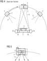
- figure 4 shows the movement of an X-ray emitter 4 of an FFS X-ray system 1 figure 1 during a tomosynthesis examination according to the prior art.
- the X-ray emitter 4 guided by the rotary arm 8, moves continuously along an arc of a circle along the arrow and radiates an X-ray beam R, which is collimated by a collimator diaphragm C, onto the object O to be examined on the detector 5.
- the X-ray emitter 4 moves along a distance a during an X-ray projection, which lasts a certain time.
- the central position during the X-ray projection is shown as a solid line and the start and end positions are shown as dots (the X-ray projection takes place between the start and end position).
- the angle of the X-ray beam R thus moves, which leads to a smearing of the picture taken.
- FFS tracking This movement artifact is avoided by FFS tracking, which always keeps the focal point in the central position (indicated by solid lines).
- FIG 5 shows an example of FFS tracking during a tomosynthesis examination. Shown is again the uppermost point of the circular path with the starting position (solid here) and the end position (dotted) of the X-ray emitter 4, in which the anode A is also indicated here.
- the electron beam E the hits the anode A from above in the image plane, first deflected to the right and later to the left (arrows), so that the point of impact on the anode A (focus point) is always in one position over the entire movement of the X-ray emitter 4 during this X-ray projection stays in the room.
- figure 6 shows a flowchart for a possible sequence of a method according to the invention for controlling an FFS X-ray system 1 as is shown, for example, in figure 1 is shown.
- a control data record D generated, which alone already enables control, but also an image is recorded and reconstructed.
- step I a beam geometry of the x-ray beam R is first simulated with a predetermined FFS deflection onto the detector 5 while a projection image P is being recorded.
- the projection image does not have to be actually recorded since all the necessary information is available.
- step II a determination is made as to whether a predetermined area around the detector 5 is overexposed by the simulated X-ray beam R.
- Detector 5 is shown here from above (square) and an irradiated area (circle) on detector 5. As can be seen, the circle extends beyond the edges of the detector, which corresponds to overexposure.
- step III FFS control data DF is generated for the recording (of a projection image P), which, if there is overexposure for the recording, causes an FFS deflection for this recording that is reduced compared to the specified FFS deflection, and otherwise cause the specified FFS deflection.
- diaphragm control data DB for tracking a collimator diaphragm C and/or beam control data DS for controlling the intensity of the X-ray beam R can be generated.
- a control data record D is generated comprising the generated FFS control data DF and, if necessary, additional aperture control data DB and/or beam control data DS for controlling an FFS X-ray system 1.
- step V a large number of projection images P are produced (recorded), the x-ray beam R of the x-ray emitter 4 being switched on and off many times during its circular movement.
- step VI layer images S are reconstructed from the recorded projection images P, with data from projection images P being weighted differently based on the control data set D during the reconstruction, with weighting being lower the greater the reduction in FFS deflection.
Landscapes
- Health & Medical Sciences (AREA)
- Life Sciences & Earth Sciences (AREA)
- Engineering & Computer Science (AREA)
- Medical Informatics (AREA)
- General Health & Medical Sciences (AREA)
- Pathology (AREA)
- Biomedical Technology (AREA)
- Biophysics (AREA)
- High Energy & Nuclear Physics (AREA)
- Veterinary Medicine (AREA)
- Nuclear Medicine, Radiotherapy & Molecular Imaging (AREA)
- Optics & Photonics (AREA)
- Public Health (AREA)
- Radiology & Medical Imaging (AREA)
- Physics & Mathematics (AREA)
- Heart & Thoracic Surgery (AREA)
- Molecular Biology (AREA)
- Surgery (AREA)
- Animal Behavior & Ethology (AREA)
- Toxicology (AREA)
- Computer Vision & Pattern Recognition (AREA)
- Dentistry (AREA)
- Oral & Maxillofacial Surgery (AREA)
- Apparatus For Radiation Diagnosis (AREA)
Priority Applications (2)
| Application Number | Priority Date | Filing Date | Title |
|---|---|---|---|
| EP21218102.8A EP4205657B1 (fr) | 2021-12-29 | 2021-12-29 | Procédé et système de commande d'un système à rayons x ffs |
| US18/146,704 US12383210B2 (en) | 2021-12-29 | 2022-12-27 | Method and system for controlling an FFS X-ray system |
Applications Claiming Priority (1)
| Application Number | Priority Date | Filing Date | Title |
|---|---|---|---|
| EP21218102.8A EP4205657B1 (fr) | 2021-12-29 | 2021-12-29 | Procédé et système de commande d'un système à rayons x ffs |
Publications (3)
| Publication Number | Publication Date |
|---|---|
| EP4205657A1 true EP4205657A1 (fr) | 2023-07-05 |
| EP4205657B1 EP4205657B1 (fr) | 2026-01-28 |
| EP4205657C0 EP4205657C0 (fr) | 2026-01-28 |
Family
ID=79024580
Family Applications (1)
| Application Number | Title | Priority Date | Filing Date |
|---|---|---|---|
| EP21218102.8A Active EP4205657B1 (fr) | 2021-12-29 | 2021-12-29 | Procédé et système de commande d'un système à rayons x ffs |
Country Status (2)
| Country | Link |
|---|---|
| US (1) | US12383210B2 (fr) |
| EP (1) | EP4205657B1 (fr) |
Families Citing this family (2)
| Publication number | Priority date | Publication date | Assignee | Title |
|---|---|---|---|---|
| CN120164585A (zh) * | 2023-12-15 | 2025-06-17 | 上海联影医疗科技股份有限公司 | 扫描图像生成方法、系统、设备和计算机可读存储介质 |
| CN118948312B (zh) * | 2024-08-29 | 2025-01-28 | 广州七喜医疗设备有限公司 | 一种乳腺机控制束光器的通信方法及装置 |
Citations (1)
| Publication number | Priority date | Publication date | Assignee | Title |
|---|---|---|---|---|
| DE102018221559A1 (de) * | 2018-12-12 | 2020-06-18 | Siemens Healthcare Gmbh | Tomosyntheseeinrichtung mit einem bewegten Röntgenstrahler |
Family Cites Families (15)
| Publication number | Priority date | Publication date | Assignee | Title |
|---|---|---|---|---|
| US5651047A (en) * | 1993-01-25 | 1997-07-22 | Cardiac Mariners, Incorporated | Maneuverable and locateable catheters |
| ATE547803T1 (de) * | 2007-06-21 | 2012-03-15 | Koninkl Philips Electronics Nv | Schnelle dosismodulierung über z-deflektion in einer rotierenden anode oder einer rotierenden rahmenröhre |
| US7869571B2 (en) * | 2008-09-17 | 2011-01-11 | General Electric Company | Methods and apparatus for x-ray imaging with focal spot deflection |
| CN102176866B (zh) * | 2008-11-24 | 2013-10-16 | 霍罗吉克公司 | 控制用于体层合成和乳房x射线照相术成像的x射线焦斑特性的方法和系统 |
| US8515005B2 (en) * | 2009-11-23 | 2013-08-20 | Hologic Inc. | Tomosynthesis with shifting focal spot and oscillating collimator blades |
| WO2011053972A2 (fr) * | 2009-11-02 | 2011-05-05 | Xrsciences Llc | Source de rayons x à double énergie à commutation rapide |
| US9517041B2 (en) * | 2011-12-05 | 2016-12-13 | Controlrad Systems Inc. | X-ray tube |
| EP2802897A4 (fr) * | 2012-01-11 | 2016-09-21 | Controlrad Systems Inc | Tube à rayons x |
| US8923484B2 (en) * | 2012-08-31 | 2014-12-30 | General Electric Company | Motion correction system and method for an x-ray tube |
| US9895124B2 (en) * | 2013-07-26 | 2018-02-20 | Hitachi, Ltd. | X-ray CT apparatus and image reconstruction method |
| JP6990457B2 (ja) * | 2016-10-19 | 2022-01-12 | アダプティックス リミテッド | X線源 |
| JP7376448B2 (ja) * | 2020-09-28 | 2023-11-08 | 富士フイルム株式会社 | 制御装置、制御方法、及び制御プログラム |
| US11633168B2 (en) * | 2021-04-02 | 2023-04-25 | AIX Scan, Inc. | Fast 3D radiography with multiple pulsed X-ray sources by deflecting tube electron beam using electro-magnetic field |
| DE102021210851B3 (de) * | 2021-09-28 | 2023-03-02 | Siemens Healthcare Gmbh | Verfahren und System zur Kalibration eines Röntgenstrahlers |
| DE102021210897A1 (de) * | 2021-09-29 | 2023-03-30 | Siemens Healthcare Gmbh | System zur Kalibration und/oder zur Qualitätskontrolle eines FFS-Röntgensystems |
-
2021
- 2021-12-29 EP EP21218102.8A patent/EP4205657B1/fr active Active
-
2022
- 2022-12-27 US US18/146,704 patent/US12383210B2/en active Active
Patent Citations (1)
| Publication number | Priority date | Publication date | Assignee | Title |
|---|---|---|---|---|
| DE102018221559A1 (de) * | 2018-12-12 | 2020-06-18 | Siemens Healthcare Gmbh | Tomosyntheseeinrichtung mit einem bewegten Röntgenstrahler |
Non-Patent Citations (1)
| Title |
|---|
| M. KACHELRIESS ET AL: "Flying focal spot (FFS) in cone-beam CT", IEEE TRANSACTIONS ON NUCLEAR SCIENCE, vol. 53, no. 3, 1 June 2006 (2006-06-01), pages 1238 - 1247, XP055114678, ISSN: 0018-9499, DOI: 10.1109/TNS.2006.874076 * |
Also Published As
| Publication number | Publication date |
|---|---|
| US12383210B2 (en) | 2025-08-12 |
| EP4205657B1 (fr) | 2026-01-28 |
| EP4205657C0 (fr) | 2026-01-28 |
| US20230200754A1 (en) | 2023-06-29 |
Similar Documents
| Publication | Publication Date | Title |
|---|---|---|
| EP1294445B1 (fr) | Dispositif pour irradier un tissu tumoral | |
| DE102008050571A1 (de) | Tomosynthesegerät und Verfahren zum Betrieb eines Tomosynthesegerätes | |
| DE102010035920A1 (de) | Verfahren zur Darstellung eines vorbestimmten Volumenabschnitts eines Untersuchungsobjekts mittels eines Tomosynthesegeräts und entsprechendes Tomosynthesegerät | |
| DE19650545A1 (de) | Kollimationseinrichtung zur Verringerung der Röntgenstrahldosis für den Patienten | |
| DE102008019128A1 (de) | Vorrichtung zur Durchführung einer Bestrahlung und Verfahren zur Überwachung einer solchen | |
| DE102004028035A1 (de) | Vorrichtung und Verfahren zur Kompensation von Bewegungen eines Zielvolumens während einer Ionenstrahl-Bestrahlung | |
| DE102009057066A1 (de) | Bildgebungsvorrichtung, Strahlentherapiegerät mit einer derartigen Bildgebungsvorrichtung, Verfahren zur Erzeugung eines Bildes und Computerprogrammprodukt | |
| EP1883093A2 (fr) | Tomodensitomètre | |
| DE102011007741B4 (de) | Verfahren und Computertomographiegerät zur dynamischen CT-Untersuchung eines Patienten sowie Datenträger | |
| EP4205657B1 (fr) | Procédé et système de commande d'un système à rayons x ffs | |
| DE102010042683B4 (de) | Einrichtung und Verfahren zur Erzeugung von Röntgenstrahlung sowie Rechenprogramm und Datenträger | |
| DE102011080263B4 (de) | Vorrichtung zur Röntgenbildgebung für Projektionsradiographie und Computertomographie sowie ein entsprechend ausgebildetes Verfahren zur Röntgenbildgebung | |
| WO2006082028A1 (fr) | Appareil de tomographie a geometrie d'image variable | |
| EP4125110B1 (fr) | Tube à rayons x pour une imagerie stéréoscopique | |
| EP1776044B1 (fr) | Appareil d'imagerie medicale | |
| DE102017207512A1 (de) | Justage-Verfahren für einen Markierungslaserstrahl, entsprechendes Justage-System und Bildgebungsmodalität | |
| EP4327747B1 (fr) | Procédé mis en oevre par ordinateur pour faire fonctionner un dispositif à rayons x et dispositif à rayons x | |
| DE2723462A1 (de) | Roentgendiagnostikgeraet fuer transversalschichtbilder | |
| DE102010041781A1 (de) | Verfahren und ein CT-Gerät zur computertomographischen Spiralabtastung eines Patienten | |
| EP3628229A1 (fr) | Génération d'une image de résultat | |
| DE102021211885B4 (de) | Computerimplementiertes Verfahren zum Betrieb einer Röntgeneinrichtung, Röntgeneinrichtung, Computerprogramm und elektronisch lesbarer Datenträger | |
| WO2018077603A2 (fr) | Procédé pour générer des radiographies et système radiographique | |
| DE102015223074A1 (de) | Selbstjustierendes Röntgenbildgebungsverfahren für die stereotaktische Biopsie | |
| DE102021210897A1 (de) | System zur Kalibration und/oder zur Qualitätskontrolle eines FFS-Röntgensystems | |
| DE102018221559B4 (de) | Tomosyntheseeinrichtung mit einem bewegten Röntgenstrahler |
Legal Events
| Date | Code | Title | Description |
|---|---|---|---|
| PUAI | Public reference made under article 153(3) epc to a published international application that has entered the european phase |
Free format text: ORIGINAL CODE: 0009012 |
|
| STAA | Information on the status of an ep patent application or granted ep patent |
Free format text: STATUS: THE APPLICATION HAS BEEN PUBLISHED |
|
| AK | Designated contracting states |
Kind code of ref document: A1 Designated state(s): AL AT BE BG CH CY CZ DE DK EE ES FI FR GB GR HR HU IE IS IT LI LT LU LV MC MK MT NL NO PL PT RO RS SE SI SK SM TR |
|
| STAA | Information on the status of an ep patent application or granted ep patent |
Free format text: STATUS: REQUEST FOR EXAMINATION WAS MADE |
|
| 17P | Request for examination filed |
Effective date: 20231205 |
|
| RBV | Designated contracting states (corrected) |
Designated state(s): AL AT BE BG CH CY CZ DE DK EE ES FI FR GB GR HR HU IE IS IT LI LT LU LV MC MK MT NL NO PL PT RO RS SE SI SK SM TR |
|
| RAP1 | Party data changed (applicant data changed or rights of an application transferred) |
Owner name: SIEMENS HEALTHINEERS AG |
|
| STAA | Information on the status of an ep patent application or granted ep patent |
Free format text: STATUS: EXAMINATION IS IN PROGRESS |
|
| 17Q | First examination report despatched |
Effective date: 20250103 |
|
| GRAP | Despatch of communication of intention to grant a patent |
Free format text: ORIGINAL CODE: EPIDOSNIGR1 |
|
| STAA | Information on the status of an ep patent application or granted ep patent |
Free format text: STATUS: GRANT OF PATENT IS INTENDED |
|
| RIC1 | Information provided on ipc code assigned before grant |
Ipc: A61B 6/02 20060101AFI20250910BHEP Ipc: A61B 6/00 20060101ALI20250910BHEP Ipc: A61B 6/40 20240101ALI20250910BHEP Ipc: A61B 6/50 20240101ALI20250910BHEP |
|
| INTG | Intention to grant announced |
Effective date: 20250918 |
|
| GRAS | Grant fee paid |
Free format text: ORIGINAL CODE: EPIDOSNIGR3 |
|
| GRAA | (expected) grant |
Free format text: ORIGINAL CODE: 0009210 |
|
| STAA | Information on the status of an ep patent application or granted ep patent |
Free format text: STATUS: THE PATENT HAS BEEN GRANTED |
|
| AK | Designated contracting states |
Kind code of ref document: B1 Designated state(s): AL AT BE BG CH CY CZ DE DK EE ES FI FR GB GR HR HU IE IS IT LI LT LU LV MC MK MT NL NO PL PT RO RS SE SI SK SM TR |
|
| REG | Reference to a national code |
Ref country code: CH Ref legal event code: F10 Free format text: ST27 STATUS EVENT CODE: U-0-0-F10-F00 (AS PROVIDED BY THE NATIONAL OFFICE) Effective date: 20260128 Ref country code: GB Ref legal event code: FG4D Free format text: NOT ENGLISH |
|
| REG | Reference to a national code |
Ref country code: IE Ref legal event code: FG4D Free format text: LANGUAGE OF EP DOCUMENT: GERMAN |
|
| U01 | Request for unitary effect filed |
Effective date: 20260128 |
|
| U07 | Unitary effect registered |
Designated state(s): AT BE BG DE DK EE FI FR IT LT LU LV MT NL PT RO SE SI Effective date: 20260203 |
|
| PG25 | Lapsed in a contracting state [announced via postgrant information from national office to epo] |
Ref country code: RS Free format text: LAPSE BECAUSE OF FAILURE TO SUBMIT A TRANSLATION OF THE DESCRIPTION OR TO PAY THE FEE WITHIN THE PRESCRIBED TIME-LIMIT Effective date: 20260428 |
|
| PG25 | Lapsed in a contracting state [announced via postgrant information from national office to epo] |
Ref country code: ES Free format text: LAPSE BECAUSE OF FAILURE TO SUBMIT A TRANSLATION OF THE DESCRIPTION OR TO PAY THE FEE WITHIN THE PRESCRIBED TIME-LIMIT Effective date: 20260128 |
|
| PG25 | Lapsed in a contracting state [announced via postgrant information from national office to epo] |
Ref country code: PL Free format text: LAPSE BECAUSE OF FAILURE TO SUBMIT A TRANSLATION OF THE DESCRIPTION OR TO PAY THE FEE WITHIN THE PRESCRIBED TIME-LIMIT Effective date: 20260128 |
|
| PG25 | Lapsed in a contracting state [announced via postgrant information from national office to epo] |
Ref country code: GR Free format text: LAPSE BECAUSE OF FAILURE TO SUBMIT A TRANSLATION OF THE DESCRIPTION OR TO PAY THE FEE WITHIN THE PRESCRIBED TIME-LIMIT Effective date: 20260429 |
|
| PG25 | Lapsed in a contracting state [announced via postgrant information from national office to epo] |
Ref country code: NO Free format text: LAPSE BECAUSE OF FAILURE TO SUBMIT A TRANSLATION OF THE DESCRIPTION OR TO PAY THE FEE WITHIN THE PRESCRIBED TIME-LIMIT Effective date: 20260428 |
|
| PG25 | Lapsed in a contracting state [announced via postgrant information from national office to epo] |
Ref country code: HR Free format text: LAPSE BECAUSE OF FAILURE TO SUBMIT A TRANSLATION OF THE DESCRIPTION OR TO PAY THE FEE WITHIN THE PRESCRIBED TIME-LIMIT Effective date: 20260128 |
|
| PG25 | Lapsed in a contracting state [announced via postgrant information from national office to epo] |
Ref country code: IS Free format text: LAPSE BECAUSE OF FAILURE TO SUBMIT A TRANSLATION OF THE DESCRIPTION OR TO PAY THE FEE WITHIN THE PRESCRIBED TIME-LIMIT Effective date: 20260528 |