EP4205687A1 - Dispositif de pince - Google Patents
Dispositif de pince Download PDFInfo
- Publication number
- EP4205687A1 EP4205687A1 EP20953279.5A EP20953279A EP4205687A1 EP 4205687 A1 EP4205687 A1 EP 4205687A1 EP 20953279 A EP20953279 A EP 20953279A EP 4205687 A1 EP4205687 A1 EP 4205687A1
- Authority
- EP
- European Patent Office
- Prior art keywords
- pulley
- grasping portion
- grasping
- guide
- rotating shaft
- Prior art date
- Legal status (The legal status is an assumption and is not a legal conclusion. Google has not performed a legal analysis and makes no representation as to the accuracy of the status listed.)
- Ceased
Links
Images





Classifications
-
- A—HUMAN NECESSITIES
- A61—MEDICAL OR VETERINARY SCIENCE; HYGIENE
- A61B—DIAGNOSIS; SURGERY; IDENTIFICATION
- A61B17/00—Surgical instruments, devices or methods
- A61B17/28—Surgical forceps
- A61B17/29—Forceps for use in minimally invasive surgery
-
- A—HUMAN NECESSITIES
- A61—MEDICAL OR VETERINARY SCIENCE; HYGIENE
- A61B—DIAGNOSIS; SURGERY; IDENTIFICATION
- A61B34/00—Computer-aided surgery; Manipulators or robots specially adapted for use in surgery
- A61B34/30—Surgical robots
-
- A—HUMAN NECESSITIES
- A61—MEDICAL OR VETERINARY SCIENCE; HYGIENE
- A61B—DIAGNOSIS; SURGERY; IDENTIFICATION
- A61B34/00—Computer-aided surgery; Manipulators or robots specially adapted for use in surgery
- A61B34/70—Manipulators specially adapted for use in surgery
- A61B34/71—Manipulators operated by drive cable mechanisms
-
- A—HUMAN NECESSITIES
- A61—MEDICAL OR VETERINARY SCIENCE; HYGIENE
- A61B—DIAGNOSIS; SURGERY; IDENTIFICATION
- A61B17/00—Surgical instruments, devices or methods
- A61B17/28—Surgical forceps
- A61B17/29—Forceps for use in minimally invasive surgery
- A61B2017/2901—Details of shaft
- A61B2017/2902—Details of shaft characterized by features of the actuating rod
- A61B2017/2903—Details of shaft characterized by features of the actuating rod transferring rotary motion
-
- A—HUMAN NECESSITIES
- A61—MEDICAL OR VETERINARY SCIENCE; HYGIENE
- A61B—DIAGNOSIS; SURGERY; IDENTIFICATION
- A61B34/00—Computer-aided surgery; Manipulators or robots specially adapted for use in surgery
- A61B34/30—Surgical robots
- A61B2034/305—Details of wrist mechanisms at distal ends of robotic arms
Definitions
- the present invention relates to a forceps device used for a manipulator of a surgical robot.
- Patent Literature 1 teaches forceps including two jaw parts serving as grasping portions, two disks having different outer diameters from each other provided on the respective jaw parts, and wires running over the disks. The wires are pulled to open or close the jaw parts.
- Patent Literature 1 US 2015/0127045 A1
- deflection rollers for making fleet angles of the wires smaller are provided between a disk over which a wire that is pulled for bending the whole jaw parts and a disk provided on the jaw parts.
- some distance is needed between a rotation axis of bending of the whole jaw parts and a rotation axis of opening and closing of the jaw parts. The torque therefore reduces at the leading end of the forceps and the controllability thus lowers as compared with forceps with a short distance between the rotation axes.
- the present invention has been made in view of the aforementioned circumstances, and an exemplary object thereof is to provide a forceps device with high controllability.
- a forceps device includes: a grasping part; a support that holds the grasping part; a first rotating shaft that turnably supports the support; a base member that holds the first rotating shaft; a plurality of guide pulleys arranged coaxially with the first rotating shaft; a plurality of grasping portion wires running over the guide pulleys and the grasping part without other pulleys therebetween and transmitting driving force to move the grasping part; a support pulley provided on the support; and a support wire running over the support pulley and transmitting driving force to turn the support about the first rotating shaft.
- the distance between the first rotating shaft and the second rotating shaft can be shortened, and the torque of the grasping part can therefore be increased.
- a forceps device with high controllability of the grasping part can be provided.
- the grasping part may include a first grasping portion and second grasping portion that move relative to each other to grasp an object.
- the first grasping portion may be continuous with a first grasping portion pulley and a second grasping portion pulley, which constitute a bifurcated shape
- the second grasping portion may be continuous with a third grasping portion pulley and a fourth grasping portion pulley, which constitute a bifurcated shape.
- the forceps device may further include a second rotating shaft that rotatably supports the first grasping portion pulley, the third grasping portion pulley, the second grasping portion pulley, and the fourth grasping portion pulley arranged in this order.
- the device includes: a grasping part; a support that holds the grasping part; a first rotating shaft that turnably supports the support; a base member that holds the first rotating shaft; a plurality of guide pulleys arranged coaxially with the first rotating shaft; and a plurality of grasping portion wires running over the guide pulleys and the grasping part without other pulleys therebetween and transmitting driving force to move the grasping part.
- the grasping part includes a first grasping portion and second grasping portion that move relative to each other to grasp an object.
- the first grasping portion is continuous with a first grasping portion pulley and a second grasping portion pulley, which constitute a bifurcated shape
- the second grasping portion is continuous with a third grasping portion pulley and a fourth grasping portion pulley, which constitute a bifurcated shape
- the forceps device further includes a second rotating shaft that rotatably supports the first grasping portion pulley, the third grasping portion pulley, the second grasping portion pulley, and the fourth grasping portion pulley arranged in this order.
- the distance between the first rotating shaft and the second rotating shaft can be shortened, and the torque of the grasping part can therefore be increased.
- a forceps device with high controllability of the grasping part can be provided.
- the support may include a cylindrical part through which the first rotating shaft extends.
- the guide pulleys are rotatably supported by an outer circumference of the cylindrical part.
- the guide pulleys may include first to fourth guide pulleys.
- the grasping portion wires may be passed over the first to fourth guide pulleys and the first to fourth grasping portion pulleys without other pulleys therebetween.
- the grasping portion wires may include: a first grasping portion wire running over the first guide pulley and the third grasping portion pulley; a second grasping portion wire running over the second guide pulley and the first grasping portion pulley; a third grasping portion wire running over the third guide pulley and the second grasping portion pulley; and a fourth grasping portion wire running over the fourth guide pulley and the fourth grasping portion pulley.
- the first grasping portion wire may be passed over a first side of the first guide pulley with respect to a vertical cross section including the first rotating shaft and being perpendicular to the second rotating shaft, and then fixed to the third grasping portion pulley located on the first side with respect to the vertical cross section
- the second grasping portion wire may be passed over the first side of the second guide pulley with respect to the vertical cross section, and then fixed to the first grasping portion pulley located on the first side with respect to the vertical cross section
- the third grasping portion wire may be passed over a second side of the third guide pulley with respect to the vertical cross section, and then fixed to the second grasping portion pulley located on the second side with respect to the vertical cross section
- the fourth grasping portion wire may be passed over the second side of the fourth guide pulley with respect to the vertical cross section, and then fixed to the fourth grasping portion pulley with respect to the vertical cross section.
- the four grasping portion wires are fixed to the four grasping portion pulleys, respectively, without intersecting with each other.
- the four grasping portion wires running over the first to fourth guide pulleys are fixed to the four grasping portion pulleys, respectively, with small fleet angles.
- the aforementioned forceps device may further include: a fifth guide pulley located on an upstream side of the first guide pulley and on the second side with respect to the vertical cross section; a sixth guide pulley located on an upstream side of the second guide pulley and on the second side with respect to the vertical cross section; a seventh guide pulley located on an upstream side of the third guide pulley and on the first side with respect to the vertical cross section; and an eighth guide pulley located on an upstream side of the fourth guide pulley and on the first side with respect to the vertical cross section.
- a forceps device with high controllability can be achieved.
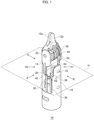
- FIG. 1 is a perspective view of a forceps device according to an embodiment.
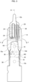
- FIG. 2 is a front view of the forceps device of FIG. 1 as viewed in a direction A.
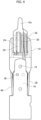
- FIG. 3 is a side view of the forceps device of FIG. 1 as viewed in a direction B.
- FIG. 4 is a side view of the forceps device of FIG. 1 as viewed in a direction C.
- the forceps device 10 illustrated in the drawings includes a pair of grasping portions 12a and 12b, a support 14 that holds the pair of grasping portions 12a and 12b, a first rotating shaft 16 that turnably supports the support 14, a base member 18 that holds the first rotating shaft 16, four guide pulleys 20 arranged coaxially with the first rotating shaft 16, a second rotating shaft 22 that turnably supports the pair of grasping portions 12a and 12b and is held by the support 14, four jaw pulleys 24 supported coaxially with the second rotating shaft 22, four wires 26, 28, 30 and 32 running over the four guide pulleys 20 and the four jaw pulleys 24, and wires 38 and 40 for rotating the support 14 about the first rotating shaft 16.
- FIG. 5 is a cross-sectional view of the forceps device 10 illustrated in FIG. 3 along D-D.
- FIG. 6 is an enlarged view of a region R in FIG. 5 .
- the guide pulleys 20 are rotatably supported by the first rotating shaft 16 with an annular part 14a having a cylindrical shape, which is part of the support 14, therebetween and at an angle with respect to the first rotating shaft 16.
- the respective wires 26, 28, 30 and 32 have small substantial fleet angles with respect to the guide pulleys 20, and therefore become less likely to interfere with edges 20b of guide grooves 20a of the guide pulleys 20.
- the guide pulleys 20 may be directly supported by the first rotating shaft 16 without the support 14 therebetween.
- FIG. 7 is a front view of a guide pulley 20 according to the embodiment.
- FIG. 8 is a cross-sectional view of the guide pulley 20 illustrated in FIG. 7 along E-E.
- Each guide pulley 20 according to the embodiment has an inner circumferential face 20d tilted with respect to a center line CL of a circular opening 20c thereof through which the first rotating shaft 16 extends.
- the inner circumferential face 20d slides relative to the annular part 14a of the support 14 into which the first rotating shaft 16 is inserted.
- the guide pulleys 20 are autonomously tilted due to the forces received from wires having fleet angles.
- the inner circumferential face 20d of each guide pulley 20 slides directly relative to the outer circumferential face of the first rotating shaft 16.
- the inner circumferential face 20d of each guide pulley 20 is formed so that the inner diameter d of the guide pulley 20 gradually increases from the position of a plane P, which is perpendicular to the center line CL and at which the inner diameter d is smallest, as the position is farther along the center line CL from the plane P.
- the inner circumferential face 20d may have a conical shape, an inverted cone shape, or a tapered shape.
- an inner circumferential face 20e opposite the inner circumferential face 20d with respect to the plane P is also processed to have a shape similar to the inner circumferential face 20d.
- each of the guide pulleys 20 is formed such that the angle ⁇ between the inner circumferential face 20d or the inner circumferential face 20e and the center line CL is within a range from 3 to 7 degrees.
- one end face 20f of each guide pulley 20 is tilted at the angle ⁇ with respect to the plane P, and the angle between the end face 20f and the inner circumferential face 20d is 90°.
- the other end face 20g of the guide pulley 20 is parallel to the plane P (perpendicular to the center line CL).
- Each guide pulley 20 is therefore an annular member that is asymmetric with respect to the plane P.
- the guide pulleys 20 are arranged in such a manner that two guide pulleys 20 are arranged adjacent to each other on each side of the support 14 with the support 14 therebetween.
- the end faces 20g of two guide pulleys 20 that are arranged adjacent to each other on the annular part 14a face each other.
- one (a guide pulley 20B) of two guide pulleys 20 that are adjacent to each other is in contact with and tilted with respect to the support 14, and the other (a guide pulley 20A) of the two guide pulleys 20 adjacent to each other is in contact with and tilted with respect to the base member 18.
- the guide pulley 20 is accurately positioned in a first rotating shaft direction X.
- the guide pulleys 20 are each tilted with respect to the first rotating shaft 16 so that the wires 26 and 28 running over the guide pulleys 20 extend out toward the outer circumference of the jaw pulleys 24.
- the wires 26 and 28 running over the guide pulleys 20 extend out toward the outer circumference of the jaw pulleys 24.
- the base member 18 As illustrated in FIG. 2 and FIG. 5 , the base member 18 according to the embodiment includes a pair of arms 18a and 18b that hold respective ends of the first rotating shaft 16, and third rotating shafts 36 that are held by the pair of arms 18a and 18b, respectively, and rotatably support four guide pulleys 34 located upstream of the guide pulleys 20. Note that a third rotating shaft 36 according to the embodiment is provided on each of the pair of arms 18a and 18b.
- the arms 18a and 18b each have a base part 18c holding the third rotating shaft 36, and a distal end part 18d that holds the first rotating shaft 16 and that is thinner than the base part 18c.
- the distance between the distal end parts 18d is larger than the distance between the base parts 18c.
- the circumferential width W1 of the distal end part 18d of the arm 18a (the arm 18b) is smaller than the circumferential width W2 of the base part 18c thereof.
- a U-shaped recess is formed at the distal end part 18d at which interference with a wire needs to be addressed, and the circumferential width of the distal end part 18d is made larger than the circumferential width of the base part 18c, which minimizes deterioration of the stiffness of the arm.
- the jaw pulleys 24 according to the embodiment have an outer diameter G1, which is larger than the distance between the base parts 18c of the pair of arms 18a and 18b.
- the jaw pulleys 24 having a large outer diameter relative to the inner diameter of the cylindrical base member 18 may be used.
- FIG. 9 is a perspective view of the support according to the embodiment.
- the forceps device 10 includes the pair of grasping portions 12a and 12b, the support 14 that holds the pair of grasping portions 12a and 12b, the first rotating shaft 16 that turnably supports the support 14, the base member 18 that holds the first rotating shaft 16, and a plurality of guide pulleys 20 arranged coaxially with the first rotating shaft 16.
- the support 14 has the annular part 14a, which is a cylindrical part through which the first rotating shaft 16 extends.
- the guide pulleys 20 are rotatably supported by the outer circumference of the annular part 14a.
- each rotating shaft is not limited to a shaft that rotates by itself, but may be any shaft that is the center of rotation of a member supported thereby, and may be a shaft fixed to another member.
- the support 14 in a state in which a plurality of guide pulleys 20 are supported by the outer circumference of the annular part 14a is held by the base member 18 with the first rotating shaft 16 therebetween.
- This configuration facilitates improvement in the easiness of assembly as compared with a case where the support 14 is held directly by the base member 18.
- the base member 18 of the embodiment has the pair of arms 18a and 18b facing each other.
- the first rotating shaft 16 is firmly fixed in such a manner that the axial ends thereof are press-fitted to the pair of arms 18a and 18b.
- Each of the wires 26, 28, 30 and 32 transmits a driving force to the grasping portion 12a or the grasping portion 12b to move the grasping portion 12a or the grasping portion 12b.
- the wire 26 and the wire 32 run over the jaw pulleys 24 for the grasping portion 12b, and the grasping portion 12b moves in an opening direction when the wire 26 is pulled and moves in a closing direction when the wire 32 is pulled.
- the wire 28 and the wire 30 run over the jaw pulleys 24 for the grasping portion 12a, and the grasping portion 12a moves in a closing direction when the wire 28 is pulled and moves in an opening direction when the wire 30 is pulled.
- each of the four guide pulleys 20 has a corresponding one of the wires 26, 28, 30 and 32 placed thereover.
- Each of the wires 26, 28, 30 and 32 runs over the corresponding one of the guide pulleys 20 so that the normal force applied to the support 14 from the first rotating shaft 16 is reduced when the grasping portions 12a and 12b are moved. More specifically, as illustrated in FIG. 2 , each of the wires 26, 28, 30 and 32 passes between the corresponding ones of the guide pulleys 20 and guide pulleys 34 and runs over the corresponding one of the guide pulleys 20 from a lower side thereof (a side opposite the grasping portion 12a or 12b with respect to the first rotating shaft 16) .
- the tension applied to the wires 26, 28, 30 and 32 causes a force acting on the support 14 via the guide pulleys 20.
- the tension applied to the wires 26, 28, 30 and 32 causes a force acting on the support 14 in directions toward the grasping portions 12a and 12b.
- the support 14 is formed integrally with a support pulley 42 over which the wires 38 and 40 for transmitting a driving force for rotating the support about the first rotating shaft 16 run.
- a support pulley 42 over which the wires 38 and 40 for transmitting a driving force for rotating the support about the first rotating shaft 16 run.
- the tension of the wires 26, 28, 30 and 32 for moving the grasping portions 12a and 12b causes a force acting on the guide pulleys 20 in the upward direction in FIG. 2 as described above.
- the normal force caused by the wires 38 and 40 is reduced by the force acting on the guide pulleys 20, which reduces the frictional force when the support 14 turns about the first rotating shaft 16. Consequently, the movement of the grasping portions 12a and 12b becomes smoother, and the controllability of the forceps device 10 improves.
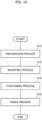
- FIG. 10 is a flowchart explaining a method for manufacturing the forceps device according to the embodiment.
- the support 14 holding the grasping portions 12a and 12b is first prepared (S10).
- a plurality of guide pulleys 20 are mounted on the outer circumference of the annular part 14a through which a through-hole 44 (see FIG. 5 ) is formed (S12).
- the first rotating shaft 16 that turnably supports the support 14 is to be inserted in the through-hole 44.
- the support 14 is positioned so that holes 18e and 18f into which the first rotating shaft 16 is to be inserted and the through-hole 44 are linearly aligned with respect the base member 18 through which the holes 18e and 18f are formed (S14).
- the first rotating shaft 16 is then inserted into the hole 18e, and the respective ends of the first rotating shaft 16 are ultimately press-fitted into the holes 18e and 18f of the base member 18, so that the first rotating shaft 16 is firmly fixed to the base member 18 (S16).
- a process of passing wires over the pulleys may be performed at a timing that does not interfere with the manufacture described above.
- such a process as sandwiching a support by base member parts into which a base member is divided and then bonding the base member parts to each other need not be performed.
- such a process as coaxially arranging holes of a support, pulleys and a base member, and press-fitting a rotating shaft into the support while keeping the positions of the holes, which involves difficult adjustment, need not be performed.
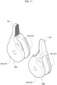
- FIG. 11 is a perspective view illustrating a state in which a pair of jaw parts facing each other are to be fitted according to the embodiment.
- Jaw parts 50A and 50B illustrated in FIG. 11 are parts having substantially the same shapes as each other.
- the jaw parts 50A and 50B have the grasping portion 12a and the grasping portion 12b, respectively, which move relative to each other to grasp an object.
- the grasping portion 12a is continuous with a jaw pulley 24a (first grasping portion pulley) and a jaw pulley 24b (second grasping portion pulley), which are formed in a bifurcated shape, and the grasping portion 12a and the jaw pulleys 24a and 24b integrally constitute the jaw part 50A.
- the grasping portion 12b is continuous with a jaw pulley 24c (third grasping portion pulley) and a jaw pulley 24d (fourth grasping portion pulley), which are formed in a bifurcated shape, and the grasping portion 12b and the jaw pulleys 24c and 24d integrally constitute the jaw part 50B.
- FIG. 12 is a perspective view of the forceps device 10 illustrated in FIG. 1 as viewed in a direction H1.
- FIG. 13 is a perspective view of the forceps device 10 illustrated in FIG. 1 as viewed in a direction H2.
- FIG. 14 is a perspective view of the forceps device 10 illustrated in FIG. 1 as viewed in a direction H3.
- FIG. 15 is a perspective view of the forceps device 10 illustrated in FIG. 1 as viewed in a direction opposite the direction H2.
- the directions H1 to H3 are directions within a horizontal plane H including the first rotating shaft 16.
- the base member 18 is not illustrated in FIGS. 12 to 15 .
- the jaw pulley 24a, the jaw pulley 24c, the jaw pulley 24b, and the jaw pulley 24d are rotatably supported in this order by the second rotating shaft 22.
- the guide pulley 20A, the guide pulley 20B, the guide pulley 20C, and the guide pulley 20D are rotatably supported in this order by the first rotating shaft 16.
- the wires 26, 28, 30 and 32, which are grasping portion wires for transmitting driving forces for causing the grasping portions 12a and 12b to perform opening and closing movements, run between the guide pulleys 20A to 20D and the grasping portions 12a and 12b without other pulleys.
- the driving forces are input from an actuator unit outside of the forceps device 10.
- This configuration can shorten the distance between the first rotating shaft 16 and the second rotating shaft 22 as illustrated in FIG. 12 , etc., and can therefore increase the torque (operation force) of the grasping portions 12a and 12b. Consequently, the forceps device 10 with high controllability of the grasping portions 12a and 12b can be provided.
- the wire 26 runs between the guide pulley 20A and the jaw pulley 24c.
- the wire 28 runs between the guide pulley 20B and the jaw pulley 24a.
- the wire 30 runs between the guide pulley 20C and the jaw pulley 24b.
- the wire 32 runs between the guide pulley 20D and the jaw pulley 24d.
- FIG. 16 is a view of the forceps device 10 illustrated in FIG. 3 without illustration of the base member 18.
- FIG. 17 is a view of the forceps device 10 illustrated in FIG. 4 without illustration of the base member.
- the wire 26 is passed over a first side S1 of the guide pulley 20A with respect to a vertical cross section V including the first rotating shaft 16 and being perpendicular to the second rotating shaft 22, and then fixed to the jaw pulley 24c located on the first side S1 with respect to the vertical cross section V.
- the wire 28 is passed over the first side S1 of the guide pulley 20B with respect to the vertical cross section V, and then fixed to the jaw pulley 24a located on the first side S1 with respect to the vertical cross section V.
- the wire 30 is passed over the second side S2 of the guide pulley 20C with respect to the vertical cross section V, and then fixed to the jaw pulley 24b located on the second side with respect to the vertical cross section V.
- the wire 32 is passed over the second side S2 of the guide pulley 20D with respect to the vertical cross section V, and then fixed to the jaw pulley 24d located on the second side S2 with respect to the vertical cross section V.
- the four grasping portion wires are fixed to the four grasping portion pulleys, respectively, without intersecting with each other.
- the four grasping portion wires running over the guide pulleys 20A to 20D are fixed to the four grasping portion pulleys, respectively, with small fleet angles.
- the forceps device 10 includes the guide pulley 34a on the upstream side of the guide pulley 20A (on the side opposite the grasping portions) and on the second side S2 with respect to the vertical cross section V, the guide pulley 34b on the upstream side of the guide pulley 20B and on the second side S2 with respect to the vertical cross section V, the guide pulley 34c on the upstream side of the guide pulley 20C and on the first side S1 with respect to the vertical cross section V, and the guide pulley 34d on the upstream side of the guide pulley 20D and on the first side S1 with respect to the vertical cross section V.
- the present invention can be used for a manipulator of a surgical robot.
Landscapes
- Health & Medical Sciences (AREA)
- Surgery (AREA)
- Life Sciences & Earth Sciences (AREA)
- Engineering & Computer Science (AREA)
- Medical Informatics (AREA)
- Biomedical Technology (AREA)
- Heart & Thoracic Surgery (AREA)
- Nuclear Medicine, Radiotherapy & Molecular Imaging (AREA)
- Molecular Biology (AREA)
- Animal Behavior & Ethology (AREA)
- General Health & Medical Sciences (AREA)
- Public Health (AREA)
- Veterinary Medicine (AREA)
- Robotics (AREA)
- Ophthalmology & Optometry (AREA)
- Manipulator (AREA)
- Surgical Instruments (AREA)
Applications Claiming Priority (1)
| Application Number | Priority Date | Filing Date | Title |
|---|---|---|---|
| PCT/JP2020/034370 WO2022054214A1 (fr) | 2020-09-10 | 2020-09-10 | Dispositif de pince |
Publications (2)
| Publication Number | Publication Date |
|---|---|
| EP4205687A1 true EP4205687A1 (fr) | 2023-07-05 |
| EP4205687A4 EP4205687A4 (fr) | 2024-02-21 |
Family
ID=76540437
Family Applications (1)
| Application Number | Title | Priority Date | Filing Date |
|---|---|---|---|
| EP20953279.5A Ceased EP4205687A4 (fr) | 2020-09-10 | 2020-09-10 | Dispositif de pince |
Country Status (5)
| Country | Link |
|---|---|
| US (1) | US20230210546A1 (fr) |
| EP (1) | EP4205687A4 (fr) |
| JP (1) | JP6896317B1 (fr) |
| CN (1) | CN115916089B (fr) |
| WO (1) | WO2022054214A1 (fr) |
Families Citing this family (2)
| Publication number | Priority date | Publication date | Assignee | Title |
|---|---|---|---|---|
| WO2023135792A1 (fr) * | 2022-01-17 | 2023-07-20 | リバーフィールド株式会社 | Dispositif de pince |
| WO2025099560A1 (fr) * | 2023-11-08 | 2025-05-15 | Covidien Lp | Instrument chirurgical à mâchoires articulées ayant une poulie libre pour un angle de déflexion nul |
Family Cites Families (12)
| Publication number | Priority date | Publication date | Assignee | Title |
|---|---|---|---|---|
| ATE534338T1 (de) * | 2006-10-13 | 2011-12-15 | Terumo Corp | Manipulator |
| US8771270B2 (en) * | 2008-07-16 | 2014-07-08 | Intuitive Surgical Operations, Inc. | Bipolar cautery instrument |
| DE102012212510B4 (de) | 2012-07-17 | 2014-02-13 | Richard Wolf Gmbh | Endoskopisches Instrument |
| CN106572889B (zh) * | 2014-08-13 | 2019-09-06 | 柯惠Lp公司 | 机器人控制的具有机械优势的夹持 |
| CN105212987B (zh) * | 2015-09-29 | 2018-03-16 | 哈尔滨思哲睿智能医疗设备有限公司 | 一种手术微器械的末端执行机构 |
| JP2017093818A (ja) * | 2015-11-25 | 2017-06-01 | リバーフィールド株式会社 | 撮像システムおよび固定具 |
| GB201521812D0 (en) * | 2015-12-10 | 2016-01-27 | Cambridge Medical Robotics Ltd | Driving a surgical instrument articulation |
| JP6799132B2 (ja) * | 2017-02-27 | 2020-12-09 | 朝日インテック株式会社 | マニピュレータ |
| US10973600B2 (en) * | 2017-09-29 | 2021-04-13 | Ethicon Llc | Power axle wrist for robotic surgical tool |
| CN107928792A (zh) * | 2017-12-11 | 2018-04-20 | 哈尔滨思哲睿智能医疗设备有限公司 | 一种用于微创外科机器人用多自由度持针器 |
| CN112566567B (zh) * | 2018-08-17 | 2024-10-29 | 奥瑞斯健康公司 | 双极医疗器械 |
| WO2022054213A1 (fr) * | 2020-09-10 | 2022-03-17 | リバーフィールド株式会社 | Dispositif de pince et procédé de production d'un dispositif de pince |
-
2020
- 2020-09-10 JP JP2021507719A patent/JP6896317B1/ja active Active
- 2020-09-10 CN CN202080103538.9A patent/CN115916089B/zh active Active
- 2020-09-10 EP EP20953279.5A patent/EP4205687A4/fr not_active Ceased
- 2020-09-10 WO PCT/JP2020/034370 patent/WO2022054214A1/fr not_active Ceased
-
2023
- 2023-03-09 US US18/181,034 patent/US20230210546A1/en not_active Abandoned
Also Published As
| Publication number | Publication date |
|---|---|
| CN115916089B (zh) | 2025-04-18 |
| EP4205687A4 (fr) | 2024-02-21 |
| US20230210546A1 (en) | 2023-07-06 |
| JPWO2022054214A1 (fr) | 2022-03-17 |
| JP6896317B1 (ja) | 2021-06-30 |
| CN115916089A (zh) | 2023-04-04 |
| WO2022054214A1 (fr) | 2022-03-17 |
Similar Documents
| Publication | Publication Date | Title |
|---|---|---|
| US20230210546A1 (en) | Forceps device | |
| US12310691B2 (en) | Multi-cable medical instrument | |
| JP7491503B2 (ja) | 手術支援ロボット用インスツルメント | |
| AU2008233014B2 (en) | A multi-linked device having a reinforcing member | |
| EP4252693B1 (fr) | Dispositif de pince et composant de base | |
| WO2012157169A1 (fr) | Robot industriel à articulations multiples | |
| WO2024022048A1 (fr) | Mécanisme d'effecteur terminal d'instrument chirurgical, et instrument chirurgical | |
| CN115835828A (zh) | 外科手术机械臂、柔性臂以及柔性关节 | |
| JP6850517B1 (ja) | 鉗子装置及び鉗子装置の製造方法 | |
| EP3395280A1 (fr) | Élément d'activation, mécanisme d'activation et procédé de fabrication de mécanisme d'activation | |
| KR20100099817A (ko) | 수술기구 | |
| JP2002536196A (ja) | ロボットマニピュレータ及び方法 | |
| EP4458307B1 (fr) | Dispositif de pince | |
| WO2018207809A1 (fr) | Dispositif d'actionnement de fil et procédé de retenue pour fil | |
| EP4458287B1 (fr) | Dispositif de pince | |
| JP6867073B1 (ja) | 鉗子装置 | |
| EP4461251A1 (fr) | Dispositif de pince | |
| JP2013244562A (ja) | 関節装置及びリンク機構 | |
| US20200000318A1 (en) | Cable actuation mechanism for steerable endoscope | |
| KR102919647B1 (ko) | 다양한 직경의 타겟을 그립할 수 있는 소프트 그리퍼 및 이를 구비한 로봇 시스템 | |
| KR102830444B1 (ko) | 웨어러블 로봇용 비간섭 케이블 구동 회전 관절 장치 |
Legal Events
| Date | Code | Title | Description |
|---|---|---|---|
| STAA | Information on the status of an ep patent application or granted ep patent |
Free format text: STATUS: THE INTERNATIONAL PUBLICATION HAS BEEN MADE |
|
| PUAI | Public reference made under article 153(3) epc to a published international application that has entered the european phase |
Free format text: ORIGINAL CODE: 0009012 |
|
| STAA | Information on the status of an ep patent application or granted ep patent |
Free format text: STATUS: REQUEST FOR EXAMINATION WAS MADE |
|
| 17P | Request for examination filed |
Effective date: 20230330 |
|
| AK | Designated contracting states |
Kind code of ref document: A1 Designated state(s): AL AT BE BG CH CY CZ DE DK EE ES FI FR GB GR HR HU IE IS IT LI LT LU LV MC MK MT NL NO PL PT RO RS SE SI SK SM TR |
|
| RIC1 | Information provided on ipc code assigned before grant |
Ipc: A61B 34/00 20160101ALI20231026BHEP Ipc: A61B 17/28 20060101ALI20231026BHEP Ipc: A61B 34/30 20160101AFI20231026BHEP |
|
| DAV | Request for validation of the european patent (deleted) | ||
| DAX | Request for extension of the european patent (deleted) | ||
| A4 | Supplementary search report drawn up and despatched |
Effective date: 20231220 |
|
| RIC1 | Information provided on ipc code assigned before grant |
Ipc: A61B 34/00 20160101ALI20231214BHEP Ipc: A61B 17/28 20060101ALI20231214BHEP Ipc: A61B 34/30 20160101AFI20231214BHEP |
|
| RIC1 | Information provided on ipc code assigned before grant |
Ipc: A61B 34/00 20160101ALI20231221BHEP Ipc: A61B 17/28 20060101ALI20231221BHEP Ipc: A61B 34/30 20160101AFI20231221BHEP |
|
| DA4 | Supplementary search report drawn up and despatched (deleted) | ||
| RA4 | Supplementary search report drawn up and despatched (corrected) |
Effective date: 20240112 |
|
| RIC1 | Information provided on ipc code assigned before grant |
Ipc: A61B 34/00 20160101ALI20240108BHEP Ipc: A61B 17/28 20060101ALI20240108BHEP Ipc: A61B 34/30 20160101AFI20240108BHEP |
|
| RA4 | Supplementary search report drawn up and despatched (corrected) |
Effective date: 20240119 |
|
| RIC1 | Information provided on ipc code assigned before grant |
Ipc: A61B 34/00 20160101ALI20240115BHEP Ipc: A61B 17/28 20060101ALI20240115BHEP Ipc: A61B 34/30 20160101AFI20240115BHEP |
|
| STAA | Information on the status of an ep patent application or granted ep patent |
Free format text: STATUS: EXAMINATION IS IN PROGRESS |
|
| 17Q | First examination report despatched |
Effective date: 20240919 |
|
| REG | Reference to a national code |
Ref country code: DE Ref legal event code: R003 |
|
| STAA | Information on the status of an ep patent application or granted ep patent |
Free format text: STATUS: THE APPLICATION HAS BEEN REFUSED |
|
| 18R | Application refused |
Effective date: 20251118 |