EP4205929A1 - Vertikaler holzspalter mit drehbarem auflagetisch - Google Patents
Vertikaler holzspalter mit drehbarem auflagetisch Download PDFInfo
- Publication number
- EP4205929A1 EP4205929A1 EP22212967.8A EP22212967A EP4205929A1 EP 4205929 A1 EP4205929 A1 EP 4205929A1 EP 22212967 A EP22212967 A EP 22212967A EP 4205929 A1 EP4205929 A1 EP 4205929A1
- Authority
- EP
- European Patent Office
- Prior art keywords
- log splitter
- vertical
- pin
- shaft
- support
- Prior art date
- Legal status (The legal status is an assumption and is not a legal conclusion. Google has not performed a legal analysis and makes no representation as to the accuracy of the status listed.)
- Withdrawn
Links
- 238000010276 construction Methods 0.000 claims description 15
- 230000002787 reinforcement Effects 0.000 claims description 5
- 230000001174 ascending effect Effects 0.000 claims description 2
- 238000009434 installation Methods 0.000 description 6
- 239000002023 wood Substances 0.000 description 5
- 230000000977 initiatory effect Effects 0.000 description 2
- 239000000463 material Substances 0.000 description 2
- 230000001419 dependent effect Effects 0.000 description 1
- 230000004224 protection Effects 0.000 description 1
Images




Classifications
-
- B—PERFORMING OPERATIONS; TRANSPORTING
- B27—WORKING OR PRESERVING WOOD OR SIMILAR MATERIAL; NAILING OR STAPLING MACHINES IN GENERAL
- B27L—REMOVING BARK OR VESTIGES OF BRANCHES; SPLITTING WOOD; MANUFACTURE OF VENEER, WOODEN STICKS, WOOD SHAVINGS, WOOD FIBRES OR WOOD POWDER
- B27L7/00—Arrangements for splitting wood
-
- B—PERFORMING OPERATIONS; TRANSPORTING
- B27—WORKING OR PRESERVING WOOD OR SIMILAR MATERIAL; NAILING OR STAPLING MACHINES IN GENERAL
- B27L—REMOVING BARK OR VESTIGES OF BRANCHES; SPLITTING WOOD; MANUFACTURE OF VENEER, WOODEN STICKS, WOOD SHAVINGS, WOOD FIBRES OR WOOD POWDER
- B27L7/00—Arrangements for splitting wood
- B27L7/005—Hand tools therefor
-
- B—PERFORMING OPERATIONS; TRANSPORTING
- B27—WORKING OR PRESERVING WOOD OR SIMILAR MATERIAL; NAILING OR STAPLING MACHINES IN GENERAL
- B27L—REMOVING BARK OR VESTIGES OF BRANCHES; SPLITTING WOOD; MANUFACTURE OF VENEER, WOODEN STICKS, WOOD SHAVINGS, WOOD FIBRES OR WOOD POWDER
- B27L7/00—Arrangements for splitting wood
- B27L7/06—Arrangements for splitting wood using wedges, knives or spreaders
Definitions
- the present invention belongs to the field of forestry machines, more precisely to the field of devices for splitting and chopping wood, and is particularly related to accessories for easier splitting of wood logs.
- the invention relates to a vertical log splitter with a rotatable support table.
- Known splitting devices have different splitting or cutting means that are configured to split wood into smaller parts.
- vertical log splitters have splitting axes attached on a plate that slides along a vertical guide upwards and downwards, wherein the wood placed below the splitting axe is split during the downward movement.
- Said log part may be placed directly on the bottom plate of the log splitter or on a support table, depending on the size of the log to be split.
- Some known solutions do not have the support table, for example log splitters according to documents FR2466323 , US4905746 , and US2016136839 .
- Utility model CN212266116 discloses a vertical log splitter that does not have a support table, but ensures fixation of the log to be split with a special enclosing mechanism.
- Patent AT398928 discloses a fixation mechanism, however, this solution grips the log from the sides in order to prevent its movement.
- patent application US2020269375 does not describe a support table, but has a rotatable mechanism installed on the bottom of the log splitter, wherein said rotatable mechanism enables log rotation.
- a problem of known vertical log splitters equipped with the support table is in that these tables are separate units that have to be separately transported and installed, which complicated and prolongs work. Applicable standards prohibit use of the support table for shorter logs, in case the table does not have an ergonomic height for multi-hour work, wherein the ergonomic height is 90 cm. Consequently, if the support table has a working height of at least 90 cm, the table may be sold together with the log splitter and not as an accessory.
- the technical problem which is solved by the present invention, is a constructional solution of the vertical log splitter and the support table that will fulfil requirements of standards and will enable simple installation and use.
- Utility model CN210551944 discloses a device with a base plate on which a vertical support is provided, wherein a splitting axes is movable along said vertical support.
- a support plate In the middle of the vertical support a support plate is provided in a fixed manner. Said support plate cannot be removed due to the fixed mounting, which means that only logs of a particular length can be split.
- Utility model CN208543591 describes a vertical log splitter with a support table, which is enclosed from two sides with protections that prevent the logs from slipping from the table.
- the surface of the table has anti-slip layers that additionally restrict movement of the log. This document does not disclose how the table is attached to the log splitter.
- Patent application BE896055 discloses to a splitting device with a frame comprising a holder in which a splitting axe is installed on the bottom of the device.
- the splitting axe is movable along the height with a lifting mechanism.
- Patent SI25215 relates to a vertical log splitter with a wedge and a table, which is attached to the vertical guide, wherein the height of the table is adjustable.
- the table consists of an upper part and a lower part, the latter being guided in a movable manner in the upper part to the installed edge on the lower part.
- One side of the lower part to the middle of the edge has height A and the opposite side to the middle of the edge has height B, which is the height A increased for the desired height difference for two table heights.
- Described solutions differ from the present invention in that none of them allows temporary removal of the table from the working area of the log splitter.
- the invention is based on the vertical log splitter, wherein the log or a part of wood for splitting is placed below the axe, which perpendicularly to the floor pushes onto the log with a certain splitting force.
- the technical problem of the construction of a table having an active (working) and non-active position, in which the support table is not in the working area of the log splitter, and which can be set to an ergonomic height of at least 90 cm, is solved as defined in the independent claim, wherein preferred embodiments are defined in the dependent claims.
- the log splitter has a base plate on which a vertical pillar is mounted, along which a splitting axe is moving downwards (splitting) and upwards (return movement), and other important known parts of the log splitter.
- the essence of the log splitter according to the invention is in that it is equipped with a rotatable support table, which is designed as a working surface installed on a support leg, wherein:
- the support leg may be a single element or comprises two or more parts, wherein each of the parts is attached to the rod or the shaft in the same manner as the above-described single-piece support leg.
- the connecting element is one or more, depending on the size of the support leg and its parts. In case shorter logs are to be split, height of the table has to be increased, thus all parts of the support table are rotated. In case of longer logs, only the upper part(s) of the support leg with the work surface are rotated to achieve smaller height. In case of the latter, the upper part(s) of the support leg descend on the rod or the shaft, as the lower part(s) will not be supporting the upper part(s).
- Each of the parts of the support leg is provided with a suitable locking mechanism for locking rotation and a mounting on the base plate of the log splitter.
- the base plate of the log splitter is preferably provided with a space arranged to receive the support leg of the table, in order to ensure improved installation on or into the base plate, which additionally limits movement of the table during application of the splitting force on the log placed on the support table.
- An additional role in this has a pin for locking the position of the table, which may be a straight or a curved pin arranged to be installed through an eyelet on a bottom part of the support leg and in a hole in the base plate of the log splitter. This pin prevents movement of the table and also maintains the distance from the pillar.
- Manipulation of the pin is preferably manual, but it could be automatic in case the pin was installed in the base plate and in case it was designed as a pushing or a sinking pin that is compressed during passage of the support leg and again raised once the pin is positionally corresponding to the hole or the eyelet in the bottom part of the support leg.
- the locking mechanism for locking rotation around the shaft may be any suitable mechanism known to the skilled person.
- the preferred embodiment of the locking mechanism is designed in the following manner: an upper bushing installed on the shaft for connection with the connecting element a holder with a hole is provided, said hole being arranged to receive the straight pin, while a lower bushing is provided with two cylindrical accessories, wherein the first accessory is arranged to receive the pin in the active position of the table, and the second accessory is arranged to receive the pin in the inactive position of the table.
- Matching of the pin with one of the cylindrical accessories depends on the position of the table, which affects the position of the lower bushing and consequently the cylindrical accessories.
- the rotatable table is on the shaft or rotational mechanism optionally equipped with springs, which are not essential for operation, but are intended for easier lifting of the table prior to rotation between positions or changing of the position of the table.
- springs instead of springs, obliquely cut bushings arranged to allow lifting of the table along an ascending part and to allow descent along a descending part may be used. This may be further assisted with optional threads on the rod, which prevent excessive or too fast movement.
- the log splitter according to the invention is further equipped with an adjustable construction which ensures the log splitter to be lifted and fixed at a height that fulfils standard requirements. Lifting of the log splitter is achieved with the lifting hydraulics of the tractor, which is also used for lifting and transporting the log splitter to a work place or station. Such lifts are thus common.
- the adjustable construction that enables the height of support table of at least 90 cm may be designed as:
- Said carrying frame may have on the opposite side from the vertical guides an additional supporting element, which is rotatably mounted on the side of the bottom frame and is in its elevated position engaged in a pre-prepared groove in the bottom part of the base plate of the log splitter.
- Use of the log splitter with the rotatable table comprises the steps of removing the pin or opening the locking mechanism, lifting the table slightly and then rotating it in the direction towards the axis, and then setting the table in the required position on the base plate, followed by locking the position with the second pin.
- the pin and the rotational mechanism pin are unlocked, then the table is slightly lifted and rotated to the inactive position, followed by locking the position with the pin of the rotational mechanism.
- the height of the support table may be selected using the above-described solutions.
- the geometry of the rotational table ensures a storage space for logs, which are temporarily placed or leaned against the shaft. Because the fulcrum for table rotation is not on the pillar of the log splitter and is at a distance form it, this storage space is ensured.
- the invention enables that the complete installation of the table from the inactive into the active position is performed by one person without the need for moving or removing elements, as locking is achieved with the suitable locking mechanism.
- the rotatable table is safely installed and enables reliable and safe use during log splitting.
- Construction of the rotatable table is suitable for the vertical log splitter as well as any other devices or machines having working tables with active and inactive positions.
- Figure 1 shows a possible embodiment of the log splitter, wherein the log splitter has a base plate 1 with installed vertical pillar 2 along which a splitting axe 3 is moved downwards (splitting) and upwards (return movement) as well as other important known components of the log splitter known to the skilled person that are not directly related to the present invention.
- the log splitter is equipped with a rotatable table 4, which is designed as a work surface 41 installed on a support leg 42, wherein:
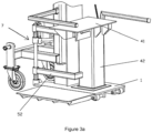
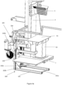
- FIGS. 2 and 3 The active and inactive position of the rotatable table of the log splitter are shown in figures 2 and 3 with details.
- the support table is out of reach of the splitting axe, i.e., outside the base plate 1 of the log splitter.
- the base plate 1 of the log splitter is provided with a space 1b for receiving the support leg 42 of the table, into which the support leg corresponds in the active position of the table, thus ensuring stable position of the table.
- FIG. 3c also clearly depicts the shape of connecting elements 5, wherein the upper 51 is shaped as a straight rod attached to the support 41a of the work surface 41, while the lower 52 is shaped as the letter L. Both are mounted on the shaft via bushings.
- the adjustable construction which enables that the support table has a height of at least 90 cm from the floor may be designed as a carrying frame shown in figure 4a or as carrying legs shown in figure 4b .
- Figure 4a shows a carrying frame 100 comprising a bottom rectangular frame 101 with optional triangular or polygonal reinforcements 102a in at least two corners, and two vertical guides 103 that are perpendicular to the bottom frame 101, wherein a connecting leg of the log splitter with a guide 104 is installed on the vertical guides 103, said guide 104 being movable along the vertical guides 103, and wherein the connections between the bottom frame 101 and the vertical guides 103 are reinforced with approximately triangular, trapezoid or polygonal reinforcements 102b, and wherein the vertical guides 103 are provided with holes 103a, into which a pin 105 can be installed in order to fix the position of the log splitter ( figure 4a ).
- Said carrying frame 101 may have on the opposite side from the vertical guides 103 an additional supporting element (not shown in the figures), which is rotatably mounted on the side 101a of the bottom frame 101 and is in its elevated position engaged in a pre-prepared groove (not shown in the figures) in the bottom part of the base plate of the log splitter.
- the adjustable construction 110 is designed as four carrying (support) legs 111, which are installed in the pre-prepared openings 112 in the base plate of the log splitter as shown in figure 4b .
- the position of said carrying legs is fixed with any suitable attachment element, preferably with a pin 113 having suitable dimensions and made from a material that sustains large loads ( figure 4b ).
Landscapes
- Life Sciences & Earth Sciences (AREA)
- Engineering & Computer Science (AREA)
- Wood Science & Technology (AREA)
- Forests & Forestry (AREA)
- Workshop Equipment, Work Benches, Supports, Or Storage Means (AREA)
Applications Claiming Priority (1)
| Application Number | Priority Date | Filing Date | Title |
|---|---|---|---|
| SI202100227A SI26284A (sl) | 2021-12-20 | 2021-12-20 | Vertikalni cepilnik drv z zasukljivo podporno mizo |
Publications (1)
| Publication Number | Publication Date |
|---|---|
| EP4205929A1 true EP4205929A1 (de) | 2023-07-05 |
Family
ID=84799713
Family Applications (1)
| Application Number | Title | Priority Date | Filing Date |
|---|---|---|---|
| EP22212967.8A Withdrawn EP4205929A1 (de) | 2021-12-20 | 2022-12-12 | Vertikaler holzspalter mit drehbarem auflagetisch |
Country Status (2)
| Country | Link |
|---|---|
| EP (1) | EP4205929A1 (de) |
| SI (1) | SI26284A (de) |
Citations (13)
| Publication number | Priority date | Publication date | Assignee | Title |
|---|---|---|---|---|
| FR2466323A1 (fr) | 1979-09-27 | 1981-04-10 | Bordet Andre | Fendeuse hydraulique et appareil de manutention |
| BE896055A (fr) | 1983-03-01 | 1983-07-01 | Geets Michel | Cadre a fendre les buches grace a n'importe quel cric automobile |
| US4561479A (en) * | 1984-04-04 | 1985-12-31 | Burdine Charles M | Mechanical wood splitter |
| US4905746A (en) | 1989-04-19 | 1990-03-06 | Claude Bedard | Log splitter |
| AT398928B (de) | 1993-06-15 | 1995-02-27 | Posch Landmaschinenbau | Trenn- und spalteinrichtung |
| DE202015000697U1 (de) * | 2015-01-29 | 2015-03-03 | Georg Blümel | Mobiler Holzspalter / Drillkegelspalter mit Verbrennungsmotor |
| US20160136839A1 (en) | 2013-06-21 | 2016-05-19 | Bernard Michael CONROY | A log splitter, and a method for splitting a log |
| SI25215A (sl) | 2016-06-03 | 2017-12-29 | Uniforest D.O.O. | Vertikalni cepilnik drv s klinom z izboljšano mizo |
| CN208543591U (zh) | 2018-06-27 | 2019-02-26 | 昌信(莱州)机电科技有限公司 | 一种立式劈木机 |
| EP3597727A1 (de) * | 2018-07-20 | 2020-01-22 | Pisek - Vitli Krpan, d.o.o. | Verbesserte gleitplatten für einen holzspalter und holzspalter mit diesen gleitplatten |
| CN210551944U (zh) | 2019-07-18 | 2020-05-19 | 嘉善雪帕尔工具有限公司 | 一种新型欠压过流保护器的锂电劈木机 |
| US20200269375A1 (en) | 2019-02-26 | 2020-08-27 | Gerald Rowley | Wood Splitting Turntable Assembly |
| CN212266116U (zh) | 2020-04-03 | 2021-01-01 | 江阴市亿鑫隆机械科技有限公司 | 一种立式劈木机的抱木装置 |
-
2021
- 2021-12-20 SI SI202100227A patent/SI26284A/sl active IP Right Grant
-
2022
- 2022-12-12 EP EP22212967.8A patent/EP4205929A1/de not_active Withdrawn
Patent Citations (13)
| Publication number | Priority date | Publication date | Assignee | Title |
|---|---|---|---|---|
| FR2466323A1 (fr) | 1979-09-27 | 1981-04-10 | Bordet Andre | Fendeuse hydraulique et appareil de manutention |
| BE896055A (fr) | 1983-03-01 | 1983-07-01 | Geets Michel | Cadre a fendre les buches grace a n'importe quel cric automobile |
| US4561479A (en) * | 1984-04-04 | 1985-12-31 | Burdine Charles M | Mechanical wood splitter |
| US4905746A (en) | 1989-04-19 | 1990-03-06 | Claude Bedard | Log splitter |
| AT398928B (de) | 1993-06-15 | 1995-02-27 | Posch Landmaschinenbau | Trenn- und spalteinrichtung |
| US20160136839A1 (en) | 2013-06-21 | 2016-05-19 | Bernard Michael CONROY | A log splitter, and a method for splitting a log |
| DE202015000697U1 (de) * | 2015-01-29 | 2015-03-03 | Georg Blümel | Mobiler Holzspalter / Drillkegelspalter mit Verbrennungsmotor |
| SI25215A (sl) | 2016-06-03 | 2017-12-29 | Uniforest D.O.O. | Vertikalni cepilnik drv s klinom z izboljšano mizo |
| CN208543591U (zh) | 2018-06-27 | 2019-02-26 | 昌信(莱州)机电科技有限公司 | 一种立式劈木机 |
| EP3597727A1 (de) * | 2018-07-20 | 2020-01-22 | Pisek - Vitli Krpan, d.o.o. | Verbesserte gleitplatten für einen holzspalter und holzspalter mit diesen gleitplatten |
| US20200269375A1 (en) | 2019-02-26 | 2020-08-27 | Gerald Rowley | Wood Splitting Turntable Assembly |
| CN210551944U (zh) | 2019-07-18 | 2020-05-19 | 嘉善雪帕尔工具有限公司 | 一种新型欠压过流保护器的锂电劈木机 |
| CN212266116U (zh) | 2020-04-03 | 2021-01-01 | 江阴市亿鑫隆机械科技有限公司 | 一种立式劈木机的抱木装置 |
Also Published As
| Publication number | Publication date |
|---|---|
| SI26284A (sl) | 2023-06-30 |
Similar Documents
| Publication | Publication Date | Title |
|---|---|---|
| EP2260229B1 (de) | Höhenverstellbarer geräteständer | |
| US20020043776A1 (en) | Mobile machinary base | |
| EP4205929A1 (de) | Vertikaler holzspalter mit drehbarem auflagetisch | |
| EP1972737B1 (de) | Gerüstanordnung | |
| CN110355732B (zh) | 工作台 | |
| KR20140086385A (ko) | 선박용 모터의 커플링 조립장치 | |
| EP1992586A2 (de) | Mechanismus zur Abstandsangleichung zwischen dem ersten und zweiten Stützträger | |
| US20110156365A1 (en) | Lift wheel set used in a machine tool | |
| KR20140146465A (ko) | 선체 블록 서포트 기구 및 그 사용방법 | |
| KR102526245B1 (ko) | 벽면패널 부착장치 | |
| US20100303593A1 (en) | Adjustable lift dolly which is used in connection with stand-mounted equipment, power tools and similer items | |
| JP2016064493A (ja) | 作業台 | |
| CN211565701U (zh) | 一种断路器搬运小车 | |
| US11059701B2 (en) | Methods and apparatuses for lifting elevator cars during installation | |
| KR101955416B1 (ko) | 중장비를 이용하여 승강 및 좌우 이동이 가능한 선미 축/타계 작업대 | |
| CN219469617U (zh) | 一种叉车护顶架调节结构 | |
| CN216918473U (zh) | 一种可移动的剪叉式升降平台 | |
| CN221251203U (zh) | 转辙机搬移装置 | |
| CN215617768U (zh) | 一种电动汽车的后桥与电机系统组合体的拆装工具 | |
| CN111546428A (zh) | 摇摆圆锯 | |
| CN217625540U (zh) | 一种堆垛托盘定位装置 | |
| KR102576676B1 (ko) | 기둥거푸집 이동설치용 지게차 부속장치 및 브라켓 세트 | |
| CN214993170U (zh) | 一种便于调节的桥梁工程施工用升降台 | |
| KR960000111B1 (ko) | 포오크리프트의 푸시풀장치 | |
| KR102727252B1 (ko) | 가구 제작용 보드 절단 장치 |
Legal Events
| Date | Code | Title | Description |
|---|---|---|---|
| PUAI | Public reference made under article 153(3) epc to a published international application that has entered the european phase |
Free format text: ORIGINAL CODE: 0009012 |
|
| STAA | Information on the status of an ep patent application or granted ep patent |
Free format text: STATUS: THE APPLICATION HAS BEEN PUBLISHED |
|
| AK | Designated contracting states |
Kind code of ref document: A1 Designated state(s): AL AT BE BG CH CY CZ DE DK EE ES FI FR GB GR HR HU IE IS IT LI LT LU LV MC ME MK MT NL NO PL PT RO RS SE SI SK SM TR |
|
| STAA | Information on the status of an ep patent application or granted ep patent |
Free format text: STATUS: THE APPLICATION IS DEEMED TO BE WITHDRAWN |
|
| 18D | Application deemed to be withdrawn |
Effective date: 20240106 |