EP4206152A1 - Dispositif de changement d'outil pour un dispositif de formage de récipients en verre - Google Patents
Dispositif de changement d'outil pour un dispositif de formage de récipients en verre Download PDFInfo
- Publication number
- EP4206152A1 EP4206152A1 EP22213456.1A EP22213456A EP4206152A1 EP 4206152 A1 EP4206152 A1 EP 4206152A1 EP 22213456 A EP22213456 A EP 22213456A EP 4206152 A1 EP4206152 A1 EP 4206152A1
- Authority
- EP
- European Patent Office
- Prior art keywords
- tool holder
- tool
- guide tube
- receptacle
- receptacles
- Prior art date
- Legal status (The legal status is an assumption and is not a legal conclusion. Google has not performed a legal analysis and makes no representation as to the accuracy of the status listed.)
- Pending
Links
- 239000011521 glass Substances 0.000 claims abstract description 57
- 238000007493 shaping process Methods 0.000 claims abstract description 31
- 238000002347 injection Methods 0.000 claims abstract description 9
- 239000007924 injection Substances 0.000 claims abstract description 9
- 238000003780 insertion Methods 0.000 claims description 8
- 230000037431 insertion Effects 0.000 claims description 8
- 238000000034 method Methods 0.000 claims description 8
- 230000003287 optical effect Effects 0.000 claims description 3
- 238000007373 indentation Methods 0.000 claims description 2
- 238000004519 manufacturing process Methods 0.000 abstract description 5
- 230000008878 coupling Effects 0.000 description 13
- 238000010168 coupling process Methods 0.000 description 13
- 238000005859 coupling reaction Methods 0.000 description 13
- 238000000465 moulding Methods 0.000 description 12
- 230000008859 change Effects 0.000 description 11
- 230000000295 complement effect Effects 0.000 description 4
- 230000006835 compression Effects 0.000 description 4
- 238000007906 compression Methods 0.000 description 4
- 230000008569 process Effects 0.000 description 4
- 229940127554 medical product Drugs 0.000 description 3
- 230000002028 premature Effects 0.000 description 3
- 239000000243 solution Substances 0.000 description 3
- 230000004888 barrier function Effects 0.000 description 2
- 230000008901 benefit Effects 0.000 description 2
- 239000002537 cosmetic Substances 0.000 description 2
- 239000003814 drug Substances 0.000 description 2
- 229940079593 drug Drugs 0.000 description 2
- 230000000694 effects Effects 0.000 description 2
- 230000005484 gravity Effects 0.000 description 2
- 230000007257 malfunction Effects 0.000 description 2
- 229910052751 metal Inorganic materials 0.000 description 2
- 239000002184 metal Substances 0.000 description 2
- 229910001092 metal group alloy Inorganic materials 0.000 description 2
- 238000000926 separation method Methods 0.000 description 2
- WFKWXMTUELFFGS-UHFFFAOYSA-N tungsten Chemical compound [W] WFKWXMTUELFFGS-UHFFFAOYSA-N 0.000 description 2
- 229910052721 tungsten Inorganic materials 0.000 description 2
- 239000010937 tungsten Substances 0.000 description 2
- 229960005486 vaccine Drugs 0.000 description 2
- 230000009471 action Effects 0.000 description 1
- 238000010276 construction Methods 0.000 description 1
- 238000009434 installation Methods 0.000 description 1
- 239000000463 material Substances 0.000 description 1
- 230000013011 mating Effects 0.000 description 1
- 238000003032 molecular docking Methods 0.000 description 1
- 238000003825 pressing Methods 0.000 description 1
Images



Classifications
-
- C—CHEMISTRY; METALLURGY
- C03—GLASS; MINERAL OR SLAG WOOL
- C03B—MANUFACTURE, SHAPING, OR SUPPLEMENTARY PROCESSES
- C03B23/00—Re-forming shaped glass
- C03B23/04—Re-forming tubes or rods
- C03B23/045—Tools or apparatus specially adapted for re-forming tubes or rods in general, e.g. glass lathes, chucks
-
- C—CHEMISTRY; METALLURGY
- C03—GLASS; MINERAL OR SLAG WOOL
- C03B—MANUFACTURE, SHAPING, OR SUPPLEMENTARY PROCESSES
- C03B23/00—Re-forming shaped glass
- C03B23/04—Re-forming tubes or rods
- C03B23/09—Reshaping the ends, e.g. as grooves, threads or mouths
Definitions
- the invention relates to a tool changing device and a shaping device for shaping glass containers, in particular syringes, carpules and injection vials.
- an open end of a glass tube is shaped under the action of heat and shaping tools, for example shaping rollers.
- a tool is inserted into the open end of a glass tube in order to shape an inner shape of the glass container.
- the object of the invention is to increase the efficiency of the forming equipment used for forming glass containers.
- the tool changing device comprises at least two tool holder receptacles for receiving a respective tool holder, wherein the at least two tool holder receptacles can be moved from at least one loading and unloading position into an operating position, and one of the at least two tool holder receptacles is then in an loading and unloading position when another the at least two tool holder receptacles are arranged in the operating position, and wherein the at least two tool holder receptacles are each provided with a through-opening.
- the task is also solved by a tool holder for a tool changing device.
- the tool holder has a shank with a mount for one end of a guide tube and a mount opposite the mount for exchangeable attachment of a tool.
- this object is achieved by a method for shaping a glass container such as a syringe, carpule and injection bottle, wherein a tool holder with a tool for shaping an inner shape of the glass container is moved into an operating position and at the same time another tool holder is moved into an equipping and removal position.
- a method for shaping a glass container such as a syringe, carpule and injection bottle, wherein a tool holder with a tool for shaping an inner shape of the glass container is moved into an operating position and at the same time another tool holder is moved into an equipping and removal position.
- the advantage of the above solution is that a tool change can be carried out during operation.
- the tool is no longer directly attached to a guide tube fastened, but indirectly via the tool holder.
- a tool holder with a tool for shaping the inner shape of the glass container is used in the operating position
- another tool holder with a tool can be used in the loading and unloading position.
- the tool holder previously used in the loading and unloading position is brought into the operating position, the tool holder with the worn tool being moved into the loading and unloading position at the same time. From this moment the shaping of the glass container can be continued with the new tool.
- the worn tool in the tool holder located in the loading and unloading position can therefore be exchanged in peace and without influencing the shaping process.
- the quick tool change is particularly advantageous when shaping glass containers, since the tools are subject to a high level of wear, which reduces their diameter.
- a worn tool results in a change in the diameter of the inner shape of the glass container, which means that it is no longer dimensionally accurate.
- changing the tool is relatively time-consuming. Therefore, due to the long downtimes, there is a high loss of production with conventional molding equipment, which can be avoided by the tool changing device.
- the glass containers can, for example, have a maximum length or height of 20 cm or more and/or a maximum diameter of 6 cm.
- the glass containers are containers for medical products, such as vaccines or medicines, for cosmetic products and/or for food.
- Glass containers for medical products in particular are subject to strict regulations and high demands on the dimensional accuracy of the glass containers. Therefore, when shaping the glass containers, care must be taken to ensure that the tools reliably guarantee this dimensional accuracy.
- the push-through opening can be designed in particular for pushing through a guide tube for the tool holder.
- the guide tube can be held linearly movable relative to the through-opening, essentially parallel to an axial direction.
- the at least two tool holder receptacles are arranged on a common carrier.
- the carrier can preferably be plate-shaped and/or ring-shaped.
- the tool changing device can have a tool turret that can be rotated in a direction of rotation, on which the at least two tool holder receptacles are arranged at a distance from one another in the direction of rotation. It is particularly advantageous if the tool turret has a magazine ring that can be moved in the direction of rotation and has at least two tool holder receptacles. The round shape of the magazine ring allows a comparatively particularly space-saving design of the tool changing device.
- the tool turret can be driven in rotation.
- the tool turret can have a drive, by which the magazine ring is rotated about an axis of rotation of the magazine ring in the direction of rotation.
- the at least two tool holder receptacles can be arranged diametrically to one another, so that the at least one loading and unloading position is arranged as far away as possible from the operating position.
- the diametrical design allows simpler automation, since the magazine ring is rotated at the same interval for each tool change.
- the tool changing device can have a plurality of tool holder receptacles, in particular eight, preferably four.
- the tool holder receptacles can be arranged equigonally, i.e. at equal angular intervals on the magazine ring.
- one tool holder nest is located in the operative position, at least one of the other tool holder nests may be located in the loading and unloading position.
- loading and unloading positions can also be provided for each tool holder receptacle apart from the operating position.
- the loading position and the removal position can also be separated from one another.
- a removal position in which the tool holder with the worn tool is removed from the tool holder device, can be provided around a rotational position of the magazine ring behind the operating position in the direction of rotation.
- a loading position can be arranged around a rotational position of the magazine ring behind the removal position in the direction of rotation. The separation of the removal position and the loading position is particularly advantageous for automating the process.
- the separation allows a fully automated process, with a tool holder being removed from or inserted into the tool holder receptacle at the corresponding positions.
- the at least two tool holder receptacles can each be provided with a coding element for determining the orientation of a rotational position of the tool holder in the corresponding tool holder receptacle.
- the coding element can, for example, influence a contour of the tool holder receptacle in such a way that it is not rotationally symmetrical. In one embodiment, this can be achieved by a bulge, a projection or a depression in the radially inward-pointing surface of the tool holder receptacle.
- the tool holder can be designed to complement the contour of the tool holder receptacle, so that the tool holder can only be inserted into the tool holder receptacle in one possible rotational position.
- the tool changing device can have a tool holder which is inserted into one of the at least two tool holder receptacles, the tool holder being able to be pushed out of the tool holder receptacle.
- the tool holder can be loosely fitted in the tool holder seat, thereby facilitating the replacement of the tool holder.
- “Loose” here means that the tool holder is held in the tool holder receptacle mainly, in particular only, by gravity.
- the tool holder receptacle can be oversized relative to the tool holder, so that a clearance of, for example, 1 mm is formed in the radial direction between the tool holder and the wall of the tool holder receptacle pointing radially inwards.
- the tool holder can be inserted in a removable manner from the tool holder receptacle in an axial direction while the forming device is in operation.
- the axial direction can be directed essentially parallel to the axis of rotation of the magazine ring.
- the shank of the tool holder can protrude through the push-through opening of the tool holder receptacle when the tool holder is inserted in the tool holder receptacle.
- the tool holder can have a head that protrudes radially from the shank and has a bearing surface for bearing in the tool holder receptacle.
- the holder for the tool can preferably be arranged on the head.
- the mount can have an opening, for example in which the tool can be fixed.
- the tool can be fixed, for example, by one or two stud screws on the side.
- the holder in particular the opening of the holder, is preferably arranged essentially concentrically with the receptacle.
- the holder and the receptacle can be open on opposite sides.
- the opening of the holder can also protrude through the head and end in the receptacle.
- the concentric arrangement of the holder and the seat allows the tool to be aligned over the guide tube. Therefore, high changing accuracy can be secured in terms of the concentricity between the tool and the glass container.
- the receptacle can have a radially inward-pointing wall with indentations, in particular bores, spaced apart from one another in the circumferential direction. Pressing bodies of the guide tube which are complementary to the depressions can be pressed into the depressions, as a result of which the tool holder is connected to the guide tube both in a non-positive and positive manner.
- the configurations of the recesses spaced apart from one another in the circumferential direction have the advantage over a continuous groove in the circumferential direction that the rotational position of the tool holder relative to the guide tube is fixed by a positive fit in the circumferential direction between the tool holder and the guide tube.
- connection of the configuration with the depressions and the coding element facilitates the replacement of the tool holder or the insertion of the tool holder into the tool holder. Due to the coding element, the tool holder can already be inserted into the tool holder receptacle in a predetermined rotational position. Slight deviations from the predetermined rotational position are automatically compensated for when the tool holder and guide tube are coupled.
- the tool for shaping the inner shape of the glass container can be exchangeably fastened in the holder.
- the tool can be a mandrel, through which the inside diameter and the inside contour of the glass container, in particular a cone of the glass container, can be shaped.
- the tool can be a shaped wire.
- the wire-shaped tool makes it possible to form an inner canal with a diameter of a few millimeters.
- the tool can preferably be made of a metal or a metal alloy.
- the tool can have tungsten, which means that it is still relatively wear-resistant, particularly at the high temperatures that prevail. Since the tool change is accelerated by the solution according to the invention, a tool made of a material that is more susceptible to wear can also be used without dramatically reducing the production efficiency.
- the invention also relates to a shaping device for shaping glass containers, in particular syringes, carpules or injection vials, which comprises a tool changing device in one of the configurations described above, shaping tools for producing an outer shape of the glass container and a guide tube.
- the guide tube is arranged coaxially to the insertion opening of a tool holder receptacle located in the operating position and the tool changing device, in particular the tool holder receptacle located in the operating position, is arranged between the forming tools and the guide tube. Consequently, forming tools and guide tube are arranged on different sides of the tool changing device.
- the guide tube is movably held in the axial direction through the through-opening.
- the guide tube can be movably held between a release position, in which the guide tube is arranged on one side of the tool changing device and the tool changing device is freely movable, and a working position, in which the guide tube protrudes through the insertion opening of the tool holder receptacle positioned in the operating position. Consequently, the tool attached to the tool holder can be inserted into the container opening via the guide tube.
- the forming tools can be designed, for example, as opposing forming rollers, with the glass container being held between the forming rollers.
- a tool holder with a tool for shaping the inner shape of the glass container is inserted in the tool holder receptacle located in the operating position, the tool holder is lifted out of the tool holder receptacle by the guide tube according to an advantageous embodiment. Accordingly, the tool is only lifted between the forming tools after it has been coupled to the guide tube.
- the tool holder with tools used in the tool holder receptacle is therefore at a distance from the forming tools, as a result of which they do not interfere with one another.
- the guide tube can be movably held in a coupling position between the release position and the working position, in which the guide tube, in particular a free end of the guide tube, is inserted into the receptacle of the tool holder and is coupled to the tool holder.
- the guide tube can be rigidly connected to the tool holder at least in the working position, so that a relative movement of the tool holder to the guide tube can be excluded during the forming process. Consequently, malfunctions of the forming device, for example due to incorrect positioning of the tool relative to the glass container to be processed, can be avoided.
- the guide tube can, for example, be connectable to the tool holder in a positive and/or non-positive manner.
- the guide tube can be provided with a centering clamp at its end facing the tool changing device.
- the centering clamp ensures that the tool holder and the guide tube are automatically arranged concentrically. Consequently, when inserting the tool holder into the tool holder, it is no longer necessary to pay attention to the exact positioning of the tool holder in the tool holder holder. Accordingly, the effort involved in inserting the tool holder into the tool holder receptacle is reduced, while at the same time a high tool changing accuracy with regard to concentricity is achieved.
- the clear width of the tool holder receptacle can be oversized compared to the centering clamp in the relaxed state. If the clear width of the holder is, for example, 2 mm larger than the outside diameter of the centering vice in the relaxed state, the tool holder can be up to 1 mm off-centre in the tool holder holder without colliding with the centering vice.
- the centering balls press against the radially inward-facing inner wall of the receptacle and align the tool holder concentrically with the centering clamp and thus also with the guide tube.
- the inner wall of the receptacle pointing radially inwards can be provided with depressions complementary to the centering balls of the centering clamp, so that these form a coupling arrangement that enables both a non-positive and positive connection between the tool holder and the guide tube.
- the tool holder In the coupled state, the tool holder can preferably rest on an end face of the guide tube, so that the tool holder can no longer be pressed any further in the axial direction towards the guide tube.
- the centering clamp can be designed so that it moves the tool holder during clamping in the axial direction to rest on the end face.
- the centering clamp can be provided with guide grooves for the centering balls, which run radially outwards obliquely in the axial direction away from the tool holder receptacle. Accordingly, the centering balls not only move radially outwards during clamping, but also axially downwards.
- the shaping device can have a sensor device for checking the condition of the tool.
- the sensor device can be designed to continuously check the condition of the tool in the operating position.
- the sensor device can have an optical sensor, such as a light barrier.
- a premature failure of the tool for example due to breaking off or excessive wear, can initiate a premature tool change.
- the sensor device can have a signal unit that sends the signal from the sensor to a control unit.
- the control unit can be designed to move the guide tube from the working position into the release position and to control the tool changing device so that another tool holder receptacle is moved into the operating position. The guide tube can then be moved back into the working position, taking with it the tool holder receptacle and the tool used there.
- the shaping device can be designed to initiate a tool change with manual input and/or automatically in a fixed but variably definable time interval.
- the tool change can take place during ongoing operation of the molding device.
- a tool holder fitted with a tool can in particular be inserted into a tool holder receptacle located in the loading and unloading position during the shaping of the glass container.
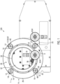
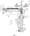
- the forming device 100 comprises forming tools 8, shown only schematically, for producing an outer shape of the glass container 2, a guide tube 10 and a tool changing device 1, the tool changing device 1 being arranged at least in sections along an axial direction A between the guide tube 10 and the forming tools 8.
- the glass container 2 is a glass container with a small diameter, for example a diameter of less than 5 cm. A length of the glass container is at most 20 cm.
- the glass containers 2 are containers for medical products, such as vaccines or medicines, for cosmetic products and/or for food.
- the shaping device is designed for shaping a syringe 4 , in particular its syringe cone 6 .
- the tool changing device 1 allows a quick exchange of a tool 12 for shaping an inner shape of the glass container 2. Consequently, the tool changing device 1 can avoid long downtimes and the production loss associated therewith.
- the tool changing device 1 has at least two tool holder receptacles 14 for receiving a respective tool holder 16 , the at least two tool holder receptacles 14 being movable from at least one loading and unloading position 18 into an operating position 20 . If one of the at least two tool holder receptacles 14 is in the operating position 20, then there is another of the at least two tool holder receptacles 14 in at least one of the loading and unloading positions 18.
- the respective tool holder receptacles 14 each have a through-opening 22, as shown in FIGS Figures 2 to 5 can be seen, for inserting the guide tube 10 provided.
- a tool holder 16 having a tool 12 for forming the interior shape of the glass container 2 can be moved to the operative position 20 while another tool holder 16 is simultaneously moved to a loading and unloading position 18 .
- a particularly compact design of the tool changing device 1 can be achieved by a tool turret 24 which can be rotated in a direction of rotation D about the axial direction A and on which the at least two tool holder receptacles 14 are arranged.
- the tool turret 24 of the tool changing device 1 has a magazine ring 26 designed as a carrier for the at least two tool holder receptacles 14 .
- four tool holder receptacles 14 can be arranged on the magazine ring 26 at a distance from one another in the direction of rotation D.
- a different number of tool holder receptacles 14, for example eight or twelve, can be provided.
- the tool holder receptacles 14 are preferably distributed equigonally, i.e. at equal angular widths, spaced apart from one another in the direction of rotation D on the magazine ring 26.
- the magazine ring 26 can, in particular, be designed to be essentially planar, with the tool holder receptacles 14 being able to be designed as countersinks on a flat side 28 of the magazine ring 26 .
- each tool holder receptacle 14 can be arranged beyond the operating position 20 in a loading and unloading position 18 .
- only one loading and unloading position 18 can be provided, which is preferably arranged diametrically to the operating position 20 .
- Loading and unloading positions 18 can also be separated from one another. For example, in a position following the operating position 20 in the direction of rotation, the tool holder can be removed and in a position following in the direction of rotation D, the tool holder receptacle 14 can be equipped with a tool holder 16 .
- the magazine ring 26 can be designed so that it can be driven in the direction of rotation D in particular.
- the magazine ring 26 of the tool turret 24 can be held by a central ball bearing 30, the ball bearing 30 in turn being held on a base plate 32 with which the tool changing device 1 is attached to the rest of the mold device 100.
- the magazine ring 26 may be provided with an internal toothing 34 which is driven by a drive 38 via a pinion 36 .
- the tool holder receptacles 14 are provided with a coding element 40.
- the coding element 40 can ensure that the tool holder 16 can only be inserted into the tool holder receptacle 14 in a predetermined rotational position relative to the tool holder receptacle 14, or that the tool holder 16 inserted into the tool holder receptacle 14 does not rotate relative to the tool holder receptacle 14. This can be achieved, for example, by the tool holder receptacle 14 not being rotationally symmetrical and the tool holder 16 being designed to complement the tool holder receptacle 14 .
- the located in the operating position 20 tool holder receptacle 14, as best in the Figures 2 to 4 can be seen to be arranged in the axial direction A between the forming tools 8 and the guide tube 10 .
- the push-through opening 22 can be arranged essentially concentrically with the guide tube 10 .
- a tool holder 16 can be used in each tool holder receptacle 14 .
- the tool holder 16 has a shank 42 with a receptacle 44 for one end 46 of the guide tube 10 and a holder 48 opposite the receptacle for exchangeable attachment of the tool 12 .
- the receptacle 44 can be open in the direction of the guide tube 10 in particular.
- the shank 42 of the tool holder 16 can protrude through the insertion opening 22 of the tool holder receptacle 14 when the tool holder 16 is inserted in the tool holder receptacle 14.
- the tool holder 16 can have a head 50 that protrudes radially from the shank 42 and has a bearing surface 52 for axial bearing on a mating surface 54 of the tool holder receptacle 14 that frames the insertion opening 22 .
- the holder 48 for the tool 12 can preferably be arranged on the head 50 .
- the holder 48 is provided with an opening 56 for the tool 12 .
- the tool 12 can thus be inserted into the opening 56 and fixed laterally, for example by a stud (not shown).
- a tool 12 of substantially identical construction can be fixed in each tool holder 16 .
- the opening 56 of the holder 48 is arranged essentially concentrically with the receptacle 44 .
- the concentric arrangement of the holder 48 and the receptacle 44 allows the tool 12 to be aligned over the guide tube 10 . Therefore, a high exchange accuracy in terms of the concentricity between the tool 12 and the glass container 2 can be ensured.
- a clearance is preferably provided in the radial direction between the tool holder 16 and the tool holder receptacle 14, as a result of which the insertion and removal of the tool holder 16 is simplified. Accordingly, the tool holder can be loosely inserted in the respective tool holder receptacle 14 .
- the tool holder 16 and the tool holder receptacle 14 can be designed in such a way that the tool holder 16 is held in the tool holder receptacle 14 mainly or even only by gravity.
- the tool 12 for shaping the inner shape of the glass container 2 is fastened in the holder 48 in an exchangeable manner.
- the tool 12 is a mandrel 58, through which an inner diameter and an inner contour of the glass container 2, in particular a cone of the glass container 2, can be shaped. If, for example, as shown in the figures, a syringe cone 6 is to be shaped, the tool 12 can be a shaped wire 62 .
- the wire-shaped tool makes it possible to form an inner channel with a diameter of a few millimeters, preferably 0.2-3 mm.
- Tool 12 should be heat resistant.
- Tool 12 may preferably be formed from a metal or metal alloy.
- the tool can have tungsten, which means that it is still relatively wear-resistant, particularly at the high temperatures that prevail.
- the tool holder 16 in the operating position 20 can be lifted out of the tool holder receptacle 14 by the guide tube 10, so that the tool 12 is inserted into the glass container 2 and is arranged essentially perpendicularly to the axial direction in the center between two forming rollers 64 serving as forming tools 8 is.
- the guide tube 10 is held movably in the axial direction A through the push-through opening 22 .
- the guide tube 10 can be moved freely between a release position 66, in which the guide tube 10 is arranged on one side of the tool changing device 1 and the tool changing device 1 (see 2 ), and a working position 68, in which the guide tube 10 protrudes through the insertion opening 22 of the tool holder receptacle 14 positioned in the operating position 20 and lifts the tool holder 16 out of the tool holder receptacle 14.
- the guide tube 10 is moved up and down in the axial direction A by a lifting motor 80 via a block 70, a screw 72, a lug 74, a bushing 76 and a lever 78.
- the guide tube 10 can preferably be rigidly connected to the tool holder 16 at least in the working position 68, so that a relative movement of the tool holder 16 to the guide tube 10 during the shaping process can be ruled out. Consequently, malfunctions of the forming device 100, for example due to incorrect positioning of the tool 12 relative to the glass container 2 to be processed, can be avoided.
- the guide tube 10 can be moved into a coupling position 82 located between the release position 66 and the working position 68 (see 3 ), in which the guide tube 10, in particular the end 46 of the guide tube 10, is inserted into the receptacle 44 of the tool holder 16 and is coupled to the tool holder 16.
- the tool holder and guide tube can form a coupling arrangement.
- the guide tube 10 can be provided with a centering clamp 84 at its end 46 facing the tool changing device 44-1.
- the centering clamp 84 ensures an automatic concentric arrangement of the tool holder 16 and the guide tube 10 during the coupling. Consequently, when inserting the tool holder 16 into the tool holder receptacle 14, it is no longer necessary to ensure that the tool holder 16 is positioned precisely in the tool holder receptacle 14. Accordingly, the effort involved in inserting the tool holder 16 into the tool holder receptacle 14 is reduced, while at the same time a high degree of accuracy in changing the tool 12 with regard to concentricity is achieved.
- the orientation of the tool 12 in the working position 68 be determined via the guide tube 10 .
- a quick coupling that centers the tool holder with respect to the guide tube 10 can thus be achieved by the centering clamp 84 which forms the end 46 .
- the centering clamp 84 consists of an upper cone 86, a lower cone 88 and centering balls 90 arranged between the upper cone 86 and the lower cone 88.
- the upper cone 86 can be moved relative to the lower cone via a tie rod 92 and a tie rod 96 mounted on a compression spring 94 88 held.
- the compression spring 94 presses the upper cone 86 via the tie rod 96 and the tie rod 92 downwards in the axial direction A to the lower cone 88, causing the centering balls 90 evenly outwards and at the same time diagonally downwards be pressed.
- the centering balls 90 press into recesses 99 spaced apart from one another in the circumferential direction on a radially inward-pointing wall 98 of the receptacle 44 in such a way that the tool holder 14 is both positioned centrally and is pressed downwards in the axial direction A toward the guide tube.
- a lower end face 102 of the tool holder 16 lies on an upper end face 104 of the guide tube 10.
- the positive connection created in the axial direction A by the centering balls 90 and the non-positive connection to the face contact in the depressions 99 result in a very high changeover accuracy both in terms of concentricity as well as in terms of axial positioning accuracy.
- a piston 106 of a pneumatic cylinder 108 moves upwards in axial direction A and pushes the upper cone 86 upwards in axial direction A away from the lower cone 88 via a push rod 110, the tie rod 96 and the tie rod 92, whereby move the centering balls 90 radially inwards again.
- the centering balls 90 are pulled inwards by an annular spring (not shown).
- a clear width 112 of the receptacle of the tool holder 16 can be oversized compared to the centering clamp 84 in the relaxed state. If the clear width of the holder is, for example, 2 mm larger than the outside diameter of the centering vice in the relaxed state, the tool holder can be up to 1 mm off-centre in the tool holder holder without colliding with the centering vice.
- the centering balls press against the inner wall of the receptacle pointing radially inwards and aligns the tool holder concentrically with the centering clamp and thus also with the guide tube.
- a tool change can take place during operation, as described below.
- the tool holder located in the operating position 20 is lifted out of the tool holder receptacle 16 by the guide tube 10 (see FIG 4 ).
- the tool 12 fastened in the holder 48 can be inserted in the glass container 2, so that when the forming rollers 64 press against the cone of the glass container from the outside, the inner shape of the cone is formed via the tool 12 .
- the magazine ring 26 is then rotated further by one rotational position in the direction of rotation D, so that at the same time a tool holder receptacle 16 is moved into the operating position 20 and another tool holder receptacle 16 is moved into the loading and unloading position 18 .
- the previously stressed tool can now be changed at leisure without switching off the mold device or stopping the molding process.
- the tool can be changed cyclically or by manual intervention.
- a sensor unit can be provided which continuously checks the condition of the tool. In the event of a premature failure of the tool 12, for example due to breaking off or excessive wear, an early tool change can be initiated.
- the tool 12 can preferably be checked by an optical sensor, for example by a laser light barrier.
Landscapes
- Chemical & Material Sciences (AREA)
- Engineering & Computer Science (AREA)
- Materials Engineering (AREA)
- Organic Chemistry (AREA)
- Manufacturing & Machinery (AREA)
- Re-Forming, After-Treatment, Cutting And Transporting Of Glass Products (AREA)
Applications Claiming Priority (1)
| Application Number | Priority Date | Filing Date | Title |
|---|---|---|---|
| DE102021133547.7A DE102021133547A1 (de) | 2021-12-16 | 2021-12-16 | Werkzeugwechselvorrichtung für eine Formeinrichtung zur Formgebung von Glasbehältern |
Publications (1)
| Publication Number | Publication Date |
|---|---|
| EP4206152A1 true EP4206152A1 (fr) | 2023-07-05 |
Family
ID=84535890
Family Applications (1)
| Application Number | Title | Priority Date | Filing Date |
|---|---|---|---|
| EP22213456.1A Pending EP4206152A1 (fr) | 2021-12-16 | 2022-12-14 | Dispositif de changement d'outil pour un dispositif de formage de récipients en verre |
Country Status (2)
| Country | Link |
|---|---|
| EP (1) | EP4206152A1 (fr) |
| DE (1) | DE102021133547A1 (fr) |
Citations (5)
| Publication number | Priority date | Publication date | Assignee | Title |
|---|---|---|---|---|
| US3437471A (en) * | 1966-03-30 | 1969-04-08 | American Cyanamid Co | Compact ampule sealer |
| CH644334A5 (it) * | 1979-11-27 | 1984-07-31 | Ermanno Vertova | Procedimento e macchina per la formazione di fiale ottenute da tubo di vetro. |
| EP1754688A1 (fr) * | 2005-08-17 | 2007-02-21 | AMBEG Dr. J. Dichter GmbH | Procédé et dispositif pour la fabrication des corps de seringue |
| EP1725501B1 (fr) * | 2004-03-17 | 2008-05-28 | AMBEG Dr. J. Dichter GmbH | Machine de faconnage du verre |
| US20190161381A1 (en) * | 2017-11-30 | 2019-05-30 | Corning Incorporated | Systems and methods for minimizing shr from pharmaceutical part converting using pulsed ejection |
Family Cites Families (2)
| Publication number | Priority date | Publication date | Assignee | Title |
|---|---|---|---|---|
| DE3405291C2 (de) | 1984-02-15 | 1993-03-25 | Owens-Illinois, Inc., Toledo, Ohio | Maschine zum Endenbearbeiten von benachbarten Bereichen von Glasformlingen |
| DE102012101581A1 (de) | 2012-02-27 | 2013-08-29 | Optotech Optikmaschinen Gmbh | Vorrichtung und Verfahren zur Bearbeitung von Brillenglasrohlingen |
-
2021
- 2021-12-16 DE DE102021133547.7A patent/DE102021133547A1/de active Pending
-
2022
- 2022-12-14 EP EP22213456.1A patent/EP4206152A1/fr active Pending
Patent Citations (5)
| Publication number | Priority date | Publication date | Assignee | Title |
|---|---|---|---|---|
| US3437471A (en) * | 1966-03-30 | 1969-04-08 | American Cyanamid Co | Compact ampule sealer |
| CH644334A5 (it) * | 1979-11-27 | 1984-07-31 | Ermanno Vertova | Procedimento e macchina per la formazione di fiale ottenute da tubo di vetro. |
| EP1725501B1 (fr) * | 2004-03-17 | 2008-05-28 | AMBEG Dr. J. Dichter GmbH | Machine de faconnage du verre |
| EP1754688A1 (fr) * | 2005-08-17 | 2007-02-21 | AMBEG Dr. J. Dichter GmbH | Procédé et dispositif pour la fabrication des corps de seringue |
| US20190161381A1 (en) * | 2017-11-30 | 2019-05-30 | Corning Incorporated | Systems and methods for minimizing shr from pharmaceutical part converting using pulsed ejection |
Also Published As
| Publication number | Publication date |
|---|---|
| DE102021133547A1 (de) | 2023-06-22 |
Similar Documents
| Publication | Publication Date | Title |
|---|---|---|
| EP0116111B1 (fr) | Machine pour le travail hydroplastique de pièces tubulaires | |
| EP3359316B1 (fr) | Presse à vis et procédé pour l'usinage de pièces par mise en forme | |
| DE3879484T2 (de) | Vorrichtung zur herstellung eines gleichlaufdrehgelenks. | |
| DE4315839C2 (de) | Werkstückspannvorrichtung für Mehrseitenbearbeitung | |
| EP3180139B1 (fr) | Outil multiple | |
| DE4143373C2 (de) | Aufnahmeeinrichtung für ein abnehmbares Werkzeugteil einer Werkzeugeinheit | |
| DE2830150C2 (de) | Vorrichtung zum Herstellen von Formkörpern aus thermoplastischem Kunststoff | |
| DE1919269B1 (de) | Siebwechseleinrichtung fuer einen Extruder | |
| EP3650213B1 (fr) | Presse à comprimés et procédé de fabrication d'un comprimé | |
| DE60113739T3 (de) | Glascontainerplungervorrichtung | |
| DE3327258C2 (fr) | ||
| EP0739663A2 (fr) | Machine pour former des pièces | |
| EP1074320B1 (fr) | Machine de poinçonnage et d'estampage | |
| DE1552182C3 (de) | Vorrichtung zum Radialpressen von Verzahnungen | |
| EP0328958B1 (fr) | Dispositif d'usinage de surfaces de pièces à symétrie de révolution | |
| DE2302761C3 (de) | Einrichtung zum Abziehen der einzelnen Abschnitte einer geteilten Gießform | |
| EP4206152A1 (fr) | Dispositif de changement d'outil pour un dispositif de formage de récipients en verre | |
| DE3917507C2 (de) | Einrichtung zum automatischen Wechseln von Werkzeugen zum Herstellen von Blindnietverbindungen | |
| DE3686744T2 (de) | Spritzstreckblasformmaschine. | |
| EP4355511B1 (fr) | Procédé et dispositif de formage pour la fabrication de pièces moulées annulaires | |
| EP0732193B1 (fr) | Dispositif de fixation des matrices dans la table d'une machine de fabrication de comprimés | |
| DE629150C (de) | Maschine zum Herstellen von Glashohlkoerpern, insbesondere Ampullen, aus Glasrohren | |
| DE10144834A1 (de) | Vorrichtung zur Herstellung eines eine konzentrische Nabe aufweisenden Formkörpers | |
| DE2942001A1 (de) | Maschine zum herstellen von schrauben o.dgl. | |
| DE202009008413U1 (de) | Werkzeugsystem für eine Umformpresse |
Legal Events
| Date | Code | Title | Description |
|---|---|---|---|
| PUAI | Public reference made under article 153(3) epc to a published international application that has entered the european phase |
Free format text: ORIGINAL CODE: 0009012 |
|
| STAA | Information on the status of an ep patent application or granted ep patent |
Free format text: STATUS: THE APPLICATION HAS BEEN PUBLISHED |
|
| AK | Designated contracting states |
Kind code of ref document: A1 Designated state(s): AL AT BE BG CH CY CZ DE DK EE ES FI FR GB GR HR HU IE IS IT LI LT LU LV MC ME MK MT NL NO PL PT RO RS SE SI SK SM TR |
|
| STAA | Information on the status of an ep patent application or granted ep patent |
Free format text: STATUS: REQUEST FOR EXAMINATION WAS MADE |
|
| 17P | Request for examination filed |
Effective date: 20240104 |
|
| RBV | Designated contracting states (corrected) |
Designated state(s): AL AT BE BG CH CY CZ DE DK EE ES FI FR GB GR HR HU IE IS IT LI LT LU LV MC ME MK MT NL NO PL PT RO RS SE SI SK SM TR |