EP4206453A1 - Démarrage de moteurs à turbine à gaz - Google Patents
Démarrage de moteurs à turbine à gaz Download PDFInfo
- Publication number
- EP4206453A1 EP4206453A1 EP22208020.2A EP22208020A EP4206453A1 EP 4206453 A1 EP4206453 A1 EP 4206453A1 EP 22208020 A EP22208020 A EP 22208020A EP 4206453 A1 EP4206453 A1 EP 4206453A1
- Authority
- EP
- European Patent Office
- Prior art keywords
- gas turbine
- turbine engine
- engine
- electric machines
- power
- Prior art date
- Legal status (The legal status is an assumption and is not a legal conclusion. Google has not performed a legal analysis and makes no representation as to the accuracy of the status listed.)
- Withdrawn
Links
Images


Classifications
-
- F—MECHANICAL ENGINEERING; LIGHTING; HEATING; WEAPONS; BLASTING
- F02—COMBUSTION ENGINES; HOT-GAS OR COMBUSTION-PRODUCT ENGINE PLANTS
- F02C—GAS-TURBINE PLANTS; AIR INTAKES FOR JET-PROPULSION PLANTS; CONTROLLING FUEL SUPPLY IN AIR-BREATHING JET-PROPULSION PLANTS
- F02C7/00—Features, components parts, details or accessories, not provided for in, or of interest apart form groups F02C1/00 - F02C6/00; Air intakes for jet-propulsion plants
- F02C7/26—Starting; Ignition
- F02C7/268—Starting drives for the rotor, acting directly on the rotor of the gas turbine to be started
-
- B—PERFORMING OPERATIONS; TRANSPORTING
- B64—AIRCRAFT; AVIATION; COSMONAUTICS
- B64D—EQUIPMENT FOR FITTING IN OR TO AIRCRAFT; FLIGHT SUITS; PARACHUTES; ARRANGEMENT OR MOUNTING OF POWER PLANTS OR PROPULSION TRANSMISSIONS IN AIRCRAFT
- B64D27/00—Arrangement or mounting of power plants in aircraft; Aircraft characterised by the type or position of power plants
- B64D27/02—Aircraft characterised by the type or position of power plants
- B64D27/30—Aircraft characterised by electric power plants
- B64D27/33—Hybrid electric aircraft
-
- B—PERFORMING OPERATIONS; TRANSPORTING
- B64—AIRCRAFT; AVIATION; COSMONAUTICS
- B64D—EQUIPMENT FOR FITTING IN OR TO AIRCRAFT; FLIGHT SUITS; PARACHUTES; ARRANGEMENT OR MOUNTING OF POWER PLANTS OR PROPULSION TRANSMISSIONS IN AIRCRAFT
- B64D31/00—Power plant control systems; Arrangement of power plant control systems in aircraft
- B64D31/02—Initiating means
-
- B—PERFORMING OPERATIONS; TRANSPORTING
- B64—AIRCRAFT; AVIATION; COSMONAUTICS
- B64D—EQUIPMENT FOR FITTING IN OR TO AIRCRAFT; FLIGHT SUITS; PARACHUTES; ARRANGEMENT OR MOUNTING OF POWER PLANTS OR PROPULSION TRANSMISSIONS IN AIRCRAFT
- B64D31/00—Power plant control systems; Arrangement of power plant control systems in aircraft
- B64D31/02—Initiating means
- B64D31/06—Initiating means actuated automatically
-
- B—PERFORMING OPERATIONS; TRANSPORTING
- B64—AIRCRAFT; AVIATION; COSMONAUTICS
- B64D—EQUIPMENT FOR FITTING IN OR TO AIRCRAFT; FLIGHT SUITS; PARACHUTES; ARRANGEMENT OR MOUNTING OF POWER PLANTS OR PROPULSION TRANSMISSIONS IN AIRCRAFT
- B64D31/00—Power plant control systems; Arrangement of power plant control systems in aircraft
- B64D31/16—Power plant control systems; Arrangement of power plant control systems in aircraft for electric power plants
- B64D31/18—Power plant control systems; Arrangement of power plant control systems in aircraft for electric power plants for hybrid-electric power plants
-
- B—PERFORMING OPERATIONS; TRANSPORTING
- B64—AIRCRAFT; AVIATION; COSMONAUTICS
- B64D—EQUIPMENT FOR FITTING IN OR TO AIRCRAFT; FLIGHT SUITS; PARACHUTES; ARRANGEMENT OR MOUNTING OF POWER PLANTS OR PROPULSION TRANSMISSIONS IN AIRCRAFT
- B64D35/00—Transmitting power from power plants to propellers or rotors; Arrangements of transmissions
- B64D35/08—Transmitting power from power plants to propellers or rotors; Arrangements of transmissions characterised by the transmission being driven by a plurality of power plants
-
- F—MECHANICAL ENGINEERING; LIGHTING; HEATING; WEAPONS; BLASTING
- F02—COMBUSTION ENGINES; HOT-GAS OR COMBUSTION-PRODUCT ENGINE PLANTS
- F02K—JET-PROPULSION PLANTS
- F02K5/00—Plants including an engine, other than a gas turbine, driving a compressor or a ducted fan
-
- B—PERFORMING OPERATIONS; TRANSPORTING
- B64—AIRCRAFT; AVIATION; COSMONAUTICS
- B64D—EQUIPMENT FOR FITTING IN OR TO AIRCRAFT; FLIGHT SUITS; PARACHUTES; ARRANGEMENT OR MOUNTING OF POWER PLANTS OR PROPULSION TRANSMISSIONS IN AIRCRAFT
- B64D41/00—Power installations for auxiliary purposes
- B64D2041/002—Mounting arrangements for auxiliary power units (APU's)
-
- B—PERFORMING OPERATIONS; TRANSPORTING
- B64—AIRCRAFT; AVIATION; COSMONAUTICS
- B64D—EQUIPMENT FOR FITTING IN OR TO AIRCRAFT; FLIGHT SUITS; PARACHUTES; ARRANGEMENT OR MOUNTING OF POWER PLANTS OR PROPULSION TRANSMISSIONS IN AIRCRAFT
- B64D2221/00—Electric power distribution systems onboard aircraft
-
- F—MECHANICAL ENGINEERING; LIGHTING; HEATING; WEAPONS; BLASTING
- F01—MACHINES OR ENGINES IN GENERAL; ENGINE PLANTS IN GENERAL; STEAM ENGINES
- F01D—NON-POSITIVE DISPLACEMENT MACHINES OR ENGINES, e.g. STEAM TURBINES
- F01D15/00—Adaptations of machines or engines for special use; Combinations of engines with devices driven thereby
- F01D15/10—Adaptations for driving, or combinations with, electric generators
-
- F—MECHANICAL ENGINEERING; LIGHTING; HEATING; WEAPONS; BLASTING
- F02—COMBUSTION ENGINES; HOT-GAS OR COMBUSTION-PRODUCT ENGINE PLANTS
- F02C—GAS-TURBINE PLANTS; AIR INTAKES FOR JET-PROPULSION PLANTS; CONTROLLING FUEL SUPPLY IN AIR-BREATHING JET-PROPULSION PLANTS
- F02C6/00—Plural gas-turbine plants; Combinations of gas-turbine plants with other apparatus; Adaptations of gas-turbine plants for special use
- F02C6/14—Gas-turbine plants having means for storing energy, e.g. for meeting peak loads
-
- F—MECHANICAL ENGINEERING; LIGHTING; HEATING; WEAPONS; BLASTING
- F05—INDEXING SCHEMES RELATING TO ENGINES OR PUMPS IN VARIOUS SUBCLASSES OF CLASSES F01-F04
- F05D—INDEXING SCHEME FOR ASPECTS RELATING TO NON-POSITIVE-DISPLACEMENT MACHINES OR ENGINES, GAS-TURBINES OR JET-PROPULSION PLANTS
- F05D2220/00—Application
- F05D2220/30—Application in turbines
- F05D2220/32—Application in turbines in gas turbines
- F05D2220/323—Application in turbines in gas turbines for aircraft propulsion, e.g. jet engines
-
- F—MECHANICAL ENGINEERING; LIGHTING; HEATING; WEAPONS; BLASTING
- F05—INDEXING SCHEMES RELATING TO ENGINES OR PUMPS IN VARIOUS SUBCLASSES OF CLASSES F01-F04
- F05D—INDEXING SCHEME FOR ASPECTS RELATING TO NON-POSITIVE-DISPLACEMENT MACHINES OR ENGINES, GAS-TURBINES OR JET-PROPULSION PLANTS
- F05D2220/00—Application
- F05D2220/70—Application in combination with
- F05D2220/76—Application in combination with an electrical generator
-
- F—MECHANICAL ENGINEERING; LIGHTING; HEATING; WEAPONS; BLASTING
- F05—INDEXING SCHEMES RELATING TO ENGINES OR PUMPS IN VARIOUS SUBCLASSES OF CLASSES F01-F04
- F05D—INDEXING SCHEME FOR ASPECTS RELATING TO NON-POSITIVE-DISPLACEMENT MACHINES OR ENGINES, GAS-TURBINES OR JET-PROPULSION PLANTS
- F05D2260/00—Function
- F05D2260/85—Starting
-
- Y—GENERAL TAGGING OF NEW TECHNOLOGICAL DEVELOPMENTS; GENERAL TAGGING OF CROSS-SECTIONAL TECHNOLOGIES SPANNING OVER SEVERAL SECTIONS OF THE IPC; TECHNICAL SUBJECTS COVERED BY FORMER USPC CROSS-REFERENCE ART COLLECTIONS [XRACs] AND DIGESTS
- Y02—TECHNOLOGIES OR APPLICATIONS FOR MITIGATION OR ADAPTATION AGAINST CLIMATE CHANGE
- Y02T—CLIMATE CHANGE MITIGATION TECHNOLOGIES RELATED TO TRANSPORTATION
- Y02T50/00—Aeronautics or air transport
- Y02T50/60—Efficient propulsion technologies, e.g. for aircraft
Definitions
- This disclosure concerns the starting of propulsive gas turbine engines of multi-engine aircraft.
- the start-up procedure comprises: supplying electrical power from an electrical power source to one or more of the electric machines of the first gas turbine engine and operating said one or more electric machines as motors to drive rotation of one or more spools of the first gas turbine engine; starting the first gas turbine engine by lighting the combustion equipment of the first gas turbine engine; operating one or more of the electric machines of the first gas turbine engine as generators to extract mechanical power and generate electrical power from one or more of the spools of the first gas turbine engine; transferring, via the electrical system, electrical power generated by the one or more electric machines of the first gas turbine engine to one or more of the electric machines of the second gas turbine engine and operating said one or more electric machines as motors to drive rotation of one or more spools of the second gas turbine engine; and starting the second gas turbine engine by lighting the combustion equipment of the second gas turbine engine.
- the second engine can be started using power generated by the first engine after the first engine has been started. This can reduce or even eliminate the need to use a ground cart or APU to start the engines.
- the aircraft includes energy storage sufficient to electrically start the first engine (that is, the electrical power source is on-board energy storage such as a battery, supercapacitor, fuel cell or a combination thereof)
- the APU may - optionally - be entirely omitted from the aircraft. Removing the APU would reduce the mass of the aircraft, which would reduce the fuel consumption of the engines. Eliminating the need for ground carts would reduce the need for airports to keep and maintain the carts, and possibly reduce turnaround times between flights.
- the electrical power source takes the form of energy storage for the aforementioned reasons, it will be understood that the electrical power source could also be an APU of the aircraft, or a ground-based power source such as a ground cart could be used. Either of these could also be used in combination with power from on-board energy storage.
- the energy storage system may have a high energy storage capacity relative to the platform power.
- a ratio defined as a total energy storage capacity of the electrical energy storage system divided by: a combined maximum rated thrust of the first and second propulsive gas turbine engines may be greater than or equal to 0.1 WhN -1 .
- the ratio may be between 0.15 and 0.50 WhN -1 .
- the ratio is between 0.18 and 0.45 WhN -1 .
- the ratio is between 0.18 and 0.28 WhN -1 .
- the ratio is between 0.25 and 0.42 WhN -1 .
- the electrical system may comprise a dc electrical power distribution system, with the electrical power that is transferred from the first engine to the second engine being transferred in dc form over the dc electrical distribution system.
- Aircraft conventionally utilize an ac distribution system, partly because the use of ac has advantages in terms of lower cost and weight due to a reduced need for power electronics converters.
- a dc distribution system provides significant advantages in terms of cross-engine electric starting. This is because the use of an ac distribution system necessitates that all electrical generators providing power to the ac system output their power at the same frequency.
- each of the spools will rotate at a different speed at essentially any engine operating point.
- variable frequency drives associated with the electric machines may be used to provide ac outputs at a common, preferably constant, ac frequency despite the different operating speeds of the associated spools, this may in practice be difficult to implement with an acceptable level of power quality.
- This may in practice mean that the use of an ac system limits the amount of power which can be transferred to the second engine to the amount of power which can be extracted from a single engine spool.
- the amount of power available from one spool can be significant at some engine operating points, for example maximum take-off. However, it would be undesirable to power the first engine up to maximum take-off in order to start the second engine, partly because this would burn a significant amount of fuel.
- the amount of power available from one spool of the first engine is much smaller, and in many cases may not be enough to start the second engine. Whilst the deficit could be made up using energy storage, this could create the need to charge the energy storage between the starting of the first engine and the starting the second engine (if energy storage was used to start the first engine), creating a delay in starting the second engine. Alternatively, it could create the need for a larger amount of energy storage, which could add a significant amount of weight.
- power can be sourced from multiple spools of a multi-spool engine, allowing the second engine to be started using power generated from the first engine even at lower-power conditions such as ground idle.
- starting the second gas turbine engine using only electrical power generated by the one or more electric machines of the first gas turbine engine may reduce a required size of the energy storage system and/or eliminate the need to recharge the energy storage system between the starting of the first and second engines.
- the energy storage system may be at least partially recharged between the starting of the first and second engines using electrical power generated by the one or more electric machines of the first engine.
- the second engine may be started at even lower power conditions of the first engine, which can for example reduce noise associated with the engine start procedure.
- Each of the first and second gas turbine engines may comprise a first spool and a second spool.
- Each of the first and second gas turbine engines may comprise a first electric machine mechanically coupled with its first spool, and a second electric machine mechanically coupled with its second spool.
- Operating the one or more of the electric machines of the first gas turbine engine as generators may comprise: operating both the first electric machine and the second electric machine of the first gas turbine engine as generators to extract mechanical power and generate electrical power from both the first spool and the second spool of the first gas turbine engine.
- Transferring electrical power generated by the one or more electric machines of the first gas turbine engine to one or more of the electric machines of the second gas turbine engine, and operating said one or more electric machines as motors to drive rotation of one or more spools of the second gas turbine engine may comprise: transferring the electrical power generated from both the first and second spool of the first gas turbine engine to one or both of the first electric machine of the second gas turbine engine and/or the second electric machine of the second gas turbine engine, and operating said one or both of the first and/or second electric machine of the second gas turbine engine as motors to drive rotation of the first and/or second spool of the second gas turbine engine.
- power may be extracted from multiple spools of the first engine, it may be transferred to only the electric machine of one spool of the second engine.
- This may be the designated 'starting spool' of the engine, which is typically the high pressure (HP) spool though this is not necessarily the case (e.g. the intermediate pressure (IP) spool of a three-spool engine could be used).
- power is delivered to the machines of multiple spools of the second engine.
- the electrical system may further comprise: a first ac-dc converter connecting the first electric machine of the first gas turbine engine to the dc power distribution system; a second ac-dc converter connecting the second electric machine of the first gas turbine engine to the dc power distribution system; a third ac-dc converter connecting the first electric machine of the second gas turbine engine to a dc power distribution system; and a fourth ac-dc converter connecting the second electric machine of the second gas turbine engine to a dc distribution system.
- the use of dedicated power converters for each electric machine may improve the flexibility and operability of the system.
- the dc electrical power distribution system may comprise: a first dc distribution bus connected with dc sides of the first and second ac-dc converters; a second dc distribution bus connected with dc sides of the third and fourth ac-dc converters; and a bus tie operable to connect together the first and second dc distribution busses, whereby electrical power generated by the first and/or second electric machine of the first gas turbine engine can be transferred to the first and/or second electric machine of the second gas turbine engine.
- the first and second engines may have functionally independent electric distribution systems which are capable of connection for the purposes of cross-starting, and possibly also management of faults or failure in the engines and/or electrical system.
- the first electric machine may comprise a first sub-machine and a second sub-machine; and the second electric machine may comprise a first sub-machine and a second sub-machine.
- sub-machine of an electric machine will be understood by those skilled in the art to refer to one of a plurality of functionally separate electric machines which share some common structure.
- each sub-machine is capable of generating separate electrical power or torque (depending on the mode of the operation, i.e. generator mode or motor mode), but each one of the plurality of sub-machines is not totally physically independent from the other sub-machines and thus all of the sub-machines must be deployed together.
- two sub-machines of an electric machine may share a common rotor but have completely independent stators; they may some common stator structure (e.g.
- an electric machine with two sub-machines may be considered to be an integrated arrangement of two functionally separate electric machines.
- the second engine may be started using electrical power generated from the first engine even in the presence of a fault or failure of a phase, or even entire sub-machine, of a machine in the first engine.
- the electrical system may further comprise: a first set of ac-dc converters connecting the first and second sub-machines of the first electric machine of the first gas turbine engine to the dc power distribution system; a second set of ac-dc converter connecting the first and second sub-machines of the second electric machine of the first gas turbine engine to the dc power distribution system; a third set of ac-dc converters connecting the first and second sub-machines of the first electric machine of the second gas turbine engine to a dc power distribution system; and a fourth set of ac-dc converters connecting the first and second sub-machines of the second electric machine of the second gas turbine engine to a dc distribution system.
- a ratio, P 1 /T equal to the maximum electrical power generation rating of the first electric machine divided by the maximum thrust rating of the gas turbine engine, may be greater than or equal to 2.0 WN -1 .
- the thrust rating is a dry thrust rating (i.e. without the use of reheat/afterburner, if such a system is present in the engine).
- the first spool may be an intermediate pressure (IP) spool of the gas turbine engine.
- IP intermediate pressure
- intermediate pressure spool will be understood to refer to a spool which is neither the highest pressure nor the lowest pressure spool of the engine. In other embodiments, the first spool is a low pressure (LP) spool of the gas turbine engine.
- the value of the ratio, P 1 /T may be greater than 2.5 WN -1 , greater than 3.0 WN -1 , or even greater than 3.5 WN -1 .
- the value of the ratio, P 1 /T may be less than 7.0 WN -1 , less than 6.5 WN -1 , less than 6.0 WN -1 , or less than 5.5 WN -1 .
- the value of the ratio, P 1 /T may be between 2.5 WN -1 and 6.0 WN -1 or between 3.0 WN -1 and 5.5 WN -1 . In one embodiment the value of the ratio, P 1 /T, is between 3.5 WN -1 and 5.0 WN -1 .
- a ratio, P 2 /T equal to the maximum electrical power generation rating of the second electric machine divided by the maximum thrust rating of the gas turbine engine, may be greater than or equal to 3.5 WN -1 .
- the thrust rating is a dry thrust rating (i.e. without the use of reheat/afterburner, if such a system is present in the engine).
- the second spool may be a high pressure (HP) spool of the gas turbine engine.
- HP high pressure
- the term "high pressure spool” will be understood to refer to the highest pressure spool of the engine.
- the value of the ratio, P 2 /T may be significantly higher than in conventional gas turbine engines.
- the value of the ratio, P 2 /T may be greater than 4.0 WN -1 , greater than 4.5 WN -1 , greater than 5.0 WN -1 or even greater than 5.5 WN -1 .
- the value of the ratio, P 2 /T may be less than 10.0 WN -1 , less than 9.5 WN -1 , less than 9.0 WN -1 , or less than 8.5 WN -1 .
- the value of the ratio, P 2 /T may be between 4.0 WN -1 and 9.5 WN -1 , between 4.5 WN -1 and 9.0 WN -1 , between 5.0 WN -1 and 8.5 WN -1 or between 5.5 WN -1 and 8.0 WN -1 .
- the value of the ratio, P 2 /T is between 6.0 WN -1 and 7.5 WN -1 .
- the electric machines of the first and second spool are equally rated, e.g. P1/T and P2/T may have equal or substantially equal values greater than or equal to 2.0 WN -1 .
- a ratio defined as the combined rated power of all of the one or more electrical machines mechanically coupled with the one or more spools of the respective gas turbine engine divided by the maximum rated thrust of the respective gas turbine engine may be greater than 4.5 WN -1 .
- the thrust rating is a dry thrust rating (i.e. without the use of reheat/afterburner, if such a system is present in the engine).
- the value of the ratio may be significantly higher than in conventional gas turbine engines, and may be particularly beneficial for allowing cross-engine electric starting over a wide range of engine operating points.
- the ratio may be greater than 5.0 WN -1 , for example greater than 5.5 WN -1 , greater than 6.0 WN -1 , greater than 6.5 WN -1 , greater than 7.0 WN -1 , or even greater than 7.5 WN -1 .
- the ratio may be less than 15.0 WN -1 .
- the ratio is between 5.5 WN -1 and 13 WN -1 , and is preferably between 6.0 WN -1 and 12.5 WN -1 .
- the ratio is between 8.0 WN -1 and 12.0 WN -1 .
- one or more and optionally all of the electric machines may be embedded with a core of the respective gas turbine engine.
- Embedding machines within the engine core such that they are coaxial with and directly driven by the engine spools, may reduce mechanical losses and thus improve the margin for cross-engine electric start.
- each of the propulsive gas turbine engines may be of any suitable type known in the art.
- each engine may be of the ducted fan or turbofan type, or of the unducted or open rotor type.
- control system of the first aspect is provided separately.
- the control system may take the form of a controller or one or more controllers, each of which may be implemented in hardware, software of a combination of the two.
- the control system may comprise one or more functional modules of a wider control system.
- the control system is or is part of an Electronic Engine Controller (EEC), Engine Control Unit (ECU) or Full Authority Digital Engine Controller (FADEC).
- EEC Electronic Engine Controller
- ECU Engine Control Unit
- FADEC Full Authority Digital Engine Controller
- a multi-engine aircraft comprising the power and propulsion system of the first aspect.
- a method of starting propulsive gas turbine engines of a multi-engine aircraft comprises: first and second propulsive gas turbine engines, each comprising combustion equipment; a plurality of spools; and one or more electric machines mechanically coupled with one or more of the plurality spools; and an electrical system electrically connecting one or more electric machines of the first gas turbine and one or more electric machines of the second gas turbine.
- the method comprises: supplying electrical power from an electrical power source to one or more of the electric machines of the first gas turbine engine and operating said one or more electric machines as motors to drive rotation of one or more spools of the first gas turbine engine; starting the first gas turbine engine by lighting the combustion equipment of the first gas turbine engine; operating one or more of the electric machines of the first gas turbine engine as generators to extract mechanical power and generate electrical power from one or more spools of the first gas turbine engine; transferring, via the electrical system, electrical power generated by the one or more electric machines of the first gas turbine engine to one or more electric machines of the second gas turbine engine and operating said one or more electric machines as motors to drive rotation of one or more spools of the second gas turbine engine; and starting the second gas turbine engine by lighting the combustion equipment of the second gas turbine engine.
- Each of the first and second gas turbine engines may comprise a first spool and a second spool; and each of the first and second gas turbine engines may comprise a first electric machine mechanically coupled with its first spool, and a second electric machine mechanically coupled with its second spool.
- Operating one or more electric machines of the first gas turbine engine as motors to drive rotation of one or more spools of the first gas turbine engine may comprise: operating one or both of the first and second electric machines of the first gas turbine engine as motors to drive rotation of the first and/or second spools of the first gas turbine engine.
- Operating one or more of the electric machines of the first gas turbine engine as generators to extract mechanical power and generate electrical power from one or more spools of the first gas turbine engine may comprise: operating both the first and second electric machines of the first gas turbine engine as generators to extract mechanical power and generate electrical power from both the first spool and the second spool of the first gas turbine engine.
- Operating one or more electric machines of the second gas turbine engine as motors to drive rotation of one or more spools of the second gas turbine engine may comprise: operating one or both of the first and second electric machines of the second gas turbine engine as motors to drive rotation of the first and/or second spools of the first gas turbine engine.
- the electrical power source may comprise an energy storage system.
- the method may further comprise: prior to transferring electrical power generated by the one or more electric machines of the first gas turbine engine to one or more electric machines of the second gas turbine engine, charging the energy storage system using electrical power generated the one or more electric machines of the first gas turbine engine; and subsequent to charging the energy storage system and prior to starting the second gas turbine engine by lighting the combustion equipment of the second gas turbine engine, transferring electrical power from the energy storage system to the one or more electric machines of the second gas turbine engine.
- a ratio defined as a peak electrical power generated by the one or more electric machines of the first gas turbine engine and transferred, via the electrical system, to the one or electric machines of the second gas turbine engine during the start-up procedure, divided by the maximum rated thrust of the first gas turbine engine, may be greater than or equal to 2.0 WN -1 .
- the thrust rating is a dry thrust rating ( i.e. without the use of reheat/afterburner, if such a system is present in the engine).
- the ratio is even greater than 2.0 WN -1 , for example greater than or equal to 2.5 WN -1 , or greater than or equal to 3.0 WN -1 .
- the ratio may be less than 5.0 WN -1 , for example between 2.0 WN -1 and 5.0 WN -1 , between 2.5 WN -1 and 4.5 WN -1 , or between 3.0 WN -1 and 4.0 WN -1 .
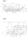
- FIG. 1 illustrates a gas turbine engine 10 having a principal rotational axis 9.
- the engine 10 comprises an air intake 12 and a propulsive fan 23 that generates two airflows: a core airflow A and a bypass airflow B.
- the gas turbine engine 10 comprises a core 11 that receives the core airflow A.
- the engine core 11 comprises, in axial flow series, a low pressure compressor 14, a high-pressure compressor 15, combustion equipment 16, a high-pressure turbine 17, a low pressure turbine 19 and a core exhaust nozzle 20.
- a nacelle 21 surrounds the gas turbine engine 10 and defines a bypass duct 22 and a bypass exhaust nozzle 18.
- the bypass airflow B flows through the bypass duct 22.
- the fan 23 is attached to and driven by the low pressure turbine 19 via a shaft 26 and an epicyclic gearbox 30.
- the core airflow A is accelerated and compressed by the low pressure compressor 14 and directed into the high pressure compressor 15 where further compression takes place.
- the compressed air exhausted from the high pressure compressor 15 is directed into the combustion equipment 16 where it is mixed with fuel and the mixture is combusted.
- the resultant hot combustion products then expand through, and thereby drive, the high pressure and low pressure turbines 17, 19 before being exhausted through the nozzle 20 to provide some propulsive thrust.
- the high pressure turbine 17 drives the high pressure compressor 15 by a suitable interconnecting shaft 27.
- the fan 23 generally provides the majority of the propulsive thrust.
- the epicyclic gearbox 30 is a reduction gearbox.
- the low-pressure compressor 14, the low-pressure turbine 19 and the interconnecting shaft 26 together form the low-pressure spool.
- the high-pressure compressor 15, the high-pressure turbine 17 and the interconnecting shaft 27 together form the high-pressure spool.
- FIG. 2 An exemplary arrangement for a geared fan gas turbine engine 10 is shown in Figure 2 .
- the low pressure turbine 19 (see Figure 1 ) drives the shaft 26, which is coupled to a sun wheel, or sun gear, 28 of the epicyclic gear arrangement 30.
- a sun wheel, or sun gear, 28 of the epicyclic gear arrangement 30 Radially outwardly of the sun gear 28 and intermeshing therewith is a plurality of planet gears 32 that are coupled together by a planet carrier 34.
- the planet carrier 34 constrains the planet gears 32 to precess around the sun gear 28 in synchronicity whilst enabling each planet gear 32 to rotate about its own axis.
- the planet carrier 34 is coupled via linkages 36 to the fan 23 in order to drive its rotation about the engine axis 9.
- an annulus or ring gear 38 Radially outwardly of the planet gears 32 and intermeshing therewith is an annulus or ring gear 38 that is coupled, via linkages 40, to a stationary supporting structure 24.
- low pressure turbine and “low pressure compressor” as used herein may be taken to mean the lowest pressure turbine stages and lowest pressure compressor stages (i.e. not including the fan 23) respectively and/or the turbine and compressor stages that are connected together by the interconnecting shaft 26 with the lowest rotational speed in the engine (i.e. not including the gearbox output shaft that drives the fan 23).
- the "low pressure turbine” and “low pressure compressor” referred to herein may alternatively be known as the "intermediate pressure turbine” and “intermediate pressure compressor”. Where such alternative nomenclature is used, the fan 23 may be referred to as a first, or lowest pressure, compression stage.
- the epicyclic gearbox 30 is shown by way of example in greater detail in Figure 3 .
- Each of the sun gear 28, planet gears 32 and ring gear 38 comprise teeth about their periphery to intermesh with the other gears. However, for clarity only exemplary portions of the teeth are illustrated in Figure 3 .
- Practical applications of a planetary epicyclic gearbox 30 generally comprise at least three planet gears 32.
- any suitable arrangement may be used for locating the gearbox 30 in the engine 10 and/or for connecting the gearbox 30 to the engine 10.
- the connections (such as the linkages 36, 40 in the Figure 2 example) between the gearbox 30 and other parts of the engine 10 (such as the input shaft 26, the output shaft and the fixed structure 24) may have any desired degree of stiffness or flexibility.
- any suitable arrangement of the bearings between rotating and stationary parts of the engine may be used, and the disclosure is not limited to the exemplary arrangement of Figure 2 .
- the gearbox 30 has a star arrangement (described above)
- the skilled person would readily understand that the arrangement of output and support linkages and bearing locations would typically be different to that shown by way of example in Figure 2 .
- the present disclosure extends to a gas turbine engine having any arrangement of gearbox styles (for example star or planetary), support structures, input and output shaft arrangement, and bearing locations.
- gearbox styles for example star or planetary
- support structures for example star or planetary
- input and output shaft arrangement for example star or planetary
- bearing locations for example star or planetary
- the gearbox may drive additional and/or alternative components (e.g. the intermediate pressure compressor and/or a booster compressor).
- additional and/or alternative components e.g. the intermediate pressure compressor and/or a booster compressor.
- gas turbine engines to which the present disclosure may be applied may have alternative configurations.
- such engines may have an alternative number of compressors and/or turbines and/or an alternative number of interconnecting shafts.
- the gas turbine engine shown in Figure 1 has a split flow nozzle 18, 20 meaning that the flow through the bypass duct 22 has its own nozzle 18 that is separate to and radially outside the core engine nozzle 20.
- this is not limiting, and any aspect of the present disclosure may also apply to engines in which the flow through the bypass duct 22 and the flow through the core 11 are mixed, or combined, before (or upstream of) a single nozzle, which may be referred to as a mixed flow nozzle.
- One or both nozzles may have a fixed or variable area.
- the described example relates to a turbofan engine, the disclosure may apply, for example, to any type of gas turbine engine, such as an open rotor (in which the fan stage is not surrounded by a nacelle) or turboprop engine, for example.
- the gas turbine engine 10 may not comprise a gearbox 30.
- the geometry of the gas turbine engine 10, and components thereof, is defined by a conventional axis system, comprising an axial direction (which is aligned with the rotational axis 9), a radial direction (in the bottom-to-top direction in Figure 1 ), and a circumferential direction (perpendicular to the page in the Figure 1 view).
- the axial, radial and circumferential directions are mutually perpendicular.
- one or both of the electric machines 111, 112 are coaxially coupled with the shafts of the spools and embedded within the core of the respective engine.
- the electric machines 111, 112 could, however, be coupled with the spools in another manner, for example through an auxiliary gearbox using a radial/tower shaft arrangement.
- Each electric machine 111, 112 can be of any suitable type known in the art.
- each machine 111, 112 is of the permanent magnet type, but induction or switched-reluctance machines could also be used, for example.
- the machines 111, 112 are preferably of the radial flux or transverse flux type, but other arrangements could be used.
- the electrical system 120 is a dc electrical system with one or more dc electrical distribution busses 123a-b, 124a-b which interface with the electric machines 111, 112 through ac-dc power electronics converters.
- a dc electrical system allows a single bus to simultaneously receive electrical power from electric machines driven to rotate at different speeds, allowing for so-called 'dual spool power generation'. This means that significant amounts of electrical power can be generated from one engine (e.g. engine 110a) even at low-power engine operating points, and transferred to one or more of the electric machines 111, 112 of the other engine 110b for starting purposes.
- Each electric machine 111, 112 is connected with the dc electrical system 120 via a set of one or more bidirectional ac-dc converters.
- the first electric machine 111a of the first engine 110a has a first set of bidirectional ac-dc converters including a first converter 121a' for its first sub-machine 111a' and a second converter 121a" for is second sub-machine 111a".
- the second electric machine 112a of the first engine 110a has a second set of bidirectional ac-dc converters, including a third converter 122a' for its first sub-machine 112a' and a fourth converter 122a" for its second sub-machine 112a".
- Third and fourth sets of bidirectional ac-dc converters 121b', 121b", 122b', 122b", each having one converter for each of the two sub-machines, are provided for the electric machines 111b, 112b of the second engine 110b.
- Any suitable ac-dc converter topology may be used, for example H-bridges accompanied by appropriate filters.
- the first to fourth sets of converters, totalling eight converters, are hereafter referred to as "the converters 121, 122".
- each engine 110a, 110b of the power and propulsion system 100 is associated with its own set of one or more dc busses, and the sets of dc busses are selectively connectable with each other through bus ties.
- the first engine 110a is associated with a set of two busses 123a, 124a
- the second engine 110b is also associated a set of two busses 123b, 124b.
- the first bus 123a of the first set is connectable with the first bus 123b of the second set through a first bus tie 1231.
- the second bus 124a of the first set is connectable with the second bus 124b of the second set through a bus tie 1241.
- the first sub-machine 111' of the first electric machine 111 is connectable with the first dc bus 123a
- the second sub-machine 111" of the first electric machine 111 can be connected with the second dc bus 124a
- the first sub-machine 112' of the second electric machine 111 can be connected with the first dc bus 123a
- the second sub-machine 112" of the second electric machine 112 can be connected with the second dc bus 124a.
- a corresponding arrangement applies to the second engine 110b and its set of dc busses 123b, 124b.
- the power and propulsion system 100 preferably further includes an energy storage system (ESS) 130.
- the ESS 130 takes the form of a rechargeable battery pack or module 131, formed from lithium-ion cells or cells of another suitable type.
- the ESS is connected with the electrical system 120, possibly via a dc-dc power electronics converter 132 for conditioning the power and matching it to voltage of dc electrical system 130.
- the ESS is connected with each of the dc distribution busses 123a-b, 124a-b.
- the ESS 130 may be used as an electrical power source to electrically start a first of the gas turbine engines (e.g. engine 110a).
- the aircraft 1 may further include an Auxiliary Power Unit (APU) 200.
- APU Auxiliary Power Unit
- one or more electric machines (not shown) driven by the APU 200 are used as an electrical power source to replace or supplement the power provided by the ESS 130 during an electric start of the first engine (e.g. engine 110a).
- the APU 200 may not be used for this purpose, or may be entirely omitted from the aircraft 1 to reduce weight.
- a ground cart may be used to provide electrical power to start the first engine 110a.
- Table 1 illustrates exemplary peak powers for the first machine 111 (coupled with the first spool, which may be a low-pressure or intermediate-pressure spool) and the second electric machine 112 (coupled with the second spool, which may be a high-pressure spool).
- the values are expressed as ratios, the divider being the peak engine thrust.
- the 'peak thrust' is the peak dry thrust, which refers to the peak thrust without the use of any afterburner or reheat.
- Example 1 Example 2
- each electric machine 111, 112 may include multiple sub-machines 111', 111", 112', 112".
- the peak power an electric machine e.g. electric machine 111 is the sum of the peak powers of each of its sub-machines 111', 111".
- the ESS 130 of the power and propulsion system 100 of the present disclosure may be sized and designed so as to provide a greater amount of electrical power relative to the size of the platform 1.
- Table 2 illustrates exemplary ESS energy storage capacities as well peak power and propulsion system thrusts ( i.e. the sum of the peak thrusts of all of the propulsive engines of the platform). A ratio, defined as the total energy storage capacity divided by the maximum rated thrust of the power and propulsion system is also provided.
- Table 2 Example 1
- Example 2 Example 3 Energy Storage Capacity (kWh) 25 100 240 Peak Platform Thrust (kN) 100 600 600 Ratio (WhN -1 ) 0.25 0.17 0.40
- Figure 5 is a flow chart illustrating a cross-engine electric start procedure 300 for starting first and second propulsive gas turbine engines of an aircraft 1.
- the procedure may be initiated automatically or by a pilot of the aircraft 1, and may be performed under the control of a control system, for example the control system 140 of the power and propulsion system 100 of Figure 4
- the procedure begins at 310, where an electrical power source supplies electrical power to one or more of the electric machines 111, 112 of a first gas turbine engine (e.g. engine 110a). Said one or more electric machines 111, 112 are operated as motors so as to drive rotation of the associated spool or spools.
- a first gas turbine engine e.g. engine 110a
- one of the spools (e.g. the second spool) is designated as the starting spool and so power is supplied to only one of the electric machines (e.g. the second machine 112).
- the rotation of the starting spool draws air through the engine 110a and causes the other, nondriven, spool or spools to rotate.
- power is supplied to both the first and second electric machines 111, 112 so that both the first and second spools are driven to rotate.
- the electrical power source is preferably an ESS 130, for example a battery, supercapacitor, fuel cell or combination thereof.
- ESS 130 for example a battery, supercapacitor, fuel cell or combination thereof.
- an APU-powered electric machine, ground cart or the like are used in place of or to supplement the ESS 130.
- the procedure continues to 320 where the first gas turbine engine 110a is started by lighting its combustion equipment 16.
- the control system 140 will control the delivery of fuel into the combustor of the engine and ignite the fuel when a suitable fuel-to-air mixture is obtained.
- the electric machines 111, 112 may continue to motor the one or more spools for some time to increase the spool speed to a level where the engine operation becomes self-sustaining, i.e. when the combustion of fuel and resulting driving of the turbines can drive the compressors without the assistance of the electric machine 111, 112.
- the combustor 16 may be lit at about 20% engine power, but the machines 111, 112 may continue to motor the spools until about 40% power.
- the procedure moves to 330 where one or more of the electric machines 111, 112 are operated as generators to extract mechanical power and generate electrical power from the spool or spools.
- both of the electric machines 111, 112 are operated as generators during step 330 so that electrical power is generated from both of the first and second spools. This allows a relatively large amount of power to be generated even at lower-power operating points.
- power generated by the electric machines 111, 112 is used to charge the ESS 130 as it may have been at least partially discharged at 310.
- the electrical power generated by the one or more electric machines 111, 112 of the first engine 110a is transferred to the one or more electric machines 111, 112 of the second engine 110b via an electrical system.
- the one or more electric machines 111, 112 of the second engine 110b are operated as motors so as to drive rotation of the associated spool or spools.
- the electric system 120 is preferably a dc electrical system so that both of the electric machines 111, 112 of the first engine 110a can simultaneously operate as generators and interface with the same electrical distribution system. This way, a greater amount of power can be transferred to the machine(s) 111, 112 of the second engine 110b, even at lower-power engine operating points.
- power may also be transferred from the ESS 130 to the electric machines 111, 112 of the second engine 110b. In this way, the power required from the spools of the first engine 110a may be reduced.
- one of the spools (e.g. the second spool) is designated as the starting spool and so power is transferred to only one of the electric machines (e.g. the second machine 112).
- the rotation of the starting spool draws air through the engine 110b and causes the other, nondriven, spool or spools to rotate.
- power is transferred to both the first and second electric machines 111, 112 so that both the first and second spools are driven to rotate.
- the amount of electrical power transferred from the electric machine(s) 111, 112 of the first engine 110a to the electric machine(s) 111, 112 of the second engine may be relatively large.
- the peak electrical power transferred from the from the electric machine(s) 111, 112 of the first engine 110a to the electric machine(s) 111, 112 of the second engine divided by the peak dry thrust of the first engine 110a may be greater than about 2.0 WN -1 , and in one specific example is about 3.3 WN -1 .
- a starting procedure 300 which does not necessarily require the use of either an APU or a ground cart is provided.
- the procedure can take place without the use of an ESS with sufficient charge to start both engines, and can take place without the use of a high-power engine operating point such as maximum take-off.
Landscapes
- Engineering & Computer Science (AREA)
- Aviation & Aerospace Engineering (AREA)
- Chemical & Material Sciences (AREA)
- Combustion & Propulsion (AREA)
- Mechanical Engineering (AREA)
- General Engineering & Computer Science (AREA)
- Control Of Eletrric Generators (AREA)
- Output Control And Ontrol Of Special Type Engine (AREA)
Applications Claiming Priority (1)
| Application Number | Priority Date | Filing Date | Title |
|---|---|---|---|
| GB2118040.1A GB2613788B (en) | 2021-12-14 | 2021-12-14 | Starting gas turbine engines |
Publications (1)
| Publication Number | Publication Date |
|---|---|
| EP4206453A1 true EP4206453A1 (fr) | 2023-07-05 |
Family
ID=80079952
Family Applications (1)
| Application Number | Title | Priority Date | Filing Date |
|---|---|---|---|
| EP22208020.2A Withdrawn EP4206453A1 (fr) | 2021-12-14 | 2022-11-17 | Démarrage de moteurs à turbine à gaz |
Country Status (3)
| Country | Link |
|---|---|
| US (1) | US20230182917A1 (fr) |
| EP (1) | EP4206453A1 (fr) |
| GB (1) | GB2613788B (fr) |
Cited By (3)
| Publication number | Priority date | Publication date | Assignee | Title |
|---|---|---|---|---|
| US12180894B1 (en) | 2023-07-28 | 2024-12-31 | Rolls-Royce Corporation | Electric starter verification during gas-turbine engine barring |
| EP4497924A1 (fr) * | 2023-07-28 | 2025-01-29 | Rolls-Royce Corporation | Démarrage électrique tolérant aux pannes d'un moteur à turbine à gaz |
| EP4497922A1 (fr) * | 2023-07-28 | 2025-01-29 | Rolls-Royce Corporation | Démarrage multimodal d'un moteur à turbine à gaz |
Citations (10)
| Publication number | Priority date | Publication date | Assignee | Title |
|---|---|---|---|---|
| US20060042252A1 (en) * | 2004-08-25 | 2006-03-02 | Honeywell International, Inc. | Engine power extraction control system |
| GB2422875A (en) * | 2005-02-03 | 2006-08-09 | Boeing Co | Starting aircraft turbofan engines |
| EP2801719A1 (fr) * | 2013-05-09 | 2014-11-12 | Rolls-Royce plc | Système électrique d'un aéronef |
| WO2015034517A1 (fr) * | 2013-09-06 | 2015-03-12 | Ge Aviation Systems Llc | Procédé de démarrage de moteurs d'aéronef |
| WO2017066223A1 (fr) * | 2015-10-15 | 2017-04-20 | Ge Aviation Systems Llc | Procédé et appareil de démarrage d'un moteur d'aéronef et de fonctionnement d'une architecture d'alimentation pour aéronef |
| US20180112599A1 (en) * | 2016-10-21 | 2018-04-26 | Ge Aviation Systems, Llc | Method for allocating power in an electrical power system architecture |
| US20180291807A1 (en) * | 2017-04-05 | 2018-10-11 | Ge Aviation Systems Llc | Systems and methods of power allocation for hybrid electric architecture |
| EP3578464A1 (fr) * | 2018-06-06 | 2019-12-11 | Bombardier Inc. | Système électrique pour aéronef |
| EP3597883A1 (fr) * | 2018-07-19 | 2020-01-22 | United Technologies Corporation | Moteurs et générateurs à courant continu de système d'engrenage d'entraînement de soufflante pour propulsion hybride d'aéronef |
| EP3609035A1 (fr) * | 2018-08-07 | 2020-02-12 | Rolls-Royce PLC | Système de moteur à turbine à extraction de puissance électrique |
Family Cites Families (4)
| Publication number | Priority date | Publication date | Assignee | Title |
|---|---|---|---|---|
| GB2508616B (en) * | 2012-12-05 | 2021-02-10 | Rift Holdings Ltd | Electric Machine |
| US9878632B2 (en) * | 2014-08-19 | 2018-01-30 | General Electric Company | Vehicle propulsion system having an energy storage system and optimized method of controlling operation thereof |
| FR3047771A1 (fr) * | 2016-02-16 | 2017-08-18 | Airbus Operations Sas | Systeme et procede de demarrage des moteurs d'un aeronef bimoteur |
| GB201819696D0 (en) * | 2018-12-03 | 2019-01-16 | Rolls Royce Plc | Methods and apparatus for controlling at least part of a start-up or re-light process of a gas turbine engine |
-
2021
- 2021-12-14 GB GB2118040.1A patent/GB2613788B/en active Active
-
2022
- 2022-11-16 US US17/988,371 patent/US20230182917A1/en active Pending
- 2022-11-17 EP EP22208020.2A patent/EP4206453A1/fr not_active Withdrawn
Patent Citations (10)
| Publication number | Priority date | Publication date | Assignee | Title |
|---|---|---|---|---|
| US20060042252A1 (en) * | 2004-08-25 | 2006-03-02 | Honeywell International, Inc. | Engine power extraction control system |
| GB2422875A (en) * | 2005-02-03 | 2006-08-09 | Boeing Co | Starting aircraft turbofan engines |
| EP2801719A1 (fr) * | 2013-05-09 | 2014-11-12 | Rolls-Royce plc | Système électrique d'un aéronef |
| WO2015034517A1 (fr) * | 2013-09-06 | 2015-03-12 | Ge Aviation Systems Llc | Procédé de démarrage de moteurs d'aéronef |
| WO2017066223A1 (fr) * | 2015-10-15 | 2017-04-20 | Ge Aviation Systems Llc | Procédé et appareil de démarrage d'un moteur d'aéronef et de fonctionnement d'une architecture d'alimentation pour aéronef |
| US20180112599A1 (en) * | 2016-10-21 | 2018-04-26 | Ge Aviation Systems, Llc | Method for allocating power in an electrical power system architecture |
| US20180291807A1 (en) * | 2017-04-05 | 2018-10-11 | Ge Aviation Systems Llc | Systems and methods of power allocation for hybrid electric architecture |
| EP3578464A1 (fr) * | 2018-06-06 | 2019-12-11 | Bombardier Inc. | Système électrique pour aéronef |
| EP3597883A1 (fr) * | 2018-07-19 | 2020-01-22 | United Technologies Corporation | Moteurs et générateurs à courant continu de système d'engrenage d'entraînement de soufflante pour propulsion hybride d'aéronef |
| EP3609035A1 (fr) * | 2018-08-07 | 2020-02-12 | Rolls-Royce PLC | Système de moteur à turbine à extraction de puissance électrique |
Cited By (4)
| Publication number | Priority date | Publication date | Assignee | Title |
|---|---|---|---|---|
| US12180894B1 (en) | 2023-07-28 | 2024-12-31 | Rolls-Royce Corporation | Electric starter verification during gas-turbine engine barring |
| EP4497924A1 (fr) * | 2023-07-28 | 2025-01-29 | Rolls-Royce Corporation | Démarrage électrique tolérant aux pannes d'un moteur à turbine à gaz |
| EP4497922A1 (fr) * | 2023-07-28 | 2025-01-29 | Rolls-Royce Corporation | Démarrage multimodal d'un moteur à turbine à gaz |
| US12571350B2 (en) | 2023-07-28 | 2026-03-10 | Rolls-Royce Corporation | Multi-modal gas-turbine engine starting |
Also Published As
| Publication number | Publication date |
|---|---|
| US20230182917A1 (en) | 2023-06-15 |
| GB2613788B (en) | 2024-04-03 |
| GB2613788A (en) | 2023-06-21 |
| GB202118040D0 (en) | 2022-01-26 |
Similar Documents
| Publication | Publication Date | Title |
|---|---|---|
| EP4198287A1 (fr) | Système de propulsion et d'alimentation d'aéronef | |
| US20230182917A1 (en) | Starting gas turbine engines | |
| EP4197913B1 (fr) | Systèmes d'alimentation et de propulsion d'aéronef et procédés de fonctionnement de systèmes d'alimentation et de propulsion d'aéronef | |
| US10797628B2 (en) | Gas turbine engine and electrical system | |
| EP2801719B1 (fr) | Système électrique d'un aéronef | |
| EP4198286A2 (fr) | Redémarrage d'un moteur à turbine à gaz | |
| US11421590B2 (en) | Augmented drive of compressors via differential and multistage turbine | |
| US11753990B2 (en) | Augmented drive of compressors via differential and multistage turbine | |
| US12416244B2 (en) | Aircraft power and propulsion systems comprising permanent magnet electrical machines | |
| US20250101921A1 (en) | Inter-rotating assembly power coupling system for turbine engine | |
| CN114513000A (zh) | 电力系统 | |
| US12388385B2 (en) | Electrical power system | |
| US20240243632A1 (en) | Electrical energy system having different axial lengths for efficient power generation | |
| EP4477863B1 (fr) | Démarrage électrique d'un moteur à turbine à gaz | |
| US12172763B2 (en) | Electrical power system | |
| EP4198285A2 (fr) | Redémarrage d'un moteur à turbine à gaz | |
| US12116899B2 (en) | Variable speed pumping system with electric pump motor generator | |
| US12431748B2 (en) | Aircraft power and propulsion systems comprising permanent magnet electrical machines |
Legal Events
| Date | Code | Title | Description |
|---|---|---|---|
| PUAI | Public reference made under article 153(3) epc to a published international application that has entered the european phase |
Free format text: ORIGINAL CODE: 0009012 |
|
| STAA | Information on the status of an ep patent application or granted ep patent |
Free format text: STATUS: THE APPLICATION HAS BEEN PUBLISHED |
|
| AK | Designated contracting states |
Kind code of ref document: A1 Designated state(s): AL AT BE BG CH CY CZ DE DK EE ES FI FR GB GR HR HU IE IS IT LI LT LU LV MC ME MK MT NL NO PL PT RO RS SE SI SK SM TR |
|
| STAA | Information on the status of an ep patent application or granted ep patent |
Free format text: STATUS: THE APPLICATION IS DEEMED TO BE WITHDRAWN |
|
| 18D | Application deemed to be withdrawn |
Effective date: 20240106 |