EP4206468A1 - Vakuumpumpe und vakuumsystem - Google Patents
Vakuumpumpe und vakuumsystem Download PDFInfo
- Publication number
- EP4206468A1 EP4206468A1 EP22315002.0A EP22315002A EP4206468A1 EP 4206468 A1 EP4206468 A1 EP 4206468A1 EP 22315002 A EP22315002 A EP 22315002A EP 4206468 A1 EP4206468 A1 EP 4206468A1
- Authority
- EP
- European Patent Office
- Prior art keywords
- vacuum pump
- vacuum
- operating point
- pump
- vacuum system
- Prior art date
- Legal status (The legal status is an assumption and is not a legal conclusion. Google has not performed a legal analysis and makes no representation as to the accuracy of the status listed.)
- Withdrawn
Links
Images


Classifications
-
- F—MECHANICAL ENGINEERING; LIGHTING; HEATING; WEAPONS; BLASTING
- F04—POSITIVE - DISPLACEMENT MACHINES FOR LIQUIDS; PUMPS FOR LIQUIDS OR ELASTIC FLUIDS
- F04B—POSITIVE-DISPLACEMENT MACHINES FOR LIQUIDS; PUMPS
- F04B37/00—Pumps having pertinent characteristics not provided for in, or of interest apart from, groups F04B25/00 - F04B35/00
- F04B37/10—Pumps having pertinent characteristics not provided for in, or of interest apart from, groups F04B25/00 - F04B35/00 for special use
- F04B37/14—Pumps having pertinent characteristics not provided for in, or of interest apart from, groups F04B25/00 - F04B35/00 for special use to obtain high vacuum
-
- F—MECHANICAL ENGINEERING; LIGHTING; HEATING; WEAPONS; BLASTING
- F04—POSITIVE - DISPLACEMENT MACHINES FOR LIQUIDS; PUMPS FOR LIQUIDS OR ELASTIC FLUIDS
- F04B—POSITIVE-DISPLACEMENT MACHINES FOR LIQUIDS; PUMPS
- F04B49/00—Control, e.g. of pump delivery, or pump pressure of, or safety measures for, machines, pumps, or pumping installations, not otherwise provided for, or of interest apart from, groups F04B1/00 - F04B47/00
- F04B49/06—Control using electricity
- F04B49/065—Control using electricity and making use of computers
-
- F—MECHANICAL ENGINEERING; LIGHTING; HEATING; WEAPONS; BLASTING
- F04—POSITIVE - DISPLACEMENT MACHINES FOR LIQUIDS; PUMPS FOR LIQUIDS OR ELASTIC FLUIDS
- F04B—POSITIVE-DISPLACEMENT MACHINES FOR LIQUIDS; PUMPS
- F04B49/00—Control, e.g. of pump delivery, or pump pressure of, or safety measures for, machines, pumps, or pumping installations, not otherwise provided for, or of interest apart from, groups F04B1/00 - F04B47/00
- F04B49/20—Control, e.g. of pump delivery, or pump pressure of, or safety measures for, machines, pumps, or pumping installations, not otherwise provided for, or of interest apart from, groups F04B1/00 - F04B47/00 by changing the driving speed
-
- F—MECHANICAL ENGINEERING; LIGHTING; HEATING; WEAPONS; BLASTING
- F04—POSITIVE - DISPLACEMENT MACHINES FOR LIQUIDS; PUMPS FOR LIQUIDS OR ELASTIC FLUIDS
- F04B—POSITIVE-DISPLACEMENT MACHINES FOR LIQUIDS; PUMPS
- F04B51/00—Testing machines, pumps, or pumping installations
-
- F—MECHANICAL ENGINEERING; LIGHTING; HEATING; WEAPONS; BLASTING
- F04—POSITIVE - DISPLACEMENT MACHINES FOR LIQUIDS; PUMPS FOR LIQUIDS OR ELASTIC FLUIDS
- F04C—ROTARY-PISTON, OR OSCILLATING-PISTON, POSITIVE-DISPLACEMENT MACHINES FOR LIQUIDS; ROTARY-PISTON, OR OSCILLATING-PISTON, POSITIVE-DISPLACEMENT PUMPS
- F04C23/00—Combinations of two or more pumps, each being of rotary-piston or oscillating-piston type, specially adapted for elastic fluids; Pumping installations specially adapted for elastic fluids; Multi-stage pumps specially adapted for elastic fluids
- F04C23/001—Combinations of two or more pumps, each being of rotary-piston or oscillating-piston type, specially adapted for elastic fluids; Pumping installations specially adapted for elastic fluids; Multi-stage pumps specially adapted for elastic fluids of similar working principle
-
- F—MECHANICAL ENGINEERING; LIGHTING; HEATING; WEAPONS; BLASTING
- F04—POSITIVE - DISPLACEMENT MACHINES FOR LIQUIDS; PUMPS FOR LIQUIDS OR ELASTIC FLUIDS
- F04C—ROTARY-PISTON, OR OSCILLATING-PISTON, POSITIVE-DISPLACEMENT MACHINES FOR LIQUIDS; ROTARY-PISTON, OR OSCILLATING-PISTON, POSITIVE-DISPLACEMENT PUMPS
- F04C25/00—Adaptations of pumps for special use of pumps for elastic fluids
- F04C25/02—Adaptations of pumps for special use of pumps for elastic fluids for producing high vacuum
-
- F—MECHANICAL ENGINEERING; LIGHTING; HEATING; WEAPONS; BLASTING
- F04—POSITIVE - DISPLACEMENT MACHINES FOR LIQUIDS; PUMPS FOR LIQUIDS OR ELASTIC FLUIDS
- F04C—ROTARY-PISTON, OR OSCILLATING-PISTON, POSITIVE-DISPLACEMENT MACHINES FOR LIQUIDS; ROTARY-PISTON, OR OSCILLATING-PISTON, POSITIVE-DISPLACEMENT PUMPS
- F04C28/00—Control of, monitoring of, or safety arrangements for, pumps or pumping installations specially adapted for elastic fluids
- F04C28/28—Safety arrangements; Monitoring
-
- F—MECHANICAL ENGINEERING; LIGHTING; HEATING; WEAPONS; BLASTING
- F04—POSITIVE - DISPLACEMENT MACHINES FOR LIQUIDS; PUMPS FOR LIQUIDS OR ELASTIC FLUIDS
- F04D—NON-POSITIVE-DISPLACEMENT PUMPS
- F04D19/00—Axial-flow pumps
- F04D19/02—Multi-stage pumps
- F04D19/04—Multi-stage pumps specially adapted to the production of a high vacuum, e.g. molecular pumps
- F04D19/046—Combinations of two or more different types of pumps
-
- F—MECHANICAL ENGINEERING; LIGHTING; HEATING; WEAPONS; BLASTING
- F04—POSITIVE - DISPLACEMENT MACHINES FOR LIQUIDS; PUMPS FOR LIQUIDS OR ELASTIC FLUIDS
- F04D—NON-POSITIVE-DISPLACEMENT PUMPS
- F04D27/00—Control, e.g. regulation, of pumps, pumping installations or pumping systems specially adapted for elastic fluids
- F04D27/001—Testing thereof; Determination or simulation of flow characteristics; Stall or surge detection, e.g. condition monitoring
-
- F—MECHANICAL ENGINEERING; LIGHTING; HEATING; WEAPONS; BLASTING
- F04—POSITIVE - DISPLACEMENT MACHINES FOR LIQUIDS; PUMPS FOR LIQUIDS OR ELASTIC FLUIDS
- F04B—POSITIVE-DISPLACEMENT MACHINES FOR LIQUIDS; PUMPS
- F04B2201/00—Pump parameters
- F04B2201/06—Valve parameters
-
- F—MECHANICAL ENGINEERING; LIGHTING; HEATING; WEAPONS; BLASTING
- F04—POSITIVE - DISPLACEMENT MACHINES FOR LIQUIDS; PUMPS FOR LIQUIDS OR ELASTIC FLUIDS
- F04B—POSITIVE-DISPLACEMENT MACHINES FOR LIQUIDS; PUMPS
- F04B2201/00—Pump parameters
- F04B2201/08—Cylinder or housing parameters
- F04B2201/0801—Temperature
-
- F—MECHANICAL ENGINEERING; LIGHTING; HEATING; WEAPONS; BLASTING
- F04—POSITIVE - DISPLACEMENT MACHINES FOR LIQUIDS; PUMPS FOR LIQUIDS OR ELASTIC FLUIDS
- F04B—POSITIVE-DISPLACEMENT MACHINES FOR LIQUIDS; PUMPS
- F04B2201/00—Pump parameters
- F04B2201/08—Cylinder or housing parameters
- F04B2201/0802—Vibration
-
- F—MECHANICAL ENGINEERING; LIGHTING; HEATING; WEAPONS; BLASTING
- F04—POSITIVE - DISPLACEMENT MACHINES FOR LIQUIDS; PUMPS FOR LIQUIDS OR ELASTIC FLUIDS
- F04B—POSITIVE-DISPLACEMENT MACHINES FOR LIQUIDS; PUMPS
- F04B2201/00—Pump parameters
- F04B2201/08—Cylinder or housing parameters
- F04B2201/0804—Noise
-
- F—MECHANICAL ENGINEERING; LIGHTING; HEATING; WEAPONS; BLASTING
- F04—POSITIVE - DISPLACEMENT MACHINES FOR LIQUIDS; PUMPS FOR LIQUIDS OR ELASTIC FLUIDS
- F04B—POSITIVE-DISPLACEMENT MACHINES FOR LIQUIDS; PUMPS
- F04B2203/00—Motor parameters
- F04B2203/02—Motor parameters of rotating electric motors
- F04B2203/0201—Current
-
- F—MECHANICAL ENGINEERING; LIGHTING; HEATING; WEAPONS; BLASTING
- F04—POSITIVE - DISPLACEMENT MACHINES FOR LIQUIDS; PUMPS FOR LIQUIDS OR ELASTIC FLUIDS
- F04B—POSITIVE-DISPLACEMENT MACHINES FOR LIQUIDS; PUMPS
- F04B2203/00—Motor parameters
- F04B2203/02—Motor parameters of rotating electric motors
- F04B2203/0209—Rotational speed
-
- F—MECHANICAL ENGINEERING; LIGHTING; HEATING; WEAPONS; BLASTING
- F04—POSITIVE - DISPLACEMENT MACHINES FOR LIQUIDS; PUMPS FOR LIQUIDS OR ELASTIC FLUIDS
- F04B—POSITIVE-DISPLACEMENT MACHINES FOR LIQUIDS; PUMPS
- F04B2205/00—Fluid parameters
- F04B2205/01—Pressure before the pump inlet
-
- F—MECHANICAL ENGINEERING; LIGHTING; HEATING; WEAPONS; BLASTING
- F04—POSITIVE - DISPLACEMENT MACHINES FOR LIQUIDS; PUMPS FOR LIQUIDS OR ELASTIC FLUIDS
- F04B—POSITIVE-DISPLACEMENT MACHINES FOR LIQUIDS; PUMPS
- F04B2205/00—Fluid parameters
- F04B2205/02—Pressure in the inlet chamber
-
- F—MECHANICAL ENGINEERING; LIGHTING; HEATING; WEAPONS; BLASTING
- F04—POSITIVE - DISPLACEMENT MACHINES FOR LIQUIDS; PUMPS FOR LIQUIDS OR ELASTIC FLUIDS
- F04B—POSITIVE-DISPLACEMENT MACHINES FOR LIQUIDS; PUMPS
- F04B2207/00—External parameters
- F04B2207/04—Settings
-
- F—MECHANICAL ENGINEERING; LIGHTING; HEATING; WEAPONS; BLASTING
- F04—POSITIVE - DISPLACEMENT MACHINES FOR LIQUIDS; PUMPS FOR LIQUIDS OR ELASTIC FLUIDS
- F04B—POSITIVE-DISPLACEMENT MACHINES FOR LIQUIDS; PUMPS
- F04B2207/00—External parameters
- F04B2207/04—Settings
- F04B2207/043—Settings of time
-
- F—MECHANICAL ENGINEERING; LIGHTING; HEATING; WEAPONS; BLASTING
- F04—POSITIVE - DISPLACEMENT MACHINES FOR LIQUIDS; PUMPS FOR LIQUIDS OR ELASTIC FLUIDS
- F04C—ROTARY-PISTON, OR OSCILLATING-PISTON, POSITIVE-DISPLACEMENT MACHINES FOR LIQUIDS; ROTARY-PISTON, OR OSCILLATING-PISTON, POSITIVE-DISPLACEMENT PUMPS
- F04C18/00—Rotary-piston pumps specially adapted for elastic fluids
- F04C18/08—Rotary-piston pumps specially adapted for elastic fluids of intermeshing-engagement type, i.e. with engagement of co-operating members similar to that of toothed gearing
- F04C18/12—Rotary-piston pumps specially adapted for elastic fluids of intermeshing-engagement type, i.e. with engagement of co-operating members similar to that of toothed gearing of other than internal-axis type
-
- F—MECHANICAL ENGINEERING; LIGHTING; HEATING; WEAPONS; BLASTING
- F04—POSITIVE - DISPLACEMENT MACHINES FOR LIQUIDS; PUMPS FOR LIQUIDS OR ELASTIC FLUIDS
- F04C—ROTARY-PISTON, OR OSCILLATING-PISTON, POSITIVE-DISPLACEMENT MACHINES FOR LIQUIDS; ROTARY-PISTON, OR OSCILLATING-PISTON, POSITIVE-DISPLACEMENT PUMPS
- F04C2240/00—Components
- F04C2240/80—Other components
- F04C2240/81—Sensor, e.g. electronic sensor for control or monitoring
-
- F—MECHANICAL ENGINEERING; LIGHTING; HEATING; WEAPONS; BLASTING
- F04—POSITIVE - DISPLACEMENT MACHINES FOR LIQUIDS; PUMPS FOR LIQUIDS OR ELASTIC FLUIDS
- F04C—ROTARY-PISTON, OR OSCILLATING-PISTON, POSITIVE-DISPLACEMENT MACHINES FOR LIQUIDS; ROTARY-PISTON, OR OSCILLATING-PISTON, POSITIVE-DISPLACEMENT PUMPS
- F04C2270/00—Control; Monitoring or safety arrangements
- F04C2270/05—Speed
- F04C2270/052—Speed angular
-
- F—MECHANICAL ENGINEERING; LIGHTING; HEATING; WEAPONS; BLASTING
- F04—POSITIVE - DISPLACEMENT MACHINES FOR LIQUIDS; PUMPS FOR LIQUIDS OR ELASTIC FLUIDS
- F04C—ROTARY-PISTON, OR OSCILLATING-PISTON, POSITIVE-DISPLACEMENT MACHINES FOR LIQUIDS; ROTARY-PISTON, OR OSCILLATING-PISTON, POSITIVE-DISPLACEMENT PUMPS
- F04C2270/00—Control; Monitoring or safety arrangements
- F04C2270/07—Electric current
-
- F—MECHANICAL ENGINEERING; LIGHTING; HEATING; WEAPONS; BLASTING
- F04—POSITIVE - DISPLACEMENT MACHINES FOR LIQUIDS; PUMPS FOR LIQUIDS OR ELASTIC FLUIDS
- F04C—ROTARY-PISTON, OR OSCILLATING-PISTON, POSITIVE-DISPLACEMENT MACHINES FOR LIQUIDS; ROTARY-PISTON, OR OSCILLATING-PISTON, POSITIVE-DISPLACEMENT PUMPS
- F04C2270/00—Control; Monitoring or safety arrangements
- F04C2270/12—Vibration
-
- F—MECHANICAL ENGINEERING; LIGHTING; HEATING; WEAPONS; BLASTING
- F04—POSITIVE - DISPLACEMENT MACHINES FOR LIQUIDS; PUMPS FOR LIQUIDS OR ELASTIC FLUIDS
- F04C—ROTARY-PISTON, OR OSCILLATING-PISTON, POSITIVE-DISPLACEMENT MACHINES FOR LIQUIDS; ROTARY-PISTON, OR OSCILLATING-PISTON, POSITIVE-DISPLACEMENT PUMPS
- F04C2270/00—Control; Monitoring or safety arrangements
- F04C2270/13—Noise
-
- F—MECHANICAL ENGINEERING; LIGHTING; HEATING; WEAPONS; BLASTING
- F04—POSITIVE - DISPLACEMENT MACHINES FOR LIQUIDS; PUMPS FOR LIQUIDS OR ELASTIC FLUIDS
- F04C—ROTARY-PISTON, OR OSCILLATING-PISTON, POSITIVE-DISPLACEMENT MACHINES FOR LIQUIDS; ROTARY-PISTON, OR OSCILLATING-PISTON, POSITIVE-DISPLACEMENT PUMPS
- F04C2270/00—Control; Monitoring or safety arrangements
- F04C2270/18—Pressure
-
- F—MECHANICAL ENGINEERING; LIGHTING; HEATING; WEAPONS; BLASTING
- F04—POSITIVE - DISPLACEMENT MACHINES FOR LIQUIDS; PUMPS FOR LIQUIDS OR ELASTIC FLUIDS
- F04C—ROTARY-PISTON, OR OSCILLATING-PISTON, POSITIVE-DISPLACEMENT MACHINES FOR LIQUIDS; ROTARY-PISTON, OR OSCILLATING-PISTON, POSITIVE-DISPLACEMENT PUMPS
- F04C2270/00—Control; Monitoring or safety arrangements
- F04C2270/19—Temperature
-
- F—MECHANICAL ENGINEERING; LIGHTING; HEATING; WEAPONS; BLASTING
- F04—POSITIVE - DISPLACEMENT MACHINES FOR LIQUIDS; PUMPS FOR LIQUIDS OR ELASTIC FLUIDS
- F04C—ROTARY-PISTON, OR OSCILLATING-PISTON, POSITIVE-DISPLACEMENT MACHINES FOR LIQUIDS; ROTARY-PISTON, OR OSCILLATING-PISTON, POSITIVE-DISPLACEMENT PUMPS
- F04C2270/00—Control; Monitoring or safety arrangements
- F04C2270/42—Conditions at the inlet of a pump or machine
-
- F—MECHANICAL ENGINEERING; LIGHTING; HEATING; WEAPONS; BLASTING
- F05—INDEXING SCHEMES RELATING TO ENGINES OR PUMPS IN VARIOUS SUBCLASSES OF CLASSES F01-F04
- F05D—INDEXING SCHEME FOR ASPECTS RELATING TO NON-POSITIVE-DISPLACEMENT MACHINES OR ENGINES, GAS-TURBINES OR JET-PROPULSION PLANTS
- F05D2270/00—Control
- F05D2270/30—Control parameters, e.g. input parameters
- F05D2270/301—Pressure
-
- F—MECHANICAL ENGINEERING; LIGHTING; HEATING; WEAPONS; BLASTING
- F05—INDEXING SCHEMES RELATING TO ENGINES OR PUMPS IN VARIOUS SUBCLASSES OF CLASSES F01-F04
- F05D—INDEXING SCHEME FOR ASPECTS RELATING TO NON-POSITIVE-DISPLACEMENT MACHINES OR ENGINES, GAS-TURBINES OR JET-PROPULSION PLANTS
- F05D2270/00—Control
- F05D2270/30—Control parameters, e.g. input parameters
- F05D2270/303—Temperature
-
- F—MECHANICAL ENGINEERING; LIGHTING; HEATING; WEAPONS; BLASTING
- F05—INDEXING SCHEMES RELATING TO ENGINES OR PUMPS IN VARIOUS SUBCLASSES OF CLASSES F01-F04
- F05D—INDEXING SCHEME FOR ASPECTS RELATING TO NON-POSITIVE-DISPLACEMENT MACHINES OR ENGINES, GAS-TURBINES OR JET-PROPULSION PLANTS
- F05D2270/00—Control
- F05D2270/30—Control parameters, e.g. input parameters
- F05D2270/304—Spool rotational speed
-
- F—MECHANICAL ENGINEERING; LIGHTING; HEATING; WEAPONS; BLASTING
- F05—INDEXING SCHEMES RELATING TO ENGINES OR PUMPS IN VARIOUS SUBCLASSES OF CLASSES F01-F04
- F05D—INDEXING SCHEME FOR ASPECTS RELATING TO NON-POSITIVE-DISPLACEMENT MACHINES OR ENGINES, GAS-TURBINES OR JET-PROPULSION PLANTS
- F05D2270/00—Control
- F05D2270/30—Control parameters, e.g. input parameters
- F05D2270/333—Noise or sound levels
-
- F—MECHANICAL ENGINEERING; LIGHTING; HEATING; WEAPONS; BLASTING
- F05—INDEXING SCHEMES RELATING TO ENGINES OR PUMPS IN VARIOUS SUBCLASSES OF CLASSES F01-F04
- F05D—INDEXING SCHEME FOR ASPECTS RELATING TO NON-POSITIVE-DISPLACEMENT MACHINES OR ENGINES, GAS-TURBINES OR JET-PROPULSION PLANTS
- F05D2270/00—Control
- F05D2270/30—Control parameters, e.g. input parameters
- F05D2270/334—Vibration measurements
-
- F—MECHANICAL ENGINEERING; LIGHTING; HEATING; WEAPONS; BLASTING
- F05—INDEXING SCHEMES RELATING TO ENGINES OR PUMPS IN VARIOUS SUBCLASSES OF CLASSES F01-F04
- F05D—INDEXING SCHEME FOR ASPECTS RELATING TO NON-POSITIVE-DISPLACEMENT MACHINES OR ENGINES, GAS-TURBINES OR JET-PROPULSION PLANTS
- F05D2270/00—Control
- F05D2270/70—Type of control algorithm
- F05D2270/707—Type of control algorithm fuzzy logic
-
- F—MECHANICAL ENGINEERING; LIGHTING; HEATING; WEAPONS; BLASTING
- F05—INDEXING SCHEMES RELATING TO ENGINES OR PUMPS IN VARIOUS SUBCLASSES OF CLASSES F01-F04
- F05D—INDEXING SCHEME FOR ASPECTS RELATING TO NON-POSITIVE-DISPLACEMENT MACHINES OR ENGINES, GAS-TURBINES OR JET-PROPULSION PLANTS
- F05D2270/00—Control
- F05D2270/70—Type of control algorithm
- F05D2270/709—Type of control algorithm with neural networks
Definitions
- the present invention relates to the field of vacuum equipment configured for putting under vacuum a processing chamber, for example for the semi-conductor manufacturing.
- vacuum equipments and notably vacuum pumps may be solicited in different manners. Indeed, some applications require repeated fast decreases of pressure in a vacuum chamber in order to optimize the number of processed pieces, for example semi-conductors, within a given time lapse while other applications do not require such fast decrease in pressure and therefore may apply less constraints to the vacuum pump.
- the vacuum pump will either produce a sub-optimal yield for users looking for high performance (fast decrease of pressure) or will lead to a poor lifetime or higher operation costs for users who are not looking for such high performances.
- many parameters of a vacuum equipment may influence its state and have to be taken into account to determine an optimal operating point. However, these parameters may have cross-correlation so that the determination of the optimal operating point may be particularly difficult to determine for complex vacuum equipments.
- the present invention refers to a vacuum pump comprising:
- Such recursive determination and application of an operating point over time based on measurements and on a selected mode enables optimizing the operating point according to the user requirements and therefore to adapt the control of the vacuum pump to a particular application without requiring time-consuming and cumbersome configurations of the vacuum pump during its manufacturing to adapt the configuration of the vacuum pump to the customer requirements.
- At least some of the parameters associated with a state of the vacuum pump are cross-correlated parameters.
- the plurality of operating modes refers to operating modes among the following list:
- control unit is configured to apply a fuzzy logic on the retrieved measurements to determine the operating point of the vacuum pump.
- control unit comprises a neural network configured for determining the operating point of the vacuum pump based on the retrieved measurements.
- the parameters associated with a state of the vacuum pump are chosen among the following list:
- the application of the determined operating point comprises a control of a supply current controlling the rotational speed of the rotor and a control of a flow rate of a cooling fluid.
- control unit is configured to take into account current and past retrieved measurements for determining the operating point of the vacuum pump.
- control unit is configured for assessing a remaining useful lifetime of the vacuum pump or parts of the vacuum pump according the operating points applied over time and for emitting a warning signal when the determined remaining useful lifetime is below a predetermined threshold.
- the present invention also refers to a vacuum system comprising a vacuum chamber, at least a vacuum pump and a plurality of sensors configured for measuring parameters associated with a state of the vacuum system and a control unit configured for retrieving measurements from the sensors and for determining recursively over time an operating point of the vacuum system based on one side on the retrieved measurements and on the other side on an operating mode of the vacuum system selected by a user among a plurality of operating modes and for applying the determined operating point.
- the sensors refer to pressure sensors located in different parts of the vacuum system, temperature sensors located in different parts of the vacuum system, a sensor configured for measuring the rotational speed of a rotor of the at least one vacuum pump, a sensor configured for measuring a setting of the at least one valve.
- control unit comprises a neural network configured for determining the operating point of the vacuum system based on the retrieved measurements.
- the neural network is configured to produce an adaptation of the operating point over time according to previous states of the vacuum system.
- the neural network is configured to determine a position and a function of different components of the vacuum system based on past measurements and past states of the vacuum system and wherein the neural network is configured to adapt the operating point of the vacuum system when a new component is introduced in the vacuum system.
- the present invention refers to vacuum equipments configured for putting under vacuum a vacuum chamber which is generally a processing chamber.
- the vacuum equipments refer in particular to a vacuum pump or a vacuum system comprising one or several vacuum pump(s) and additional parts associated with the vacuum pump(s).
- the embodiments or features may be described based on a vacuum pump or a vacuum system but the functioning may be adapted to any vacuum equipments.
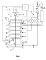
- Fig.1 represents a diagram of an example of a vacuum pump 1.
- the vacuum pump 1 may be a primary pump such as a dry pump configured to have its output 1b evacuating at an atmospheric pressure as represented in Fig.1 .
- the invention may be applied on a turbomolecular pump configured to be coupled with a primary pump or any other types of vacuum pumps known by the man skilled in the art.
- the vacuum pump 1 comprises an input 1a configured to be coupled to a vacuum chamber where the vacuum needs to be set.
- the vacuum pump 1 comprises a stator 3 inside which two rotors 5 (in Fig.1 , the second rotor is hidden by the first rotor) rotating around two parallel axis X and defining a plurality of pumping stages, five in the present case, noted T1, T2, T3, T4 and T5.
- the rotors 5 are configured for drawing in the gas noted F1 at the input 1a, compress the said gas F1 and expel it toward an output 1b of the vacuum pump 1.
- the vacuum pump 1 also comprises an electric motor 7 configured for rotating the rotors 5.
- the pumping stages T1...T5 are coupled in series so that the gas F1 is transmitted through the different stages T1...T5.
- the vacuum pump 1 also comprises an injection purge gas device 9 comprising at least one duct configured to be coupled to a purge gas supply.
- the purge gas is noted F2.
- the injection purge gas device 9 comprises several ducts coupled to the different stages T1...T5 of the vacuum pump 1.
- One of the duct is also coupled to a bearing 11.
- the injection of purge gas F2 enables protecting the different parts of the vacuum pump 1 in contact with the pumped gas F1 which may be aggressive and may damage the vacuum pump 1.
- the vacuum pump 1 may also comprise a hydraulic circuit (not represented) configured for circulating a cooling fluid in the stator 3, for example next to the rotors 5, or next to the bearings 11.
- the vacuum pump 1 also comprises a plurality of sensors configured for measuring parameters associated with a state of the vacuum pump 1, these parameters may have cross-correlation.
- the sensors may be sensors from the following list:
- the vacuum pump 1 also comprises a control unit 21 configured for retrieving measurements from the plurality of sensors mentioned previously.
- the control unit 21 is also configured for determining an operating point of the vacuum pump 1 based on one side on the retrieved measurements and on the other side on an operating mode of the vacuum pump 1 selected by a user.
- a plurality of operating modes may be predefined during manufacturing of the vacuum pump 1. One of the predefined modes is selected by the user according to its application. The different operating modes refer for example to one of the following operating modes:
- the control unit 21 is also configured for applying the determined operating point, for example by controlling the rotational speed of the rotors 5 via the electric motor 7, by setting the different valves or by controlling the purge gas flow rate or the cooling fluid flow rate.
- Such determination and application of the operating point are achieved recursively over time, for example with a given frequency.
- the frequency may be chosen according to the capacity of the different components and may be a few Hz.
- Such recursive determination over time enable an adaptation of the operating point according to the evolution of the different measured parameters and therefore an optimization of the control of the vacuum pump 1.
- the control unit 21 is configured to apply fuzzy logic commands to determine the operating point.
- the fuzzy logic commands refer to the application of predefined rules that depend on the values of the measured parameters with respect to predetermined thresholds associated with different states of the vacuum pump 1.
- the different thresholds may refer to ranges of values that can overlap with each other so that the transition between two states of the vacuum pump 1 may be progressive.
- Fig.2 represents an example of fuzzy logic rules associated with a rotor temperature.
- the abscissa refers to a rotor 5 temperature and the ordinate refers to the memberships to set, that is to say the qualifiers or variables associated to different ranges of temperature.
- five qualifiers are used to cover the whole range of temperature of the rotor 5 but any numbers of qualifiers may be used depending on the required accuracy.
- the different qualifiers refer respectively to a cold state below 30°C, a cool state around 45°C, a moderate state around 60°C, a warm state around 75°C and a hot state above 90°C. As can be seen in Fig.2 , a given state overlaps with the adjacent states.
- the different parameters determining the state of the vacuum pump 1 may be mapped with qualifiers.
- the number of qualifiers may be different for the different parameters.
- different rulesets may be defined for the different operating modes and the rulesets associated with the chosen mode may be applied to control the vacuum pump 1.
- a vacuum pump 1 with parameters associated with the rotor 5 speed, the rotor 5 temperature and the pressure in the vacuum chamber connected upstream of the vacuum pump 1.
- the values of these parameters are given by respective sensors and are mapped with low, nominal and high variables.
- This example has a limited number of parameters and a limited number of qualifiers for each parameter to remain simple but in practice, other parameters of the vacuum pump 1 may also be taken into account as indicated by the list of sensors described above.
- a primary goal of a ruleset may be to meet the desired temperature or to fall below it.
- a secondary goal may be to save energy and reduce wear by lowering the rotor speed if possible.
- a boost mode can be used to improve the performance and reduce the time required until the vacuum chamber is sufficiently evacuated.
- a first possible ruleset associated with a normal mode may be as follow:
- a second possible ruleset associated with a performance mode may be as follow:
- the operating point is determined by the control unit 21 based on the sensors measurements and the ruleset of the selected operating mode.
- the control unit 21 is then configured to apply the determined operating point.
- the application of the determined operating point refers for example to the control of a supply current controlling the rotational speed of the rotor 5. Such application may also refer to the control of a flow rate of a cooling fluid or to the control of any other controlling parameters of the vacuum pump 1.
- the application of a fuzzy logic enables controlling efficiently the vacuum pump to reach an optimal operating point without requiring important processing means to take into account the cross-correlation between the different parameters.
- control unit 21 comprises a neural network configured for determining the operating point of the vacuum pump 1 based on the retrieved measurements.
- the neural network is configured to analyse the evolution of the state of the vacuum pump 1 and the evolution of the measured parameters over time in order to determine the influence of the different controlling parameters.
- a learning phase comprising sequential steps of activation of the different features of the pump may be required to set up the neural network.
- the permanent analysis achieved by the neural network enables determining the optimal operating point according to the searched goal and the different constraints.
- these constraints refer to a preferred operating mode which is selected by the user in order to set different thresholds associated with different parameters for example the temperature threshold for an operating mode maximizing the lifetime will be lower than the temperature threshold associated with an operating mode maximizing the performance (minimal time to reach the desired pressure).
- the control unit 21 may thus be configured to take into account current and past retrieved measurements for determining the operating point of the vacuum pump 1. Furthermore, each new measurement may be used to update a threshold value or to update the influence of a parameter on the state of the vacuum pump 1.
- the neural network may also be able to determine a configuration or a function of different components of the vacuum pump 1 with respect to each other.
- control unit 21 comprises a combination of fuzzy logic defining rulesets and neural network configured to adapt the values associated to the qualifiers defined in the rulesets.
- the operating point is then defined based on current and previous measurements and the values associated with the qualifiers may be adapted over time.
- control unit 21 may automatically adapt the determination of the operating point to the replacement of a component of the vacuum pump 1, even if the new components has different features than the replaced component.
- the control unit 21 may be provided through the use of a dedicated hardware as well as hardware capable of executing software.
- the control unit 21 may be provided by a single dedicated processor, by a single shared processor, or by a plurality of individual processors, some of which may be shared.
- explicit use of the term "processor” should not be construed to refer exclusively to hardware capable of executing software, and may implicitly include, without limitation, microcontroller, digital signal processor (DSP) hardware, network processor, application specific integrated circuit (ASIC), field programmable gate array (FPGA), read-only memory (ROM) for storing software, random access memory (RAM), and non-volatile storage.
- DSP digital signal processor
- ASIC application specific integrated circuit
- FPGA field programmable gate array
- ROM read-only memory
- RAM random access memory
- non-volatile storage Other hardware, conventional and/or custom, may also be included.
- the vacuum pump 1 comprises communication means which may be wireless communications means to enables communications between different components of the vacuum pump 1 notably between the control unit 21 and the different sensors as well as between the control unit 21 and the controlling means enabling the application of an operating point to the vacuum pump 1 (control of the rotational speed of the rotors 5).
- communication means may be wireless communications means to enables communications between different components of the vacuum pump 1 notably between the control unit 21 and the different sensors as well as between the control unit 21 and the controlling means enabling the application of an operating point to the vacuum pump 1 (control of the rotational speed of the rotors 5).
- the present invention may also be applied on a vacuum system comprising one or several vacuum pumps and possibly additional components such as valves.
- the different features described for the vacuum pump 1 may be applied to the vacuum system 1.
- Figure 3 represents an example of a vacuum system 100 comprising a roughing pump 101, a first turbomolecular pump 103 coupled to the roughing pump 101 via a first electronic valve 105, a second turbomolecular pump 107 coupled to the first turbomolecular pump 103 via a second electronic valve 109 and a vacuum chamber 115 coupled to the second turbomolecular pump 107, the three pumps 101, 103 and 107 are therefore connected in series.
- the vacuum system 100 also comprises a first pressure gauge 111 arranged between the roughing pump 101 and the first turbomolecular pump 103 and a second pressure gauge 113 arranged between the first turbomolecular pump 103 and the second turbomolecular pump 107.
- the vacuum system 100 presented in fig.3 remains simple for sake of clarity but in practice, such vacuum system 100 would comprise many other sensors such as temperature sensors arranged within the different vacuum pumps 101, 103, 107, flow rate sensors associated with the purge gas supplying device or the cooling fluid circuit of the different vacuum pumps 101, 103, 107 and possibly other types of sensors as disclosed previously.
- the vacuum system 100 also comprises a control unit 21 capable of applying fuzzy logic and/ or neural network as disclosed previously in the case of a vacuum pump 1 and is configured to recursively determine an operating point of the vacuum system (activation and control of the different pumps as well as control of the different valves) based on the different measurements retrieved from the different sensors of the vacuum system and according to an operating mode selected by the user.
- a control unit 21 capable of applying fuzzy logic and/ or neural network as disclosed previously in the case of a vacuum pump 1 and is configured to recursively determine an operating point of the vacuum system (activation and control of the different pumps as well as control of the different valves) based on the different measurements retrieved from the different sensors of the vacuum system and according to an operating mode selected by the user.
- control unit 21 comprises a neural network.
- the roughing pump 101 When starting the evacuation of the vacuum chamber 115, the roughing pump 101 will be turned on which will cause a pressure drop in both first and second pressure gauges 111 and 113.
- the first turbomolecular pump 103 will be turned on which causes a pressure drop in the second pressure gauge 113 but not in the first pressure gauge 111.
- the neural network of the control unit 21 may determine that the first pressure gauge 111 is located between the roughing pump 101 and the first turbomolecular pump 103.
- the second turbomolecular pump 107 is turned on which does not cause any pressure drop in the first pressure gauge 111 and in the second pressure gauge 113.
- the neural network may then determine that the second pressure gauge 113 is located between the first turbomolecular pump 103 and the second turbomolecular pumps 107.
- a neural network of a control unit 21 associated with the vacuum system 100 may establish some rules to control the vacuum system 100.
- the control unit 21 may decide to set the first turbomolecular pump 103 in a stand-by mode as long as the pressure in the second pressure gauge 113 or the drive power of the second turbomolecular pump 107 does not significantly increase in order to decrease the wear and power consumption associated with the first turbomolecular pump 103.
- the second turbomolecular pump 107 could not be switched to a stand-by mode as there is no pressure gauge to monitor the impact of such adaptation in a stand-by mode.
- Such monitoring of the behaviour of the vacuum system 100 may be achieved constantly over time so that the control unit 21 may adapt to a change during the process. For example, if an increase of the gas load to be evacuated from the vacuum chamber 115 occurs, the stand-by mode of first turbomolecular pump 103 may be disabled to ensure the safety of the vacuum system 100.
- control unit 21 is capable of detecting such replacement and to adapt the rules and the determination of the operating point to take into account the features of the new element.
- the vacuum system 100 is then constantly adapting to any changes that can occur during the lifetime of the vacuum system 100.
- control unit 21 may be configured for assessing a remaining useful lifetime of a vacuum pump 1 or parts of the vacuum pump 1 based on the operating points applied over time and/or from the measurements achieved over time and for emitting a warning signal when the determined remaining useful lifetime is below a predetermined threshold.
- estimation of the remaining useful lifetime takes into account the different states of the vacuum pump 1 over time, such estimation may be very accurate so that the lifetime of the parts is optimized while limiting the risk of a failure.
- control unit 21 may also apply in the case of a vacuum system 100 for assessing a remaining useful lifetime of the elements of the vacuum system 100 such as the vacuum pumps 101, 103, 107 or the valves 105, 109 or any other elements of the vacuum system 100.
- the present invention enables optimizing the functioning of the vacuum pump of the vacuum system according to the application and the requirements of the user. Moreover, such adaptation of the vacuum equipment to the users requirements are achieved automatically by the vacuum equipment and does not require a taylor-made configuration of the vacuum equipment during manufacturing to adapt the configuration of the said equipment to the application and the requirements of the user.
- neural network processing means enable adapting the control of the vacuum equipment to any changes in the configuration of the vacuum equipment.
- the present invention also provides an accurate estimation of the remaining useful lifetime to warn the user when an element requires maintenance or replacement before a breakdown occurs.
Landscapes
- Engineering & Computer Science (AREA)
- Mechanical Engineering (AREA)
- General Engineering & Computer Science (AREA)
- Computer Hardware Design (AREA)
- Compressors, Vaccum Pumps And Other Relevant Systems (AREA)
- Non-Positive Displacement Air Blowers (AREA)
- Control Of Positive-Displacement Pumps (AREA)
- Applications Or Details Of Rotary Compressors (AREA)
Priority Applications (4)
| Application Number | Priority Date | Filing Date | Title |
|---|---|---|---|
| EP22315002.0A EP4206468A1 (de) | 2022-01-04 | 2022-01-04 | Vakuumpumpe und vakuumsystem |
| PCT/EP2023/050036 WO2023131592A1 (en) | 2022-01-04 | 2023-01-03 | Vacuum pump and vacuum system |
| JP2024540558A JP7821295B2 (ja) | 2022-01-04 | 2023-01-03 | 真空ポンプおよび真空システム |
| EP23700390.0A EP4460633A1 (de) | 2022-01-04 | 2023-01-03 | Vakuumpumpe und vakuumsystem |
Applications Claiming Priority (1)
| Application Number | Priority Date | Filing Date | Title |
|---|---|---|---|
| EP22315002.0A EP4206468A1 (de) | 2022-01-04 | 2022-01-04 | Vakuumpumpe und vakuumsystem |
Publications (1)
| Publication Number | Publication Date |
|---|---|
| EP4206468A1 true EP4206468A1 (de) | 2023-07-05 |
Family
ID=80775296
Family Applications (2)
| Application Number | Title | Priority Date | Filing Date |
|---|---|---|---|
| EP22315002.0A Withdrawn EP4206468A1 (de) | 2022-01-04 | 2022-01-04 | Vakuumpumpe und vakuumsystem |
| EP23700390.0A Pending EP4460633A1 (de) | 2022-01-04 | 2023-01-03 | Vakuumpumpe und vakuumsystem |
Family Applications After (1)
| Application Number | Title | Priority Date | Filing Date |
|---|---|---|---|
| EP23700390.0A Pending EP4460633A1 (de) | 2022-01-04 | 2023-01-03 | Vakuumpumpe und vakuumsystem |
Country Status (3)
| Country | Link |
|---|---|
| EP (2) | EP4206468A1 (de) |
| JP (1) | JP7821295B2 (de) |
| WO (1) | WO2023131592A1 (de) |
Citations (3)
| Publication number | Priority date | Publication date | Assignee | Title |
|---|---|---|---|---|
| US5443368A (en) * | 1993-07-16 | 1995-08-22 | Helix Technology Corporation | Turbomolecular pump with valves and integrated electronic controls |
| US6022195A (en) * | 1988-09-13 | 2000-02-08 | Helix Technology Corporation | Electronically controlled vacuum pump with control module |
| WO2003100259A1 (en) * | 2002-05-22 | 2003-12-04 | Applied Materials, Inc. | Variable speed vacuum pump control method and apparatus |
Family Cites Families (8)
| Publication number | Priority date | Publication date | Assignee | Title |
|---|---|---|---|---|
| US4918930A (en) * | 1988-09-13 | 1990-04-24 | Helix Technology Corporation | Electronically controlled cryopump |
| JP2002541541A (ja) | 1999-04-07 | 2002-12-03 | アルカテル | 真空チャンバ内の圧力を調整するためのシステム、このシステムを装備した真空ポンピングユニット |
| US6739840B2 (en) | 2002-05-22 | 2004-05-25 | Applied Materials Inc | Speed control of variable speed pump |
| JP6115937B2 (ja) | 2013-02-05 | 2017-04-19 | 株式会社甲府明電舎 | 圧縮機用のモータとその制御方法 |
| US20170218790A1 (en) | 2016-02-01 | 2017-08-03 | General Electric Company | Systems and Methods of Predicting Physical Parameters for a Combustion Fuel System |
| JP6534358B2 (ja) | 2016-03-22 | 2019-06-26 | 住友重機械工業株式会社 | クライオポンプ、クライオポンプ制御装置及びクライオポンプ制御方法 |
| EP3473858B1 (de) * | 2017-10-17 | 2020-07-01 | Pfeiffer Vacuum Gmbh | Verfahren zur lebensdaueroptimierung von wälzlagern einer vakuumpumpe |
| JP7019513B2 (ja) | 2018-06-05 | 2022-02-15 | 株式会社荏原製作所 | 制御装置、制御システム、制御方法、プログラム及び機械学習装置 |
-
2022
- 2022-01-04 EP EP22315002.0A patent/EP4206468A1/de not_active Withdrawn
-
2023
- 2023-01-03 WO PCT/EP2023/050036 patent/WO2023131592A1/en not_active Ceased
- 2023-01-03 JP JP2024540558A patent/JP7821295B2/ja active Active
- 2023-01-03 EP EP23700390.0A patent/EP4460633A1/de active Pending
Patent Citations (3)
| Publication number | Priority date | Publication date | Assignee | Title |
|---|---|---|---|---|
| US6022195A (en) * | 1988-09-13 | 2000-02-08 | Helix Technology Corporation | Electronically controlled vacuum pump with control module |
| US5443368A (en) * | 1993-07-16 | 1995-08-22 | Helix Technology Corporation | Turbomolecular pump with valves and integrated electronic controls |
| WO2003100259A1 (en) * | 2002-05-22 | 2003-12-04 | Applied Materials, Inc. | Variable speed vacuum pump control method and apparatus |
Also Published As
| Publication number | Publication date |
|---|---|
| EP4460633A1 (de) | 2024-11-13 |
| JP2025502855A (ja) | 2025-01-28 |
| WO2023131592A1 (en) | 2023-07-13 |
| JP7821295B2 (ja) | 2026-02-26 |
Similar Documents
| Publication | Publication Date | Title |
|---|---|---|
| EP3514389B1 (de) | Pumpvorrichtung, testbetriebsverfahren der pumpvorrichtung, motoranordnung und verfahren zur identifizierung einer anormalen vibration einer motoranordnung | |
| US10386869B2 (en) | Automated system to determine variable frequency drive skip frequency bands for vibration control | |
| US20160265520A1 (en) | Electronic control for a rotary fluid device | |
| CN107559200B (zh) | 平衡型罗茨真空泵系统及其控制方法 | |
| CN102753827A (zh) | 调整泵的速度的装置和方法 | |
| CN113465113B (zh) | 空调低温制冷的控制方法、装置及空调器 | |
| US11761443B2 (en) | Compressor and monitoring system | |
| WO2020028255A1 (en) | Active bearing temperature control | |
| JP2020508413A (ja) | 制御装置を備えたポンプシステム | |
| JP2019120146A (ja) | 電動機組立体、ポンプ装置、および、電動機組立体の異常振動を特定する方法 | |
| US10900489B2 (en) | Automatic pumping system commissioning | |
| US8893980B2 (en) | Delayed execution and automated model detection for air moving devices | |
| CN117222816A (zh) | 用于动力式压缩机的质量流量内插系统及方法 | |
| US6671459B1 (en) | DC motor control method and apparatus | |
| WO2023131592A1 (en) | Vacuum pump and vacuum system | |
| CN112177910A (zh) | 一种移动冰箱的压缩机转速控制方法和移动冰箱 | |
| US12085085B2 (en) | Vacuum pump system and control method | |
| CN112513469A (zh) | 真空泵 | |
| RU2766499C2 (ru) | Способ эксплуатации циркуляционного насоса, а также циркуляционный насос для осуществления этого способа | |
| JP5985182B2 (ja) | 真空ポンプの通気方法および真空ポンプを備えた装置 | |
| EP4039978A1 (de) | Fluidmaschinenvorrichtung | |
| CN211508952U (zh) | 感应电机 | |
| US11487262B2 (en) | Method and apparatus for protecting pump units from cyber attacks | |
| CN118442296A (zh) | 抽真空系统的控制方法、装置、电子设备及存储介质 | |
| KR102537407B1 (ko) | 진공펌프용 스마트 인공지능 모듈 |
Legal Events
| Date | Code | Title | Description |
|---|---|---|---|
| PUAI | Public reference made under article 153(3) epc to a published international application that has entered the european phase |
Free format text: ORIGINAL CODE: 0009012 |
|
| STAA | Information on the status of an ep patent application or granted ep patent |
Free format text: STATUS: THE APPLICATION HAS BEEN PUBLISHED |
|
| AK | Designated contracting states |
Kind code of ref document: A1 Designated state(s): AL AT BE BG CH CY CZ DE DK EE ES FI FR GB GR HR HU IE IS IT LI LT LU LV MC MK MT NL NO PL PT RO RS SE SI SK SM TR |
|
| STAA | Information on the status of an ep patent application or granted ep patent |
Free format text: STATUS: REQUEST FOR EXAMINATION WAS MADE |
|
| 17P | Request for examination filed |
Effective date: 20230915 |
|
| RBV | Designated contracting states (corrected) |
Designated state(s): AL AT BE BG CH CY CZ DE DK EE ES FI FR GB GR HR HU IE IS IT LI LT LU LV MC MK MT NL NO PL PT RO RS SE SI SK SM TR |
|
| STAA | Information on the status of an ep patent application or granted ep patent |
Free format text: STATUS: EXAMINATION IS IN PROGRESS |
|
| 17Q | First examination report despatched |
Effective date: 20241126 |
|
| STAA | Information on the status of an ep patent application or granted ep patent |
Free format text: STATUS: THE APPLICATION IS DEEMED TO BE WITHDRAWN |
|
| 18D | Application deemed to be withdrawn |
Effective date: 20250327 |