EP4206573A1 - Réfrigérateur et son procédé de commande - Google Patents
Réfrigérateur et son procédé de commande Download PDFInfo
- Publication number
- EP4206573A1 EP4206573A1 EP21868441.3A EP21868441A EP4206573A1 EP 4206573 A1 EP4206573 A1 EP 4206573A1 EP 21868441 A EP21868441 A EP 21868441A EP 4206573 A1 EP4206573 A1 EP 4206573A1
- Authority
- EP
- European Patent Office
- Prior art keywords
- chamber
- air
- temperature
- supply port
- humidity
- Prior art date
- Legal status (The legal status is an assumption and is not a legal conclusion. Google has not performed a legal analysis and makes no representation as to the accuracy of the status listed.)
- Granted
Links
Images

Classifications
-
- F—MECHANICAL ENGINEERING; LIGHTING; HEATING; WEAPONS; BLASTING
- F25—REFRIGERATION OR COOLING; COMBINED HEATING AND REFRIGERATION SYSTEMS; HEAT PUMP SYSTEMS; MANUFACTURE OR STORAGE OF ICE; LIQUEFACTION SOLIDIFICATION OF GASES
- F25D—REFRIGERATORS; COLD ROOMS; ICE-BOXES; COOLING OR FREEZING APPARATUS NOT OTHERWISE PROVIDED FOR
- F25D11/00—Self-contained movable devices, e.g. domestic refrigerators
-
- F—MECHANICAL ENGINEERING; LIGHTING; HEATING; WEAPONS; BLASTING
- F25—REFRIGERATION OR COOLING; COMBINED HEATING AND REFRIGERATION SYSTEMS; HEAT PUMP SYSTEMS; MANUFACTURE OR STORAGE OF ICE; LIQUEFACTION SOLIDIFICATION OF GASES
- F25D—REFRIGERATORS; COLD ROOMS; ICE-BOXES; COOLING OR FREEZING APPARATUS NOT OTHERWISE PROVIDED FOR
- F25D17/00—Arrangements for circulating cooling fluids; Arrangements for circulating gas, e.g. air, within refrigerated spaces
- F25D17/04—Arrangements for circulating cooling fluids; Arrangements for circulating gas, e.g. air, within refrigerated spaces for circulating air, e.g. by convection
- F25D17/06—Arrangements for circulating cooling fluids; Arrangements for circulating gas, e.g. air, within refrigerated spaces for circulating air, e.g. by convection by forced circulation
- F25D17/062—Arrangements for circulating cooling fluids; Arrangements for circulating gas, e.g. air, within refrigerated spaces for circulating air, e.g. by convection by forced circulation in household refrigerators
-
- F—MECHANICAL ENGINEERING; LIGHTING; HEATING; WEAPONS; BLASTING
- F25—REFRIGERATION OR COOLING; COMBINED HEATING AND REFRIGERATION SYSTEMS; HEAT PUMP SYSTEMS; MANUFACTURE OR STORAGE OF ICE; LIQUEFACTION SOLIDIFICATION OF GASES
- F25D—REFRIGERATORS; COLD ROOMS; ICE-BOXES; COOLING OR FREEZING APPARATUS NOT OTHERWISE PROVIDED FOR
- F25D21/00—Defrosting; Preventing frosting; Removing condensed or defrost water
- F25D21/04—Preventing the formation of frost or condensate
-
- F—MECHANICAL ENGINEERING; LIGHTING; HEATING; WEAPONS; BLASTING
- F25—REFRIGERATION OR COOLING; COMBINED HEATING AND REFRIGERATION SYSTEMS; HEAT PUMP SYSTEMS; MANUFACTURE OR STORAGE OF ICE; LIQUEFACTION SOLIDIFICATION OF GASES
- F25D—REFRIGERATORS; COLD ROOMS; ICE-BOXES; COOLING OR FREEZING APPARATUS NOT OTHERWISE PROVIDED FOR
- F25D23/00—General constructional features
- F25D23/02—Doors; Covers
-
- F—MECHANICAL ENGINEERING; LIGHTING; HEATING; WEAPONS; BLASTING
- F25—REFRIGERATION OR COOLING; COMBINED HEATING AND REFRIGERATION SYSTEMS; HEAT PUMP SYSTEMS; MANUFACTURE OR STORAGE OF ICE; LIQUEFACTION SOLIDIFICATION OF GASES
- F25D—REFRIGERATORS; COLD ROOMS; ICE-BOXES; COOLING OR FREEZING APPARATUS NOT OTHERWISE PROVIDED FOR
- F25D29/00—Arrangement or mounting of control or safety devices
-
- F—MECHANICAL ENGINEERING; LIGHTING; HEATING; WEAPONS; BLASTING
- F25—REFRIGERATION OR COOLING; COMBINED HEATING AND REFRIGERATION SYSTEMS; HEAT PUMP SYSTEMS; MANUFACTURE OR STORAGE OF ICE; LIQUEFACTION SOLIDIFICATION OF GASES
- F25D—REFRIGERATORS; COLD ROOMS; ICE-BOXES; COOLING OR FREEZING APPARATUS NOT OTHERWISE PROVIDED FOR
- F25D2317/00—Details or arrangements for circulating cooling fluids; Details or arrangements for circulating gas, e.g. air, within refrigerated spaces, not provided for in other groups of this subclass
- F25D2317/06—Details or arrangements for circulating cooling fluids; Details or arrangements for circulating gas, e.g. air, within refrigerated spaces, not provided for in other groups of this subclass with forced air circulation
- F25D2317/062—Details or arrangements for circulating cooling fluids; Details or arrangements for circulating gas, e.g. air, within refrigerated spaces, not provided for in other groups of this subclass with forced air circulation along the inside of doors
-
- F—MECHANICAL ENGINEERING; LIGHTING; HEATING; WEAPONS; BLASTING
- F25—REFRIGERATION OR COOLING; COMBINED HEATING AND REFRIGERATION SYSTEMS; HEAT PUMP SYSTEMS; MANUFACTURE OR STORAGE OF ICE; LIQUEFACTION SOLIDIFICATION OF GASES
- F25D—REFRIGERATORS; COLD ROOMS; ICE-BOXES; COOLING OR FREEZING APPARATUS NOT OTHERWISE PROVIDED FOR
- F25D2323/00—General constructional features not provided for in other groups of this subclass
- F25D2323/02—Details of doors or covers not otherwise covered
- F25D2323/023—Door in door constructions
-
- F—MECHANICAL ENGINEERING; LIGHTING; HEATING; WEAPONS; BLASTING
- F25—REFRIGERATION OR COOLING; COMBINED HEATING AND REFRIGERATION SYSTEMS; HEAT PUMP SYSTEMS; MANUFACTURE OR STORAGE OF ICE; LIQUEFACTION SOLIDIFICATION OF GASES
- F25D—REFRIGERATORS; COLD ROOMS; ICE-BOXES; COOLING OR FREEZING APPARATUS NOT OTHERWISE PROVIDED FOR
- F25D2700/00—Means for sensing or measuring; Sensors therefor
- F25D2700/12—Sensors measuring the inside temperature
-
- F—MECHANICAL ENGINEERING; LIGHTING; HEATING; WEAPONS; BLASTING
- F25—REFRIGERATION OR COOLING; COMBINED HEATING AND REFRIGERATION SYSTEMS; HEAT PUMP SYSTEMS; MANUFACTURE OR STORAGE OF ICE; LIQUEFACTION SOLIDIFICATION OF GASES
- F25D—REFRIGERATORS; COLD ROOMS; ICE-BOXES; COOLING OR FREEZING APPARATUS NOT OTHERWISE PROVIDED FOR
- F25D2700/00—Means for sensing or measuring; Sensors therefor
- F25D2700/12—Sensors measuring the inside temperature
- F25D2700/121—Sensors measuring the inside temperature of particular compartments
-
- F—MECHANICAL ENGINEERING; LIGHTING; HEATING; WEAPONS; BLASTING
- F25—REFRIGERATION OR COOLING; COMBINED HEATING AND REFRIGERATION SYSTEMS; HEAT PUMP SYSTEMS; MANUFACTURE OR STORAGE OF ICE; LIQUEFACTION SOLIDIFICATION OF GASES
- F25D—REFRIGERATORS; COLD ROOMS; ICE-BOXES; COOLING OR FREEZING APPARATUS NOT OTHERWISE PROVIDED FOR
- F25D29/00—Arrangement or mounting of control or safety devices
- F25D29/005—Mounting of control devices
Definitions
- the present invention relates to the technical field of refrigeration and freezing, and in particular to a refrigerator and a control method therefor.
- a conventional refrigerator provided with only a refrigeration chamber, a freezing chamber and a variable-temperature chamber can no longer meet the diversified needs of users on storage spaces.
- a composite door technology has emerged in the field of refrigerators. It is known to all that a conventional refrigerator door body is used to open or close a refrigerating chamber of a refrigerator body, and at most a bottle holder for placing bottled products is disposed at a lining of a refrigeration door body.
- a refrigerator with a composite door body is improved in structure and function of the door body, where the door body includes a main door and a secondary door, and the main door is used to open or close the refrigerating chamber.
- the main door defines a door chamber with an open front side, and the secondary door is used to open or close the door chamber. During rotation of the main door, the secondary door is kept closed.
- the door chamber may be used to place to-be-stored objects, and a user just needs to open the secondary door to take or put objects without opening the main door. This achieves more convenient and more efficient operation, and also avoids excessive loss of cold energy caused by frequent opening of the main door.
- the present invention aims to provide a refrigerator and a control method for the refrigerator to at least overcome one of the above shortcomings existing in the prior art.
- the present invention aims to reduce or avoid condensation on an inner wall of a door chamber.
- the present invention further aims to avoid adverse effects of temperature and humidity fluctuation in a refrigerator body chamber on a temperature and a humidity in the door chamber.
- the present invention provides a control method for a refrigerator.
- the refrigerator includes a refrigerator body having a front side opened to define a first chamber, and a door body configured to open or close the first chamber;
- the door body includes a main door and a secondary door, where the main door is configured to open or close the first chamber and defines a second chamber, the secondary door is configured to open or close the second chamber, and a rear side of the main door is provided with an air supply port configured to introduce cold air in the first chamber into the second chamber; and the control method includes:
- control method further includes:
- the step of acquiring a temperature T 3 of the inner wall of the second chamber includes: detecting a temperature of a rear wall of the second chamber, and taking the temperature as the temperature T 3 of the inner wall.
- a distance from a temperature detection point on the rear wall of the second chamber to the air supply port is shorter than or equal to a first preset distance.
- a distance from a detection point of the air temperature T 2 to the air supply port is shorter than or equal to a second preset distance.
- control method further includes:
- distances from a detection point of the air temperature T 1 and a detection point of the relative air humidity ⁇ 1 to the air supply port are shorter than or equal to a third preset distance.
- a fan is mounted at the air supply port; and in the control method, the step of if ⁇ 3 ⁇ 0 , enabling the air supply port to supply air to the second chamber, otherwise enabling the air supply port to stop supplying air to the second chamber includes: if ⁇ 3 ⁇ 0 , turning on the fan to enable the air supply port to supply air to the second chamber, otherwise turning off the fan to enable the air supply port to stop supplying air to the second chamber.
- the present invention further provides a refrigerator, including:
- the first chamber is a refrigeration chamber; the air supply port is disposed at the top of a rear side of the main door; and the bottom of the rear side of the main door is further provided with an air return port for enabling air in the second chamber to flow to the first chamber.
- the refrigerator and the control method therefor provided by the present invention solve the problem that condensation easily occurs on the inner wall of the second chamber defined by the door body in a composite door type refrigerator.
- the inventors have realized that one significant reason for probable occurrence of condensation on the inner wall of the second chamber is that high-humidity air is introduced from the first chamber of the refrigerator body. Especially when the first chamber is just opened or closed, external air with relatively high humidity and temperature enters the first chamber, and if the air subsequently enters the second chamber, it is easy to produce condensation on the inner wall of the second chamber.
- the expected relative humidity ⁇ 3 of the air in the first chamber when the temperature changes to the air temperature T 2 in the second chamber, and the relative air humidity threshold ⁇ 0 at which the air begins to condense on the inner wall of the second chamber are calculated first and are compared; only when ⁇ 3 ⁇ 0 , the air supply port is enabled to supply air to the second chamber; otherwise, the air support port is enabled to stop supplying air to the second chamber, thereby avoiding the problem about production of condensation on the inner wall of the second chamber caused by introduction of the cold air from the first chamber to the second chamber immediately after the first chamber is just opened or closed or after other operations that cause increase of the air humidity in the first chamber.
- the external high-humidity and high-temperature air can be prevented from entering the second chamber after the first chamber is opened or closed, so that adverse effects of temperature fluctuation in the first chamber on a temperature and a humidity in the second chamber are prevented as well. In this way, the temperature and humidity of the air in the second chamber are kept at a reasonable level.
- the expected relative humidity ⁇ 3 of the air in the first chamber when the temperature changes to T 2 after the air enters the second chamber is predicted based on the absolute air humidity ⁇ 1 in the first chamber and the air temperature T 2 , so as to determine whether condensation will be produced on the inner wall of the second chamber after the air enters the first chamber.
- Such calculation manner ingeniously realizes prediction on a condensation condition and avoids production of condensation.
- the distances from the detection point of the air temperature T 1 in the first chamber, the detection point of the relative air humidity ⁇ 1 in the first chamber, the temperature detection point on the rear wall of the second chamber, and the detection point of the air temperature T 2 of the second chamber to the air supply port are limited to make sure that the above detection points are closer to the air supply port, so that temperature and humidity detection is specially performed on an air flow that first enters the air supply port in a later period, thereby achieving more accurate prediction on whether condensation will be produced after the air flow in the first chamber flows into the second chamber.
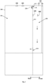
- FIG. 1 is a schematic structural diagram of a refrigerator according to an embodiment of the present invention.
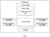
- FIG. 2 is a schematic block diagram of a refrigerator according to an embodiment of the present invention.
- An embodiment of the present invention provides a control method for a refrigerator.
- the refrigerator includes a refrigerator body 100, a door body 200 and a controller 700.
- the door body 200 includes a main door 210 and a secondary door 220, where the main door 210 is configured to open or close the first chamber 101 and defines a second chamber 201, the secondary door 220 is configured to open or close the second chamber 201, and a rear side of the main door 210 is provided with an air supply port 212 configured to introduce cold air in the first chamber 101 into the second chamber 201. After cold air enters the second chamber 201, the second chamber 201 is refrigerated.
- the main door 210 may be rotatably mounted on the refrigerator body 100 at the front side of the refrigerator body 100; and a front side of the main door 210 is opened to define the second chamber 201, and the secondary door 220 is rotatably mounted on the main door 210 at the front side of the main door 210.
- the controller 700 includes a processor 720 and a memory 710, where the memory 710 stores a computer program 711, and when the computer program 711 is executed by the processor 720, the control method for a refrigerator according to this embodiment is implemented.
- the refrigerator can perform refrigeration through a vapor compression refrigeration circulation system, a semiconductor refrigeration system, or other ways.
- the chambers inside the refrigerator may be classified into a refrigeration chamber, a freezing chamber and a variable-temperature chamber.
- a temperature in the refrigeration chamber is generally controlled between 2°C and 10°C, preferably between 4°C and 7°C.
- a temperature in the freezing chamber is generally controlled between -22°C and -14°C.
- a temperature in the variable-temperature chamber may be adjusted between -18°C and 8°C so as to realize a temperature variation effect.
- Different types of objects should be stored at different optimal storage temperatures, and also should be stored in different storage chambers. For example, fruit and vegetable foods are suitable for being stored in a refrigeration chamber, while meat foods are suitable for being stored in a freezing chamber.
- the first chamber 101 is a refrigeration chamber.
- the air supply port 212 may be disposed at the top of the rear side of the main door 210, and the bottom of the rear side of the main door 210 is further provided with an air return port 214 for enabling air in the second chamber 201 to flow to the first chamber 101.
- cold air due to its relatively large density, sinks and flows down to sequentially refrigerate regions at all heights of the second chamber 201, and the air flows back to the first chamber 101 via the air return port 214 at the bottom of the second chamber 201 after the temperature of the air rises gradually.
- smoother air path circulation is formed, which improves a refrigeration effect of the second chamber 201. It can be understood that air returning can be implemented by the air supply port 212 if no air return port 214 is provided.
- FIG. 3 is a schematic diagram of a control method for a refrigerator according to an embodiment of the present invention.
- the control method for a refrigerator according to this embodiment of the present invention is applicable to the refrigerators according to all the foregoing embodiments of the present invention.
- the control method for a refrigerator includes: Step S302: acquiring an absolute air humidity ⁇ 1 of the first chamber 101 and an air temperature T 2 of the second chamber 201.
- the absolute air humidity ⁇ 1 of the first chamber 101 may be directly measured.
- the absolute air humidity ⁇ 1 is preferably indirectly obtained through calculation, so that a more accurate result can be obtained. Specifically, an air temperature T 1 in the first chamber 101 and a relative air humidity ⁇ 1 in the first chamber 101 are detected first, and the absolute air humidity ⁇ 1 is calculated based on the air temperature T 1 and the relative air humidity ⁇ 1 .
- Step S304 calculating an expected relative humidity ⁇ 3 of air in the first chamber 101 when the temperature changes to T 2 based on the absolute air humidity ⁇ 1 and the air temperature T 2 .
- a relative air humidity threshold ⁇ 0 at which air in the second chamber 201 begins to condense on an inner wall of the second chamber 201 is determined.
- an absolute humidity of moist air refers to a mass of vapor contained in unit volume of moist air. Under a specified air pressure and a specified temperature, the vapor in unit volume of air has an upper limit. If the vapor in this volume of air exceeds the upper limit, that is, a maximum absolute humidity is reached, vapor condensation may occur.
- a relative humidity of moist air refers to a ratio of an absolute humidity of the moist air at a specified temperature to a reachable maximum absolute humidity of the moist air at the same temperature, and the ratio is a percentage. With a higher temperature, air can contain more vapor. Therefore, when an absolute humidity of moist air is unchanged, a relative humidity of the moist air will change dependent on temperature.
- the expected relative humidity ⁇ 3 refers to a final relative humidity of an input air flow with an absolute humidity ⁇ 1 in the first chamber 101 as the temperature changes to be the same as the air temperature (namely T 2 ) in the second chamber (201) when the input air flow exchanges heat with the air in the second chamber 201 after entering the second chamber 201.
- a relative humidity threshold refers to a minimum relative humidity at which condensation is produced by the air on the inner wall of the second chamber 201 when the air temperature is T 2 , that is, a maximum relative humidity that enables the inner wall of the second chamber 201 to be kept with no condensation.
- Step S306 comparing the expected relative humidity ⁇ 3 with the relative air humidity threshold ⁇ 0 .
- Step S308 If ⁇ 3 ⁇ 0 , enabling the air supply port 212 to supply air to the second chamber 201, otherwise enabling the air supply port 212 to stop supplying air to the second chamber 201.
- a fan 230 is mounted at the air supply port 212.
- step S308 if ⁇ 3 ⁇ 0 , the fan 230 is turned on to enable the air supply port 212 to supply air to the second chamber 201, otherwise the fan is turned off to enable the air supply port 212 to stop supplying air to the second chamber 201.
- a damper may be disposed at the air supply port 212, and the damper is controlled to open or close so as to start or stop air supply to the second chamber 201.
- the fan 230 and the damper are both provided, and the fan 230 and the damper are controlled to open or close simultaneously, so as to realize more accurate control on an air supply state of the air supply port 212.
- step S302 to step S308 need to be implemented again, so that an open/close state of the air supply port 212 can be adjusted as soon as possible based on temperature and humidity changes of the first chamber 101 and the second chamber 201.
- the control method in this embodiment of the present invention solves the problem that condensation easily occurs on the inner wall of the second chamber 201 defined by the door body 200 in a composite door type refrigerator.
- the inventors have realized that a significant reason for probable occurrence of condensation on the inner wall of the second chamber 201 is that high-humidity air is introduced from the first chamber 101 of the refrigerator body 100.
- high-humidity air is introduced from the first chamber 101 of the refrigerator body 100.
- the first chamber 101 is just opened or closed, external air with relatively high humidity and temperature enters the first chamber 101, and if the air subsequently enters the second chamber 201, it is easier to produce condensation on the inner wall of the second chamber 201.
- the expected relative humidity ⁇ 3 of the air in the first chamber 101 when the temperature changes to the air temperature T 2 in the second chamber 201, and the relative air humidity threshold ⁇ 0 at which the air begins to condense on the inner wall of the second chamber 201 are calculated first and are compared; only when ⁇ 3 ⁇ 0 , the air supply port 212 is enabled to supply air to the second chamber 201; otherwise, the air support port 212 is enabled to stop supplying air to the second chamber 201, thereby avoiding the problem about production of condensation on the inner wall of the second chamber 201 caused by introduction of the cold air from the first chamber 101 to the second chamber 201 immediately after the first chamber 101 is just opened or closed or after other operations that cause increase of the air humidity in the first chamber 101.
- the external high-humidity and high-temperature air can be prevented from entering the second chamber 201 after the first chamber 101 is opened or closed, so that adverse effects of temperature fluctuation in the first chamber 101 on a temperature and a humidity in the second chamber 201 are prevented as well. In this way, the temperature and humidity of the air in the second chamber 201 are kept at a reasonable level.
- the expected relative humidity ⁇ 3 of the air in the first chamber 101 when the temperature changes to T 2 after the air enters the second chamber 201 is predicted based on the absolute air humidity ⁇ 1 in the first chamber 101 and the air temperature T 2 , so as to determine whether condensation will be produced on the inner wall of the second chamber 201 after the air enters the first chamber 101.
- Such calculation manner ingeniously realizes prediction on a condensation condition and avoids production of condensation.
- the forgoing steps may be further optimized and configured to make the refrigerator achieve better technical effects.
- the following describes in detail the control method for a refrigerator according to this embodiment in conjunction with introduction of an optional execution procedure of this embodiment. This embodiment is merely an example of the execution procedure. In specific implementation, the execution sequence and operation conditions of some steps may be modified according to specific implementation requirements.
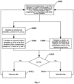
- FIG. 4 is a flowchart of a control method for a refrigerator according to an embodiment of the present invention.
- the control method for a refrigerator may include the following steps: Step S402: detecting an air temperature T 1 in the first chamber 101, a relative air humidity ⁇ 1 in the first chamber 101, an air temperature T 2 in the second chamber 201, and an air temperature T 3 of the inner wall of the second chamber 201.
- a first temperature sensor 300 may be configured to detect the air temperature T 1 in the first chamber 101; a relative humidity sensor 400 is configured to detect the relative air humidity ⁇ 1 in the first chamber 101; a second temperature sensor 500 is configured to detect the air temperature T 2 in the second chamber 201; and a third temperature sensor 600 is configured to detect the air temperature T 3 of the inner wall of the second chamber 201.
- the first temperature sensor 300, the relative humidity sensor 400, the second temperature sensor 500 and the third temperature sensor 600 are all connected to the controller 700, so as to transmit detection signals to the controller 700.
- a temperature of the rear wall 211 of the second chamber 201 is detected, and is taken as the temperature T 3 of the inner wall.
- the inventors have realized that the rear wall 211 of the second chamber 201 is close to the first chamber 101, and can transfer heat with the air in the first chamber 101 through heat conduction; therefore, the temperature of the rear wall 211 is lower than those at other wall surfaces of the second chamber 201, and it is easier to produce condensation. As long as no condensation is produced on the rear wall 211, it can be basically guaranteed that no condensation is produced on the other wall surfaces. Therefore, in this embodiment, only the temperature of the rear wall is detected, thereby better avoiding condensation.
- Step S404 calculating an absolute air humidity ⁇ 1 in the first chamber 101 based on the air temperature T 1 in the first chamber 101 and the relative air humidity ⁇ 1 in the first chamber 101.
- a specific calculation manner for calculating an absolute humidity based on an air temperature and a relative humidity is known by all persons skilled in the art, and belongs to basic knowledge commonly used in the field of refrigeration. Specifically, the absolute humidity can be calculated according to a formula or obtained by querying in a table, which does not need to be described in detail herein.
- Step S406 calculating an expected relative humidity ⁇ 3 of the air in the first chamber 101 when the temperature changes to T 2 based on the absolute air humidity ⁇ 1 and the air temperature T 2 .
- Step S408 calculating a relative air humidity threshold ⁇ 0 based on a correspondence relationship of a dew-point temperature, an ambient temperature and a relative humidity by taking the temperature T 3 of the inner wall of the second chamber 201 as the dew-point temperature and the air temperature T 2 as the ambient temperature.
- the "correspondence relationship of a dew-point temperature, an ambient temperature and a relative humidity" is known by all persons skilled in the art, belongs to basic knowledge commonly used in the field of refrigeration, and specifically includes a computational formula and a relationship table, which do not need to be described in detail herein.
- Step S404 and step S408 are both steps after step S402, but this embodiment does not limit an implementation sequence from step S404 to step S408.
- Step S410 determining whether ⁇ 3 ⁇ 0 is valid. If ⁇ 3 ⁇ 0 is valid, step S412 is implemented; otherwise, step S414 is implemented.
- Step S412 turning on the fan 230.
- a purpose for turning on the fan 230 is to enable the air supply port 212 to supply air to the second chamber 201.
- Step S414 turning off the fan 230.
- a purpose for turning off the fan 230 is to enable the air supply port 212 to stop supplying air to the second chamber 201.
- step S402 is implemented again to form a cycle.
- an open/close state of the air supply port 212 can be adjusted as soon as possible according to temperature and humidity changes of the first chamber 101 and the second chamber 201.
- a distance from a temperature detection point on the rear wall of the second chamber 201 to the air supply port 212 is shorter than or equal to a first preset distance, that is, a distance from the second temperature sensor 500 to the air supply port 212 (namely a lower edge closest to the air supply port 212) is shorter than or equal to the first preset distance.
- a distance from a detection point of the air temperature T 2 to the air supply port 212 is shorter than or equal to a second preset distance, that is, a distance from the third temperature sensor 600 to the air supply port 212 is shorter than or equal to the second preset distance.
- distances from a detection point of the air temperature T 1 and a detection point of the relative air humidity ⁇ 1 to the air supply port 212 are shorter than or equal to a third preset distance, that is, the distances from the first temperature sensor 300 and the relative humidity sensor 400 to the air supply port 212 are shorter than or equal to the third preset distance.
- the first preset distance, the second preset distance and the third preset distance may be the same value or different values ranging from 10 cm to 20 cm.
- the distances from the detection point of the air temperature T 1 in the first chamber 101, the detection point of the relative air humidity ⁇ 1 in the first chamber 101, the temperature detection point on the rear wall of the second chamber 201, and the detection point of the air temperature T 2 of the second chamber 201 to the air supply port 212 are limited to make sure that the above detection points are closer to the air supply port 212, so that temperature and humidity detection is specially performed on an air flow that first enters the air supply port 212 in a later period, thereby achieving more accurate prediction on whether condensation will be produced after the air flow in the first chamber 101 flows into the second chamber 201.
Landscapes
- Engineering & Computer Science (AREA)
- Chemical & Material Sciences (AREA)
- Combustion & Propulsion (AREA)
- Physics & Mathematics (AREA)
- Mechanical Engineering (AREA)
- Thermal Sciences (AREA)
- General Engineering & Computer Science (AREA)
- Cold Air Circulating Systems And Constructional Details In Refrigerators (AREA)
- Devices That Are Associated With Refrigeration Equipment (AREA)
Applications Claiming Priority (2)
| Application Number | Priority Date | Filing Date | Title |
|---|---|---|---|
| CN202010969233.8A CN114183957B (zh) | 2020-09-15 | 2020-09-15 | 冰箱及其控制方法 |
| PCT/CN2021/115636 WO2022057614A1 (fr) | 2020-09-15 | 2021-08-31 | Réfrigérateur et son procédé de commande |
Publications (3)
| Publication Number | Publication Date |
|---|---|
| EP4206573A1 true EP4206573A1 (fr) | 2023-07-05 |
| EP4206573A4 EP4206573A4 (fr) | 2024-01-10 |
| EP4206573B1 EP4206573B1 (fr) | 2024-09-25 |
Family
ID=80539204
Family Applications (1)
| Application Number | Title | Priority Date | Filing Date |
|---|---|---|---|
| EP21868441.3A Active EP4206573B1 (fr) | 2020-09-15 | 2021-08-31 | Réfrigérateur et son procédé de commande |
Country Status (5)
| Country | Link |
|---|---|
| US (1) | US12292222B2 (fr) |
| EP (1) | EP4206573B1 (fr) |
| CN (1) | CN114183957B (fr) |
| AU (1) | AU2021343202B2 (fr) |
| WO (1) | WO2022057614A1 (fr) |
Family Cites Families (19)
| Publication number | Priority date | Publication date | Assignee | Title |
|---|---|---|---|---|
| GB601455A (en) * | 1944-03-29 | 1948-05-06 | Philco Radio & Television Corp | Improvements in or relating to controlled humidity refrigerator |
| JPH07113473B2 (ja) * | 1992-03-03 | 1995-12-06 | 日立冷熱株式会社 | 空気調和機の湿度制御方法 |
| KR0154439B1 (ko) | 1993-11-26 | 1999-01-15 | 김광호 | 냉장고의 제습장치 및 방법 |
| JP3660957B2 (ja) * | 1998-12-29 | 2005-06-15 | ダイキン工業株式会社 | 相対湿度検出装置及びそれを備える空調室内機 |
| CN105222505B (zh) * | 2014-05-30 | 2019-09-17 | 海尔集团技术研发中心 | 加湿室的控制方法及冰箱 |
| CN105526770B (zh) * | 2014-09-29 | 2020-04-24 | 青岛海尔智能技术研发有限公司 | 冰箱内多功能间室的控制方法及冰箱 |
| KR101651334B1 (ko) * | 2014-10-17 | 2016-08-25 | 엘지전자 주식회사 | 냉장고 |
| CN104457102B (zh) | 2014-12-23 | 2017-08-15 | 合肥美的电冰箱有限公司 | 风道结构和冰箱 |
| KR102562149B1 (ko) * | 2015-07-14 | 2023-08-01 | 엘지전자 주식회사 | 냉장고용 도어 및 냉장고 |
| CN105444489A (zh) * | 2015-12-02 | 2016-03-30 | 海信容声(广东)冰箱有限公司 | 一种冰箱 |
| AR103674A1 (es) * | 2016-02-12 | 2017-05-24 | Cerveceria Y Malteria Quilmes S A I C A Y G | Disposición de enfriamiento sectorizado para refrigeradores |
| CN105806010B (zh) * | 2016-05-17 | 2018-07-24 | 合肥美菱股份有限公司 | 一种包含可调温湿度区域的风冷冰箱及其控制方法 |
| CN106765896B (zh) * | 2016-11-29 | 2019-08-16 | 美的集团武汉制冷设备有限公司 | 空调器、加湿控制装置及其湿度控制方法 |
| CN108050745B (zh) | 2017-10-12 | 2020-10-09 | 合肥华凌股份有限公司 | 冰箱及其防凝露控制方法 |
| CN108106298B (zh) * | 2017-11-24 | 2020-05-08 | 青岛海尔股份有限公司 | 冰箱、冰箱的化霜控制装置及方法 |
| US10712037B2 (en) * | 2018-03-29 | 2020-07-14 | Lennox Industries Inc. | Dehumidification technique for heating ventilation and air conditioning systems |
| CN110513957B (zh) * | 2018-05-22 | 2021-05-25 | 重庆海尔制冷电器有限公司 | 冰箱及其控制方法 |
| CN108917271B (zh) | 2018-06-04 | 2020-05-15 | 长虹美菱股份有限公司 | 一种冰箱内置摄像头除露控制方法 |
| CN111296183A (zh) * | 2020-02-02 | 2020-06-19 | 江苏大学 | 一种食用菌菇房环境控制系统及方法 |
-
2020
- 2020-09-15 CN CN202010969233.8A patent/CN114183957B/zh active Active
-
2021
- 2021-08-31 AU AU2021343202A patent/AU2021343202B2/en active Active
- 2021-08-31 US US18/025,274 patent/US12292222B2/en active Active
- 2021-08-31 WO PCT/CN2021/115636 patent/WO2022057614A1/fr not_active Ceased
- 2021-08-31 EP EP21868441.3A patent/EP4206573B1/fr active Active
Also Published As
| Publication number | Publication date |
|---|---|
| CN114183957B (zh) | 2022-09-20 |
| CN114183957A (zh) | 2022-03-15 |
| US12292222B2 (en) | 2025-05-06 |
| WO2022057614A1 (fr) | 2022-03-24 |
| US20230324100A1 (en) | 2023-10-12 |
| EP4206573B1 (fr) | 2024-09-25 |
| AU2021343202A9 (en) | 2024-06-13 |
| AU2021343202B2 (en) | 2024-07-25 |
| AU2021343202A1 (en) | 2023-05-11 |
| EP4206573A4 (fr) | 2024-01-10 |
Similar Documents
| Publication | Publication Date | Title |
|---|---|---|
| CN110332758A (zh) | 冰箱的制冷控制方法与装置 | |
| WO2007091859A1 (fr) | Appareil de refroidissement de réfrigérateur de kimchi et procédé correspondant | |
| CN111536748B (zh) | 一种冰箱及其控制方法 | |
| CN105135783A (zh) | 一种冷藏箱及其控制方法 | |
| CN106225414A (zh) | 冰箱控制方法和电冰箱 | |
| CN111536749B (zh) | 一种冰箱及其控制方法 | |
| EP4206574A1 (fr) | Procédé de commande pour réfrigérateur, et support de stockage informatique | |
| CN115111874A (zh) | 一种冰箱干储控制方法、装置及冰箱 | |
| CN120970196B (zh) | 一种制冷系统及其控制方法、装置、设备及存储介质 | |
| EP4206573B1 (fr) | Réfrigérateur et son procédé de commande | |
| US12292228B2 (en) | Refrigerator | |
| CN111536750B (zh) | 一种冰箱及其控制方法 | |
| CN108775748A (zh) | 一种冷柜及其制冷模块 | |
| US20060137378A1 (en) | Apparatus and method for controlling lamp of refrigerator | |
| US12253294B2 (en) | Refrigerator | |
| CN114562845B (zh) | 冷藏冷冻设备的控制方法与冷藏冷冻设备 | |
| CN110864479A (zh) | 冰箱冷藏室的制冷控制方法和冰箱 | |
| CN113945040B (zh) | 冰箱及其防凝露控制方法、电子设备 | |
| KR101072741B1 (ko) | 김치냉장고 | |
| CN106642883A (zh) | 冰箱及其制冷方法 | |
| KR101189939B1 (ko) | 스탠드형 김치냉장고 및 스탠드형 김치냉장고 제어방법 | |
| CN106610172A (zh) | 冰箱及其制冷方法 | |
| KR20050102451A (ko) | 김치냉장고 | |
| CN104344678A (zh) | 制冷器具及其除湿方法 | |
| KR20050102448A (ko) | 김치냉장고 |
Legal Events
| Date | Code | Title | Description |
|---|---|---|---|
| STAA | Information on the status of an ep patent application or granted ep patent |
Free format text: STATUS: THE INTERNATIONAL PUBLICATION HAS BEEN MADE |
|
| PUAI | Public reference made under article 153(3) epc to a published international application that has entered the european phase |
Free format text: ORIGINAL CODE: 0009012 |
|
| STAA | Information on the status of an ep patent application or granted ep patent |
Free format text: STATUS: REQUEST FOR EXAMINATION WAS MADE |
|
| 17P | Request for examination filed |
Effective date: 20230330 |
|
| AK | Designated contracting states |
Kind code of ref document: A1 Designated state(s): AL AT BE BG CH CY CZ DE DK EE ES FI FR GB GR HR HU IE IS IT LI LT LU LV MC MK MT NL NO PL PT RO RS SE SI SK SM TR |
|
| REG | Reference to a national code |
Ref country code: DE Free format text: PREVIOUS MAIN CLASS: F25D0011020000 Ipc: F25D0021040000 Ref legal event code: R079 Ref document number: 602021019454 Country of ref document: DE |
|
| DAV | Request for validation of the european patent (deleted) | ||
| DAX | Request for extension of the european patent (deleted) | ||
| STAA | Information on the status of an ep patent application or granted ep patent |
Free format text: STATUS: EXAMINATION IS IN PROGRESS |
|
| A4 | Supplementary search report drawn up and despatched |
Effective date: 20231211 |
|
| RIC1 | Information provided on ipc code assigned before grant |
Ipc: F25D 23/02 20060101ALI20231206BHEP Ipc: F25D 21/04 20060101AFI20231206BHEP |
|
| 17Q | First examination report despatched |
Effective date: 20231222 |
|
| GRAP | Despatch of communication of intention to grant a patent |
Free format text: ORIGINAL CODE: EPIDOSNIGR1 |
|
| STAA | Information on the status of an ep patent application or granted ep patent |
Free format text: STATUS: GRANT OF PATENT IS INTENDED |
|
| INTG | Intention to grant announced |
Effective date: 20240605 |
|
| GRAS | Grant fee paid |
Free format text: ORIGINAL CODE: EPIDOSNIGR3 |
|
| GRAA | (expected) grant |
Free format text: ORIGINAL CODE: 0009210 |
|
| STAA | Information on the status of an ep patent application or granted ep patent |
Free format text: STATUS: THE PATENT HAS BEEN GRANTED |
|
| AK | Designated contracting states |
Kind code of ref document: B1 Designated state(s): AL AT BE BG CH CY CZ DE DK EE ES FI FR GB GR HR HU IE IS IT LI LT LU LV MC MK MT NL NO PL PT RO RS SE SI SK SM TR |
|
| REG | Reference to a national code |
Ref country code: GB Ref legal event code: FG4D |
|
| REG | Reference to a national code |
Ref country code: CH Ref legal event code: EP |
|
| REG | Reference to a national code |
Ref country code: DE Ref legal event code: R096 Ref document number: 602021019454 Country of ref document: DE |
|
| REG | Reference to a national code |
Ref country code: IE Ref legal event code: FG4D |
|
| REG | Reference to a national code |
Ref country code: LT Ref legal event code: MG9D |
|
| PG25 | Lapsed in a contracting state [announced via postgrant information from national office to epo] |
Ref country code: NO Free format text: LAPSE BECAUSE OF FAILURE TO SUBMIT A TRANSLATION OF THE DESCRIPTION OR TO PAY THE FEE WITHIN THE PRESCRIBED TIME-LIMIT Effective date: 20241225 |
|
| PG25 | Lapsed in a contracting state [announced via postgrant information from national office to epo] |
Ref country code: GR Free format text: LAPSE BECAUSE OF FAILURE TO SUBMIT A TRANSLATION OF THE DESCRIPTION OR TO PAY THE FEE WITHIN THE PRESCRIBED TIME-LIMIT Effective date: 20241226 Ref country code: FI Free format text: LAPSE BECAUSE OF FAILURE TO SUBMIT A TRANSLATION OF THE DESCRIPTION OR TO PAY THE FEE WITHIN THE PRESCRIBED TIME-LIMIT Effective date: 20240925 |
|
| PG25 | Lapsed in a contracting state [announced via postgrant information from national office to epo] |
Ref country code: BG Free format text: LAPSE BECAUSE OF FAILURE TO SUBMIT A TRANSLATION OF THE DESCRIPTION OR TO PAY THE FEE WITHIN THE PRESCRIBED TIME-LIMIT Effective date: 20240925 |
|
| PG25 | Lapsed in a contracting state [announced via postgrant information from national office to epo] |
Ref country code: LV Free format text: LAPSE BECAUSE OF FAILURE TO SUBMIT A TRANSLATION OF THE DESCRIPTION OR TO PAY THE FEE WITHIN THE PRESCRIBED TIME-LIMIT Effective date: 20240925 |
|
| PG25 | Lapsed in a contracting state [announced via postgrant information from national office to epo] |
Ref country code: RS Free format text: LAPSE BECAUSE OF FAILURE TO SUBMIT A TRANSLATION OF THE DESCRIPTION OR TO PAY THE FEE WITHIN THE PRESCRIBED TIME-LIMIT Effective date: 20241225 |
|
| REG | Reference to a national code |
Ref country code: NL Ref legal event code: MP Effective date: 20240925 |
|
| PG25 | Lapsed in a contracting state [announced via postgrant information from national office to epo] |
Ref country code: RS Free format text: LAPSE BECAUSE OF FAILURE TO SUBMIT A TRANSLATION OF THE DESCRIPTION OR TO PAY THE FEE WITHIN THE PRESCRIBED TIME-LIMIT Effective date: 20241225 Ref country code: NO Free format text: LAPSE BECAUSE OF FAILURE TO SUBMIT A TRANSLATION OF THE DESCRIPTION OR TO PAY THE FEE WITHIN THE PRESCRIBED TIME-LIMIT Effective date: 20241225 Ref country code: LV Free format text: LAPSE BECAUSE OF FAILURE TO SUBMIT A TRANSLATION OF THE DESCRIPTION OR TO PAY THE FEE WITHIN THE PRESCRIBED TIME-LIMIT Effective date: 20240925 Ref country code: GR Free format text: LAPSE BECAUSE OF FAILURE TO SUBMIT A TRANSLATION OF THE DESCRIPTION OR TO PAY THE FEE WITHIN THE PRESCRIBED TIME-LIMIT Effective date: 20241226 Ref country code: FI Free format text: LAPSE BECAUSE OF FAILURE TO SUBMIT A TRANSLATION OF THE DESCRIPTION OR TO PAY THE FEE WITHIN THE PRESCRIBED TIME-LIMIT Effective date: 20240925 Ref country code: BG Free format text: LAPSE BECAUSE OF FAILURE TO SUBMIT A TRANSLATION OF THE DESCRIPTION OR TO PAY THE FEE WITHIN THE PRESCRIBED TIME-LIMIT Effective date: 20240925 |
|
| REG | Reference to a national code |
Ref country code: AT Ref legal event code: MK05 Ref document number: 1726924 Country of ref document: AT Kind code of ref document: T Effective date: 20240925 |
|
| PG25 | Lapsed in a contracting state [announced via postgrant information from national office to epo] |
Ref country code: NL Free format text: LAPSE BECAUSE OF FAILURE TO SUBMIT A TRANSLATION OF THE DESCRIPTION OR TO PAY THE FEE WITHIN THE PRESCRIBED TIME-LIMIT Effective date: 20240925 |
|
| PG25 | Lapsed in a contracting state [announced via postgrant information from national office to epo] |
Ref country code: PT Free format text: LAPSE BECAUSE OF FAILURE TO SUBMIT A TRANSLATION OF THE DESCRIPTION OR TO PAY THE FEE WITHIN THE PRESCRIBED TIME-LIMIT Effective date: 20250127 Ref country code: IS Free format text: LAPSE BECAUSE OF FAILURE TO SUBMIT A TRANSLATION OF THE DESCRIPTION OR TO PAY THE FEE WITHIN THE PRESCRIBED TIME-LIMIT Effective date: 20250125 |
|
| PG25 | Lapsed in a contracting state [announced via postgrant information from national office to epo] |
Ref country code: SM Free format text: LAPSE BECAUSE OF FAILURE TO SUBMIT A TRANSLATION OF THE DESCRIPTION OR TO PAY THE FEE WITHIN THE PRESCRIBED TIME-LIMIT Effective date: 20240925 Ref country code: RO Free format text: LAPSE BECAUSE OF FAILURE TO SUBMIT A TRANSLATION OF THE DESCRIPTION OR TO PAY THE FEE WITHIN THE PRESCRIBED TIME-LIMIT Effective date: 20240925 |
|
| PG25 | Lapsed in a contracting state [announced via postgrant information from national office to epo] |
Ref country code: ES Free format text: LAPSE BECAUSE OF FAILURE TO SUBMIT A TRANSLATION OF THE DESCRIPTION OR TO PAY THE FEE WITHIN THE PRESCRIBED TIME-LIMIT Effective date: 20240925 |
|
| PG25 | Lapsed in a contracting state [announced via postgrant information from national office to epo] |
Ref country code: EE Free format text: LAPSE BECAUSE OF FAILURE TO SUBMIT A TRANSLATION OF THE DESCRIPTION OR TO PAY THE FEE WITHIN THE PRESCRIBED TIME-LIMIT Effective date: 20240925 Ref country code: AT Free format text: LAPSE BECAUSE OF FAILURE TO SUBMIT A TRANSLATION OF THE DESCRIPTION OR TO PAY THE FEE WITHIN THE PRESCRIBED TIME-LIMIT Effective date: 20240925 |
|
| PG25 | Lapsed in a contracting state [announced via postgrant information from national office to epo] |
Ref country code: CZ Free format text: LAPSE BECAUSE OF FAILURE TO SUBMIT A TRANSLATION OF THE DESCRIPTION OR TO PAY THE FEE WITHIN THE PRESCRIBED TIME-LIMIT Effective date: 20240925 Ref country code: PL Free format text: LAPSE BECAUSE OF FAILURE TO SUBMIT A TRANSLATION OF THE DESCRIPTION OR TO PAY THE FEE WITHIN THE PRESCRIBED TIME-LIMIT Effective date: 20240925 |
|
| PG25 | Lapsed in a contracting state [announced via postgrant information from national office to epo] |
Ref country code: IT Free format text: LAPSE BECAUSE OF FAILURE TO SUBMIT A TRANSLATION OF THE DESCRIPTION OR TO PAY THE FEE WITHIN THE PRESCRIBED TIME-LIMIT Effective date: 20240925 Ref country code: SK Free format text: LAPSE BECAUSE OF FAILURE TO SUBMIT A TRANSLATION OF THE DESCRIPTION OR TO PAY THE FEE WITHIN THE PRESCRIBED TIME-LIMIT Effective date: 20240925 |
|
| REG | Reference to a national code |
Ref country code: DE Ref legal event code: R097 Ref document number: 602021019454 Country of ref document: DE |
|
| PG25 | Lapsed in a contracting state [announced via postgrant information from national office to epo] |
Ref country code: DK Free format text: LAPSE BECAUSE OF FAILURE TO SUBMIT A TRANSLATION OF THE DESCRIPTION OR TO PAY THE FEE WITHIN THE PRESCRIBED TIME-LIMIT Effective date: 20240925 |
|
| PLBE | No opposition filed within time limit |
Free format text: ORIGINAL CODE: 0009261 |
|
| STAA | Information on the status of an ep patent application or granted ep patent |
Free format text: STATUS: NO OPPOSITION FILED WITHIN TIME LIMIT |
|
| 26N | No opposition filed |
Effective date: 20250626 |
|
| PG25 | Lapsed in a contracting state [announced via postgrant information from national office to epo] |
Ref country code: SE Free format text: LAPSE BECAUSE OF FAILURE TO SUBMIT A TRANSLATION OF THE DESCRIPTION OR TO PAY THE FEE WITHIN THE PRESCRIBED TIME-LIMIT Effective date: 20240925 |
|
| PGFP | Annual fee paid to national office [announced via postgrant information from national office to epo] |
Ref country code: DE Payment date: 20250812 Year of fee payment: 5 |
|
| PGFP | Annual fee paid to national office [announced via postgrant information from national office to epo] |
Ref country code: GB Payment date: 20250826 Year of fee payment: 5 |
|
| PGFP | Annual fee paid to national office [announced via postgrant information from national office to epo] |
Ref country code: FR Payment date: 20250828 Year of fee payment: 5 |
|
| PG25 | Lapsed in a contracting state [announced via postgrant information from national office to epo] |
Ref country code: HR Free format text: LAPSE BECAUSE OF FAILURE TO SUBMIT A TRANSLATION OF THE DESCRIPTION OR TO PAY THE FEE WITHIN THE PRESCRIBED TIME-LIMIT Effective date: 20240925 |
|
| REG | Reference to a national code |
Ref country code: CH Ref legal event code: H13 Free format text: ST27 STATUS EVENT CODE: U-0-0-H10-H13 (AS PROVIDED BY THE NATIONAL OFFICE) Effective date: 20260324 |
|
| PG25 | Lapsed in a contracting state [announced via postgrant information from national office to epo] |
Ref country code: MC Free format text: LAPSE BECAUSE OF FAILURE TO SUBMIT A TRANSLATION OF THE DESCRIPTION OR TO PAY THE FEE WITHIN THE PRESCRIBED TIME-LIMIT Effective date: 20240925 |
|
| PG25 | Lapsed in a contracting state [announced via postgrant information from national office to epo] |
Ref country code: LU Free format text: LAPSE BECAUSE OF NON-PAYMENT OF DUE FEES Effective date: 20250831 |
|
| PG25 | Lapsed in a contracting state [announced via postgrant information from national office to epo] |
Ref country code: CH Free format text: LAPSE BECAUSE OF NON-PAYMENT OF DUE FEES Effective date: 20250831 |