EP4206603A1 - Pare-balles avec plaques d'impact modulaires - Google Patents
Pare-balles avec plaques d'impact modulaires Download PDFInfo
- Publication number
- EP4206603A1 EP4206603A1 EP22214940.3A EP22214940A EP4206603A1 EP 4206603 A1 EP4206603 A1 EP 4206603A1 EP 22214940 A EP22214940 A EP 22214940A EP 4206603 A1 EP4206603 A1 EP 4206603A1
- Authority
- EP
- European Patent Office
- Prior art keywords
- baffle plates
- bullet trap
- substructure
- funnel
- plates
- Prior art date
- Legal status (The legal status is an assumption and is not a legal conclusion. Google has not performed a legal analysis and makes no representation as to the accuracy of the status listed.)
- Pending
Links
Images


Classifications
-
- F—MECHANICAL ENGINEERING; LIGHTING; HEATING; WEAPONS; BLASTING
- F41—WEAPONS
- F41J—TARGETS; TARGET RANGES; BULLET CATCHERS
- F41J13/00—Bullet catchers
Definitions
- the invention relates to a bullet catcher for shooting ranges for catching bullets.
- the object of the invention is to provide a bullet trap that enables simpler and more cost-effective maintenance.
- the invention in a first aspect, relates to a bullet trap comprising a substructure, several impact plates and at least one deflection.
- the impact plates each have at least one fastening means.
- the baffle plates can be attached to the substructure with the at least one fastening means.
- the substructure is designed in such a way that the baffle plates form one or more funnels, each with two or more funnel walls, when fitted.
- Each hopper wall includes at least two baffles.
- a deflection is arranged behind each funnel.
- the bullet trap is intended to catch bullets on a shooting range and prevent them from ricocheting and damaging people or objects in the vicinity.
- the projectiles caught and collected can be disposed of more easily.
- the projectiles enter the funnel where they hit the impact surface of one of the impact plates.
- the projectiles are deflected by the impact plates into the center of the funnel.
- the deflectors behind the funnels direct the projectiles onto a circular path, where they gradually release their kinetic energy.
- the fastening means are preferably hooks with which the impact plates are hung on the substructure.
- the substructure makes it possible to attach the baffle plates and deflections using a hook system. Due to the baffle plates that can be attached to the substructure using the fastening means, the baffle plates can be made smaller and modular. When worn, only individual deflector plates need to be replaced, which simplifies maintenance of the bullet trap. Furthermore, individual baffle plates can be cheaper than large baffle plates that form the funnel walls in one piece. This makes bullet trap maintenance cheaper.
- each component is no heavier than 40 kg.
- the impact surfaces can be in particular 350 mm by 900 mm. With a weight of 40 kg, the plates can be carried by two people.
- the baffles are formed from sheet steel having a hardness of 500 HBW or greater.
- a hard sheet metal offers a particularly effective protection against deformation of the impact plates by the impact of the projectiles.
- the substructure preferably consists of individual parts.
- a substructure consisting of individual parts has the advantageous effect that the substructure can be assembled easily.
- the attachment means of the baffle plates are designed in such a way that they form different hooks and can be hung on the substructure.
- the hooks are welded to the back of the baffles.
- the bullet trap comprises an intermediate layer of ethylene propylene diene rubber (EPDM) between the fastening means and the substructure.
- EPDM ethylene propylene diene rubber
- the impact plates in the firing channel deform after a certain time
- the impact plates can be reinforced with welded flat steel on a rear side opposite the impact side.
- the rear reinforcement improves the resistance of the impact pads to deformation.
- the impact plates can be arranged partially overlapping one another, for example like roof tiles.
- the bullet trap includes three funnels formed from baffles.
- the width of the funnels is scalable, so the bullet trap can be adapted to the location of the shooting range.
- the bullet trap preferably has only two lateral edges, so that if possible there are no vertical edges in the path of the shot.
- the bullet trap has a collecting device which is arranged below the deflection.
- the collection device can be formed, for example, from a drawer or a conveyor device.
- a conveyor system in particular can catch projectiles from several hoppers arranged side by side or from very wide ones and bring them together at one point for efficient disposal.
- the deflector plates are inclined 20 degrees to a horizontal trajectory of a projectile.
- all edges of the substructure are designed or covered with baffles so that no projectile fragments can be deposited there.
- a single-layer or multi-layer anti-splinter curtain is arranged in front of the bullet trap and in particular in front of the funnel areas.
- the bullet trap is covered all around.
- the escape of lead dust can be almost completely ruled out.
- a fireproof splinter shield is recommended.
- a splinter guard that is suitable as a projection surface for projector applications is particularly preferred.
- the substructure comprises a support element, in particular a steel support, which is mounted on a wall of a building with a base plate and a spacer support.
- a free-standing embodiment of the bullet trap is possible.
- the individual protruding funnel segments are then mounted on the support element, which will later accommodate the baffle plates and deflections.
- the spacing between the individual fields is preferably less than one meter.
- the funnel segments can be aligned horizontally using threaded rods, for example, so that the funnel fields are parallel to one another and not crooked. When the substructure is aligned, the baffle plates are hooked into the structure.
- the bullet trap is mounted in such a way that it can be walked on from behind. Accessibility from the rear allows bullet fragments to be removed and wear parts to be maintained. Preferably, there is a passage about 1 m wide between the bullet trap and the wall behind it, so that the bullet trap can be serviced from behind.
- the bullet trap includes a suction opening from which dust and in particular lead dust can be suctioned off.
- the side walls that can be shot at are covered and lined with anti-recoil material in front of the front funnel area or in front of the anti-splinter curtain.
- Steel is preferably used for the facing and/or the cladding.
- the steel particularly preferably has a hardness of greater than or equal to 500 HBW.
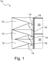
- figure 1 shows a section through a bullet trap 10 with three funnels 12 arranged one above the other.
- the bullet trap 10 is designed to catch bullets that are fired at the bullet trap 10 or a target arranged in front of it.
- "Before" referred to in figure 1 left of bullet trap 10. That is, in the figure, a bullet would hit bullet trap 10 from the left. Behind the funnels 12 deflections 14 and baffles 16 are arranged.
- a projectile hits a funnel 12
- the projectile is deflected in its center and then by the deflectors 14.
- the bullet transfers energy to the deflection and thus becomes slower. It either falls directly, for example from the deflection behind the bottom funnel 12, or indirectly via baffles 16 into a collection device (not shown here).
- the bullet trap is connected to the environment, for example a building wall, via a carrier system 18 . Behind the bullet trap 10 there is a maintenance space 20 through which individual deflector plates can be exchanged or the collecting device can be emptied.
- the maintenance space 20 is preferably 1 m wide.
- figure 2 shows bullet trap 10 figure 1 .
- the trajectories 22 of the projectiles caught by the projectile catcher 10 are indicated in the form of dashes.
- the projectiles which are caught by the funnels 12 are deflected in such a way that they are collected in a collecting device 24 .
- a splinter guard 26 is arranged in front of the central funnel 12 and prevents projectile fragments from bouncing out of the funnel 12 .
- FIG 3 shows a section of the arrangement of baffle plates 28 within a funnel 12.
- the baffle plates 28 are arranged slightly overlapping one another like roof tiles.
- the baffle plates 28 are preferably inclined by approximately 20° with respect to a horizontal line, shown here in dashed lines.
- the impact plates 28 each include one or more fasteners 30 with which they can be attached to a substructure.
- the upper baffle plates 28 each include two fasteners 30.
- the lower baffle plates 28 each include a fastener 30.
- the fastening means 30 are each designed as hooks and figure 4 shown larger.
- the intermediate layer 34 absorbs vibrations caused by the impact of a projectile on a deflector plate 28.
Landscapes
- Engineering & Computer Science (AREA)
- General Engineering & Computer Science (AREA)
- Aiming, Guidance, Guns With A Light Source, Armor, Camouflage, And Targets (AREA)
Applications Claiming Priority (1)
| Application Number | Priority Date | Filing Date | Title |
|---|---|---|---|
| DE102021006365 | 2021-12-28 |
Publications (1)
| Publication Number | Publication Date |
|---|---|
| EP4206603A1 true EP4206603A1 (fr) | 2023-07-05 |
Family
ID=82321180
Family Applications (1)
| Application Number | Title | Priority Date | Filing Date |
|---|---|---|---|
| EP22214940.3A Pending EP4206603A1 (fr) | 2021-12-28 | 2022-12-20 | Pare-balles avec plaques d'impact modulaires |
Country Status (2)
| Country | Link |
|---|---|
| EP (1) | EP4206603A1 (fr) |
| DE (2) | DE202022103144U1 (fr) |
Citations (4)
| Publication number | Priority date | Publication date | Assignee | Title |
|---|---|---|---|---|
| US8602418B1 (en) * | 2010-02-24 | 2013-12-10 | Meggitt Training Systems, Inc. | Projectile trap assembly |
| US8827274B2 (en) * | 2012-05-18 | 2014-09-09 | Bullet Trap, LLC | Projectile containment system |
| US20160187108A1 (en) * | 2014-11-13 | 2016-06-30 | Kenneth Dale Crowe | Bullet trap |
| US10240904B2 (en) * | 2017-03-09 | 2019-03-26 | D5 Iron Works, Inc. | Bullet trap systems and methods of using the same |
-
2022
- 2022-04-13 DE DE202022103144.4U patent/DE202022103144U1/de active Active
- 2022-04-13 DE DE102022108995.9A patent/DE102022108995A1/de active Pending
- 2022-12-20 EP EP22214940.3A patent/EP4206603A1/fr active Pending
Patent Citations (4)
| Publication number | Priority date | Publication date | Assignee | Title |
|---|---|---|---|---|
| US8602418B1 (en) * | 2010-02-24 | 2013-12-10 | Meggitt Training Systems, Inc. | Projectile trap assembly |
| US8827274B2 (en) * | 2012-05-18 | 2014-09-09 | Bullet Trap, LLC | Projectile containment system |
| US20160187108A1 (en) * | 2014-11-13 | 2016-06-30 | Kenneth Dale Crowe | Bullet trap |
| US10240904B2 (en) * | 2017-03-09 | 2019-03-26 | D5 Iron Works, Inc. | Bullet trap systems and methods of using the same |
Also Published As
| Publication number | Publication date |
|---|---|
| DE202022103144U1 (de) | 2022-06-17 |
| DE102022108995A1 (de) | 2023-06-29 |
Similar Documents
| Publication | Publication Date | Title |
|---|---|---|
| DE69418614T2 (de) | Geschossauffanger | |
| EP0076899B1 (fr) | Collecteur de balles | |
| DE202015105489U1 (de) | Modularer Schießstand | |
| EP1029217B1 (fr) | Dispositif d'arret de projectiles | |
| EP4206603A1 (fr) | Pare-balles avec plaques d'impact modulaires | |
| DE202019001557U1 (de) | Geschossfang | |
| EP1990599A1 (fr) | Collecteur de balles, ainsi que procédé et système destinés à leur récupération | |
| DE4022327C2 (de) | Geschoßfangeinrichtung | |
| DE202009014278U1 (de) | Durchschussplatte und Geschossauffangeinrichtung mit einer Durchschussplatte | |
| DE4436060B4 (de) | Geschossfangeinrichtung für Innen- und Außenraum-Einsatz | |
| DE202009015225U1 (de) | Geschossfanganlage | |
| DE19749881A1 (de) | Geschoßfangeinrichtung | |
| EP1413846B1 (fr) | Dispositif arrêtant les plombs d'une cartouche de chasse | |
| DE10221527B4 (de) | Geschossfangeinrichtung und Vorrichtung zur Durchführung von Wartungsarbeiten an derselben | |
| DE4317742A1 (de) | Geschoßfang und Geschoßfangkasten für einen solchen Geschoßfang | |
| EP4034378A1 (fr) | Élément d'habillage de surface conçu pour assurer une protection contre des effets de bombardements et/ou de projectiles et surface recevant des effets de bombardements et/ou de projectiles | |
| DE102021204764A1 (de) | Mehrteilige Tragkonstruktion für eine modulare ballistische Rückprallsicherung | |
| DE20204593U1 (de) | Flächenmaterial für eine Abfangvorrichtung für Schrotschießanlagen | |
| DE19841901B4 (de) | Geschoßfangeinrichtung | |
| DE102021204761A1 (de) | Modulare ballistische Rückprallsicherung | |
| EP1693643A1 (fr) | Système de freinage | |
| DE19613723C1 (de) | Umhauste Anlage für das sportliche und/oder jagdliche und/oder behördliche Schießen mit Schußwaffen | |
| DE102021204763A1 (de) | Modulare ballistische Rückprallsicherung | |
| DE102015006593B4 (de) | Schrotfangeinrichtung für eine Schießanlage | |
| DE102004010636A1 (de) | Geschossfangvorrichtung |
Legal Events
| Date | Code | Title | Description |
|---|---|---|---|
| PUAI | Public reference made under article 153(3) epc to a published international application that has entered the european phase |
Free format text: ORIGINAL CODE: 0009012 |
|
| STAA | Information on the status of an ep patent application or granted ep patent |
Free format text: STATUS: REQUEST FOR EXAMINATION WAS MADE |
|
| 17P | Request for examination filed |
Effective date: 20230525 |
|
| AK | Designated contracting states |
Kind code of ref document: A1 Designated state(s): AL AT BE BG CH CY CZ DE DK EE ES FI FR GB GR HR HU IE IS IT LI LT LU LV MC ME MK MT NL NO PL PT RO RS SE SI SK SM TR |
|
| GRAP | Despatch of communication of intention to grant a patent |
Free format text: ORIGINAL CODE: EPIDOSNIGR1 |
|
| STAA | Information on the status of an ep patent application or granted ep patent |
Free format text: STATUS: GRANT OF PATENT IS INTENDED |
|
| INTG | Intention to grant announced |
Effective date: 20251219 |
|
| GRAS | Grant fee paid |
Free format text: ORIGINAL CODE: EPIDOSNIGR3 |
|
| GRAA | (expected) grant |
Free format text: ORIGINAL CODE: 0009210 |
|
| STAA | Information on the status of an ep patent application or granted ep patent |
Free format text: STATUS: THE PATENT HAS BEEN GRANTED |