EP4206694B1 - Unité de fusion de signaux avec une constante de temps réglable - Google Patents
Unité de fusion de signaux avec une constante de temps réglable Download PDFInfo
- Publication number
- EP4206694B1 EP4206694B1 EP22150040.8A EP22150040A EP4206694B1 EP 4206694 B1 EP4206694 B1 EP 4206694B1 EP 22150040 A EP22150040 A EP 22150040A EP 4206694 B1 EP4206694 B1 EP 4206694B1
- Authority
- EP
- European Patent Office
- Prior art keywords
- merging unit
- frequency
- time constant
- digital
- pass
- Prior art date
- Legal status (The legal status is an assumption and is not a legal conclusion. Google has not performed a legal analysis and makes no representation as to the accuracy of the status listed.)
- Active
Links
Images


Classifications
-
- G—PHYSICS
- G01—MEASURING; TESTING
- G01R—MEASURING ELECTRIC VARIABLES; MEASURING MAGNETIC VARIABLES
- G01R19/00—Arrangements for measuring currents or voltages or for indicating presence or sign thereof
- G01R19/25—Arrangements for measuring currents or voltages or for indicating presence or sign thereof using digital measurement techniques
- G01R19/2506—Arrangements for conditioning or analysing measured signals, e.g. for indicating peak values ; Details concerning sampling, digitizing or waveform capturing
-
- G—PHYSICS
- G01—MEASURING; TESTING
- G01R—MEASURING ELECTRIC VARIABLES; MEASURING MAGNETIC VARIABLES
- G01R19/00—Arrangements for measuring currents or voltages or for indicating presence or sign thereof
- G01R19/25—Arrangements for measuring currents or voltages or for indicating presence or sign thereof using digital measurement techniques
-
- H—ELECTRICITY
- H03—ELECTRONIC CIRCUITRY
- H03M—CODING; DECODING; CODE CONVERSION IN GENERAL
- H03M1/00—Analogue/digital conversion; Digital/analogue conversion
- H03M1/12—Analogue/digital converters
Definitions
- Various example embodiments relate to electrical substation protection and metering systems.
- Merging units are commonly used in electrical substation protection and metering systems for measuring current and voltage signals from sensors and instrument transformers and merging the measured data into a standard digital output format for use by other devices, e.g., for various power system protection application purposes.
- Said current signals may be associated with a plurality of different time constants (or equally a plurality of different high-pass cut-off frequencies). This becomes a problem when sharing measurements between devices which are of different types. Namely, when input time constants (or equally high-pass cut-off frequencies) differ, any current differential protection algorithm may not necessarily see exactly the same current measurements even if they should be equal. Problems may occur especially at transients or when the frequency response does not consist solely of the nominal frequency or does not comprise the nominal frequency at all.
- Document US 5579247 A discloses a ratiometric converter that receives an external sense signal and external reference signal and provides an output signal which is proportional to the sense signal and inversely proportional to the reference signal. Electromagnetic interference and noise coupled onto the sense and reference lines are effectively removed by converting the sense signal to a digital signal and converting the reference signal to a digital signal. The digital sense signal is then filtered through a low pass filter to provide a filtered signal, and similarly, the digital reference signal is filtered through a low pass filter to provide a filtered digital reference signal. A divider circuit then divides the filter digital sense signal by the filter digital reference signal to provide the output signal.
- Some embodiments provide an apparatus, a method, and computer program for enabling a settable time constant or high-pass cut-off frequency.
- circuitry' may refer to one or more or all of the following: (a) hardware-only circuit implementations, such as implementations in only analog and/or digital circuitry, and (b) combinations of hardware circuits and software (and/or firmware), such as (as applicable): (i) a combination of analog and/or digital hardware circuit(s) with software/firmware and (ii) any portions of hardware processor(s) with software, including digital signal processor(s), software, and memory(ies) that work together to cause an apparatus, such as a terminal device or an access node, to perform various functions, and (c) hardware circuit(s) and processor(s), such as a microprocessor(s) or a portion of a microprocessor(s), that requires software (e.g.
- circuitry' also covers an implementation of merely a hardware circuit or processor (or multiple processors) or a portion of a hardware circuit or processor and its (or their) accompanying software and/or firmware.
- the term 'circuitry' also covers, for example and if applicable to the particular claim element, a baseband integrated circuit for an access node or a terminal device or other computing or network device.
- high-pass cut-off frequency as used in the following may be defined as a -3 dB point of a high-pass frequency response (i.e., as the frequency at which the value of high-pass frequency response has lowered from its maximum value by 3 dB).
- merging units are commonly used in electrical substation automation systems for measuring current and voltage signals from sensors and instrument transformers and merging the measured data into a standard digital output format for use by other devices, e.g., for various power system protection application purposes.
- the current inputs of the merging unit possess a high time constant (i.e., possess high-pass characteristics with a low cut-off frequency) as this enables the merging unit to better represent decaying direct current (DC) offset in power network fault situations.
- DC direct current
- IEC61869-6 standard gives the limit of maximum 1 Hz high-pass cutoff frequency, but below 1 Hz it can be any value depending on the implementation.
- IEC 61850 standard aims to enable this.
- the input time constant is typically a result of the hardware design and thus it is not a parameter which can be changed dynamically by the user.
- the embodiments discussed below in detail seek to overcome at least some of the aforementioned problems by implementing a settable time constant (or a settable high-pass cut-off frequency) in the merging unit.
- This settable time constant or high-pass cut-off frequency would enable the user to match the time constants between used input hardware (if they are of different types) so as to, e.g., improve differential protection accuracy.
- FIG. 1 illustrates an exemplary system 100 according to an embodiment.
- the system 100 may be called a substation automation system (SAS), a power system or a substation protection and metering system.
- SAS substation automation system
- the system 100 comprises a plurality of measurement devices 111, 112, 113, a merging unit 101 and one or more network devices 121, 122. Any of the illustrated elements may be logical elements implemented as hardware or software or a combination thereof.
- Said plurality of measurements devices 111, 112, 113 are devices configured to produce measurement data.
- Said measurement data may comprise analog and/or digital voltage measurements and/or analog and/or digital current measurements.
- the digital voltage and/or current measurement data may be outputted by the plurality of measurement devices 111, 112, 113 in various different formats. At least some of said different formats may be associated with different time constants (or equally with different high-pass cut-off frequencies).
- Said plurality of measurement devices 111, 112, 113 may comprise one or more devices of any of the following types: an instrument transformer (IT), an electronic instrument transformer (EIT) and a low power instrument transformer (LPIT) (or other sensing device).
- a LPIT (or said other sending device) may comprise a sensor (e.g., a voltage sensor or a current sensor).
- Said plurality of measurement devices 111, 112, 113 may correspond to primary equipment in a switchgear of the system 100.
- Said plurality of measurements devices 111, 112, 113 may provide analog output signals to the merging unit 101.
- At least some of said plurality of measurements devices 111, 112, 113 may comprise built-in analog-to-digital converters and data formatting means for generating sampled measured value (SMV) signals.
- SMV signals (or SMV messages) are digital signals comprising measurement data and having a pre-defined SV message format as defined in IEC 61850-9-2.
- the merging unit 101 is configured to receive current and/or voltage signals from said plurality of measurements devices 111, 112, 113, merge the measured data into a standard digital output format and output at least one output signal having said standard digital output format to other devices (namely, here to the network devices 121, 122).
- the merging unit 101 comprises a plurality of interfaces 102, digital processing means 103 and at least one memory 104.
- the plurality of interfaces 102 comprise at least a plurality of input interfaces 105 and one or more output interfaces 106.
- the plurality of input interfaces 105 comprise a plurality of input interfaces for reception of input signals (e.g., analog input signals) from the plurality of measurement devices 111, 112, 113.
- the merging unit 101 and the plurality of measurement devices 111, 112, 113 may be connected specifically via one or more wired connections (e.g., one or more cables).
- the plurality of input interfaces 105 for reception of input signals from the plurality of measurement devices 111, 112, 113 may use the IEC 61850-8-1 GOOSE (Generic Object Oriented Substation Event) profile.
- the one or more input interfaces 105 may also comprise at least one user interface for reception of user inputs provided by a user via at least one user input device of the merging unit 101 (e.g., a keyboard, a mouse, a trackball, a set of dedicated buttons and/or control dials, a touch pad and/or a touchscreen).
- at least one user input device of the merging unit 101 e.g., a keyboard, a mouse, a trackball, a set of dedicated buttons and/or control dials, a touch pad and/or a touchscreen.
- At least one of the one or more input interfaces for reception of input signals from the plurality of measurement devices 111, 112, 113 corresponds to an analog-to-digital input interfaces configured to convert a received analog input signal to a digital input signal.
- the merging unit 101 may comprise analog-to-digital conversion means for converting one or more analog input signals of the merging unit 101 to one or more (corresponding) digital input signals which may be processed (e.g., filtered and merged) by the digital processing means 103.
- the one or more output interfaces 105 comprise at least one or more output interfaces for outputting one or more merged (digital) output signals (i.e., a homogeneously defined digital data stream created from measured data and having a standardized format) produced by the merging unit based on the input signal(s) received via the plurality of input interfaces 105 to one or more network devices 121, 122.
- the output signals outputted via the one or more output interfaces 105 may have a pre-defined format. Said pre-defined format may specifically a format defined in a standard such as IEC 61850-9-2.
- the merging unit 101 and the one or more network devices 121, 122 may be connected specifically via one or more wired connections (e.g., one or more fiber optic connections and/or one or more electrical cables).
- the one or more interfaces 102 may further comprise one or more communication interfaces (being input/output interfaces) for realizing communication connectivity according to one or more communication protocols via one or more (wired and/or wireless) communication links and/or via one or more (wired and/or wireless) communication networks.
- the one or more communication interfaces 910 may comprise, for example, interfaces providing a connection to the Internet and/or a core network of a wireless communications network.
- the one or more communication interface 910 may provide the apparatus with communication capabilities to communicate in a cellular communication system and enable communication between user devices (terminal devices) and different network nodes or elements and/or a communication interface to enable communication between different network nodes or elements, for example.
- the one or more communication interfaces may comprise standard well-known components such as an amplifier, filter, frequency-converter, (de)modulator, and encoder/decoder circuitries, controlled by the corresponding controlling units, and one or more antennas.
- the one or more communication interfaces may comprise one or more (optical or galvanic) Ethernet network interfaces.
- the digital processing means 103 may be configured to implementing the functionalities of the merging unit 101 according to embodiments to be discussed below in detail.
- the digital processing means are configured at least to high-pass filter, using one or more digital filters, at least one of the plurality of input signals received via the one or more input interfaces 105 so as to lower a time constant associated with said at least one of the one or more input signals for matching a target time constant or so as to raise a high-pass cut-off frequency associated with said one of the one or more input signals to match a target high-pass cut-off frequency and to merge, following the high-pass filtering, the one or more inputs signals into an output signal having a pre-defined output format.
- the digital processing means 103 may comprise or correspond to digital processing circuitry.
- the digital processing means 103 may be communicatively connected to the at least one memory 104.
- the digital processing means 103 may comprise the at least one memory 104 (not shown in Figure 1 ).
- Some example digital processing means for carrying out the processes according to embodiments may include at least one of the following: detector, processor (including dual-core and multiple-core processors), digital signal processor, controller, receiver, transmitter, encoder, decoder, memory, RAM, ROM, software, firmware, display, user interface, display circuitry, user interface circuitry, user interface software, display software, circuit, antenna, antenna circuitry, and circuitry.
- the digital processing means 103 may comprise, for example, one or more field-programmable gate arrays (FPGAs) and/or one or more application-specific integrated circuits (ASICs). In some such embodiments, at least one of the one or more FPGAs and/or one or more ASICs may be configured specifically to implement the filtering functionalities according to embodiments.
- FPGAs field-programmable gate arrays
- ASICs application-specific integrated circuits
- the digital processing means 103 may comprise at least one processor (e.g., a microprocessor and/or a digital signal processor).
- said at least one memory 104 may comprise one or more algorithms, such as a computer program code (software).
- the at least one memory 104 and computer program code may be configured, with the at least one processor 103, to cause the performing of the digital processing means 104 (or of the merging unit 101) according to embodiments.
- Said at least one memory 104 may also comprise at least one database.
- the at least one memory 104 may be implemented using any suitable data storage technology, such as semiconductor based memory devices, flash memory, magnetic memory devices and systems, optical memory devices and systems, fixed memory and removable memory.
- Said at least one memory 104 may store a (current) value of a target time constant and/or a target high-pass cut-off frequency. Additionally or alternatively, said at least one memory 104 may store filter settings of one or more digital filters used in embodiments.
- said at least one memory 104 may store a lookup table.
- the lookup table may define a plurality of sets of filter settings of one or more digital filters (usable by the digital processing means 103 of the merging unit 101) for achieving plurality of target time constants and/or target high-pass cut-off frequencies.
- the lookup table may define, e.g., a set of filters for handling cutoff frequencies from 0.0 Hz to 1.0 Hz with 0.1 Hz or 0.05 Hz frequency step. In case of a nonlinear input with, e.g., 0.5 Hz cutoff frequency, the inverse filter of this is the same in each case only the frequencies between 0.5Hz and 1.0 Hz need a lookup table with filter parameters.
- a filter design algorithm may be maintained in said at least one memory.
- the filter design algorithm may be configured to output a set of filter settings based on an input of a target time constant or a target high-pass cut-off frequency.
- the one or more output signals outputted via the one or more output interfaces 105 may be specifically fed to the one or more network devices 121, 122 (in the illustrated example, two network devices).
- the one or more network devices 121, 122 are, in general, (computing) devices supporting network operation.
- the plurality of network devices 121, 122 may be equally called SMV subscribers.
- Said one or more network devices 121, 122 may comprise one or more devices of any of the following types: a protective (or protection) device, a power quality device and a (power) measurement and/or metering device other than a power quality device.
- the merging unit 101 may be, for example, a built-in merging unit of an instrument transformer as defined in, e.g., IEC 61869 or a stand alone merging unit (SAMU) as defined in IEC 61869-13 .
- SAMU stand alone merging unit
- Figure 1 presents a simplified view of a system 100 and specifically of a merging unit 101 therein.
- the system 100 and the merging unit 101 may comprise one or more further elements commonly found in substation protection and metering systems, substation automation systems or power systems and/or in merging units.
- the merging unit may comprise synchronization means (e.g., an integrated clock or an interface enabling synchronization) for synchronization of the input signals received by it and power supplying means.
- the synchronization may employ, e.g., IEEE 1588 standard.
- the merging unit 101 may comprise a built-in secondary converter or both a built-in primary converter and a built-in secondary converter.
- Figure 2 illustrates a process according to embodiments for performing filtering and merging of measured input data.
- the process may be carried out by the merging unit 101 of Figure 1 or a part thereof (namely, at least by the digital processing means 103).
- the entity carrying out the process is called a merging unit merely for simplicity of description.
- the merging unit receives, in block 201, a plurality of input signals characterizing currents, and optionally one or more voltages, measured by a plurality of measurement devices of a substation automation system via one or more input interfaces of the merging unit.
- the one or more input interfaces may specifically comprise a plurality of input interfaces for connecting to the plurality of measurement devices as discussed in connection with Figure 1 .
- the plurality of input signals comprise signals characterizing a current (i.e., input current signals).
- each or at least one of the plurality of input signals received from the plurality of measurement devices may specifically be analog input signals.
- the receiving in block 201 comprises also converting the received plurality of analog input signals to a plurality of digital input signals. The following steps of the process are then carried out for said plurality of digital input signals.
- the merging unit high-pass filters, in block 202, using one or more digital filters, at least one of the plurality of input signals for either lowering a time constant associated with said at least one of the one or more input signals to match a target time constant or for raising a high-pass cut-off frequency associated with said one of the one or more input signals (being an effectively equal operation to lowering the time constant) to match a target high-pass cut-off frequency.
- the merging unit effectively worsens the frequency response of some of the input signals so as to form a modified set of input signals where all the input signals (or at least all current input signals) have the same frequency behavior and are thus compatible with each other. This may be beneficial, for example, in view of implementation of SMV based differential protection schemes. It should be noted that the merging unit hardware may place a limit on the minimum high-pass cutoff frequency but not on the maximum high-pass cut-off frequency which enables the aforementioned operation.
- Said target time constant or target high-pass cut-off frequency may be pre-defined. In other words, a value of said target time constant or target high-pass cut-off frequency may be stored in a memory of the merging unit. Said target time constant or target high-pass cut-off frequency may be a (tunable) setting of the merging unit. If the merging unit is a built-in merging unit of an instrument transformer as defined, e.g., in IEC 61869, this (tunable) setting of the merging unit may specifically control the frequency responses of the primary and secondary converters of the merging unit.
- this (tunable) setting of the merging unit may specifically control the frequency response of the current input of the stand alone merging unit. See discussion in connection with Figure 2 for detailed description of the tuning operation.
- Said at least one of the plurality of input signals comprise or consist of one or more current signals (or specifically one or more analog current signals).
- the filtering in block 202 may be applied specifically to any current input signals received in block 201.
- said at least one of the plurality of input signals may comprise or consist of one or more voltage signals (or one or more analog voltage signals).
- said at least one of the plurality of input signals may be specifically selected by the merging unit to be (current) signals whose time constant fails to exceed the target time constant or whose high-pass cut-off frequency falls below the target high-pass cut-off frequency.
- the one or more digital filters may be such that they simulate the behavior of a current transformer. Such behavior corresponds to a 1st order analog high-pass RC filter in the analog domain while, in the digital domain, it may be achieved using an infinite impulse response (IIR) filter.
- the sampling frequency used in the digital filtering may, e.g., be equal to the output of the analog-to-digital converter (ADC) of the merging unit and/or measurement device(s).
- the IIR filter may be either a high-pass filter with the target time constant or high-pass cut-off frequency (if the input hardware frequency response exhibits no high-pass behavior) or a combination of an inverse filter (inverse of the input hardware frequency response) and a high-pass filter with the target time constant or high-pass cut-off frequency, as will be described below in more detail.
- the filter settings of the one or more digital filters may be determined based on the at least one of the one or more input signals and a lookup table or a filter design algorithm maintained in a memory of the merging unit.
- the lookup table may define a plurality of sets of filter settings of the one or more digital filters for achieving plurality of target time constants and/or target high-pass cut-off frequencies and/or the filter design algorithm may be configured to output a set of filter settings based on an input of the target time constant or the target high-pass cut-off frequency.
- Said target time constant and/or target high-pass cut-off frequency may have been defined (before the high-pass filtering) by a user input.
- Said user input may have been received either via a user input interface providing a connection to at least one user input device of the merging unit or via a communication interface providing a connection over one or more (wired and/or wireless) communication links and/or networks.
- the merging unit merges, in block 203, the plurality of input signals into an output signal having a pre-defined output format. It should be emphasized that the merging in block 203 is performed following the high-pass filtering, i.e., for a plurality of (digital) input signals comprising at least one high-pass filtered signal.
- the pre-defined format of the output signal may be a standard-based format such as a format defined in IEC 61850-9-2 for an output of a merging unit.
- the merging unit outputs, in block 204, the output signal via one or more output interfaces.
- the output signal may be outputted specifically to a network device (e.g., a protective device).
- a plurality of (identical) output signals may be outputted to a plurality of network devices.
- the merging unit may maintain in a memory of the merging unit information on value(s) of a target and/or a target high-pass cut-off frequency. It would be beneficial if said value(s) could be changed by the user, i.e., that it would be defined as user-defined setting of the merging unit.
- Figure 2 illustrates a process according to embodiments for implementing such functionality. The process may be carried out by the merging unit 101 of Figure 1 or a part thereof (namely, at least by the digital processing means 103). In the following, the entity carrying out the process is called a merging unit merely for simplicity of description.
- the merging unit is assumed, in block 301, to maintain, in at least one memory, information on the target time constant and/or the target high-pass cut-off frequency. Additionally or alternatively, the merging unit may maintain in said at least one memory information on filter settings of the one or more digital filters (or some of them) for implementing the target time constant and/or the target high-pass cut-off frequency.
- the one or more digital filters may comprise specifically IIR filters.
- the filter settings for a given IIR digital filter may comprise, e.g., feedforward filter coefficients, feedback filter coefficients, feedforward filter order and/or feedbackward filter order.
- the merging unit receives, in block 302, a user input (or a signal comprising information on a user input) via a user input interface or a communication interface of the merging unit.
- the merging unit may comprise at least one user input interface for receiving inputs provided by user via at least one user input device of the merging unit (or connected thereto) and/or at least one communication interface for receiving signals over at least one communication link and/or network.
- the merging unit may check whether the value of the target time constant and/or the target high-pass cut-off frequency received in block 302 is different from a corresponding value maintained in said at least one memory and proceed further in the process only if the received value is a new value not maintained in said at least one memory.
- the merging unit stores, in block 303, a received value of the target time constant or target high-pass cut-off frequency to said at least one memory.
- the merging unit updates the current value of the target time constant or target high-pass cut-off frequency maintained in said at least one memory to match the received (user-defined) value.
- the merging unit adjusts, in block 304, filter settings of the one or more digital filters (or some of them) based on the target time constant or the target high-pass cut-off frequency defined by the user input.
- the adjusting in block 304 may be carried out in response to the receiving in block 302 or subsequently, e.g., in response to receiving input signals for merging which require filtering (as discussed in connection with Figure 1 ).
- the filter properties of high-pass digital (IIR) filter(s) defined according to the target time constant and/or the target high-pass cut-off frequency may be adjusted in block 304 (see discussion below in connection with Figure 4 ).
- the adjusting may be carried out, as described also above, based on a lookup table or a filter design algorithm maintained in said at least one memory.
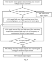
- Figure 4 illustrates another, more detailed process according to embodiments for performing filtering and merging of measured input data.
- the process may be carried out by the merging unit 101 of Figure 1 or a part thereof (namely, at least by the digital processing means 103). Any of the features discussed in connection with Figure 2 may be applied to the process of Figure 4 .
- the entity carrying out the process is called a merging unit merely for simplicity of description.
- the process of Figure 4 may be preceded by the process of Figure 3 .
- block 401 may correspond fully to block 201 of Figure 2 .
- the operation of the merging unit depends on the current operating mode (or a current operating setting) of the merging unit.
- Two different operating modes may be defined for filtering different types of input signals, e.g., as follows: a first operating mode may be for filtering input signals exhibiting no high-pass behavior and a second operating mode may be for filtering input signals exhibiting high-pass behavior failing to meet the target time constant or the target high-pass cut-off frequency.
- Information on the current operating mode may be maintained in at least one memory of the merging unit.
- the operating mode may be a setting of the merging unit which is settable by a user (e.g., via a user input interface or remotely via a communication interface).
- the setting of the operating mode may be carried out in a similar or analogous manner as discussed in connection with Figure 3 for setting the target time constant and/or the target high-pass cut-off frequency for the plurality of input signals (though, obviously, block 304 of Figure 3 is not applicable in this case).
- high-pass behavior of the input signal may depend not only on the input signal itself but also on the high-pass properties of a given (analog) input interface of the merging unit.
- the merging unit applies, in block 403, a high-pass digital (IIR) filter matching the target time constant and/or the target high-pass cut-off frequency to the input signal.
- IIR high-pass digital
- the filter settings of the high-pass digital (IIR) filter may have been determined previously and may be maintained in the at least one memory of the merging unit.
- the input signal in question is modified to correspond to the target time constant and/or the target high-pass cut-off frequency.
- the target time constant and/or the target high-pass cut-off frequency may be defined as discussed in connection with Figure 1 (e.g., it may be defined via a user input).
- the merging unit applies, in block 404, an inverse digital (IIR) filter and a high-pass digital filter matching the target time constant and/or the target high-pass cut-off frequency consecutively (i.e., one after another) to the input signal.
- the inverse digital filter signal may be defined to correspond to an inverse filter for (assumed) high-pass behavior of the input signal (i.e., an inverse filter for a frequency response of the input signal).
- the merging unit may apply, in block 404, a digital (IIR) filter corresponding to a combination of the inverse and high-pass digital filters (e.g., derived as a product of the frequency response of the inverse and high-pass digital filters) to the input signal.
- IIR digital
- the input signal has, following block 404, the same form in both cases. In either case, the input signal in question is modified to increase the high-pass cut-off frequency (or equally to lower the time constant).
- the merging unit may, obviously, also have a third operating mode where no filtering is carried out for the input signal.
- the merging unit checks, in block 405, whether all of the plurality of input signals have been covered (i.e., whether the process of blocks 402 to 404 has been carried out for all input signals). If this is not the case, the merging unit selects, in block 408, the next input signal of the plurality of input signal for analysis and potential filtering and repeats actions pertaining to blocks 402, 403, 405 or 402, 404, 405. If all of the plurality of input signals have been covered in block 405, the merging unit proceeds to blocks 406, 407. Said blocks 406, 407 may correspond fully to blocks 203, 204 of Figure 2 .
- actions relating to blocks 402 to 408 may be carried out only for one or more current input signals of the plurality of input signals received in block 401.
- only one of the first and second operating modes may be defined.
- Embodiments as described may also be carried out in the form of a computer process defined by a computer program or portions thereof. Embodiments of the methods described in connection with Figures 2 to 4 may be carried out by executing at least one portion of a computer program comprising corresponding instructions.
- the computer program may be provided as a computer readable medium comprising program instructions stored thereon or as a non-transitory computer readable medium comprising program instructions stored thereon.
- the computer program may be in source code form, object code form, or in some intermediate form, and it may be stored in some sort of carrier, which may be any entity or device capable of carrying the program.
- the computer program may be stored on a computer program distribution medium readable by a computer or a processor.
- the computer program medium may be, for example but not limited to, a record medium, computer memory, read-only memory, electrical carrier signal, telecommunications signal, and software distribution package, for example.
- the computer program medium may be a non-transitory medium. Coding of software for carrying out the embodiments as shown and described is well within the scope of a person of ordinary skill in the art.
Landscapes
- Physics & Mathematics (AREA)
- General Physics & Mathematics (AREA)
- Engineering & Computer Science (AREA)
- Theoretical Computer Science (AREA)
- Emergency Protection Circuit Devices (AREA)
Claims (14)
- Unité de fusion pour un système d'automatisation de sous-station, l'unité de fusion (101) comprenant :une ou plusieurs interfaces d'entrée (105) pour recevoir, en provenance d'une pluralité de dispositifs de mesure (111, 112, 113) du système d'automatisation de sous-station, une pluralité de signaux d'entrée comprenant des signaux de courant caractérisant des courants mesurés par la pluralité de dispositifs de mesure (111, 112, 113) et, éventuellement, un ou plusieurs signaux de tension caractérisant une ou plusieurs tensions mesurées par la pluralité de dispositifs de mesure (111, 112, 113) ;des moyens de traitement numérique (103) pour effectuer un filtrage passe-haut, en utilisant un ou plusieurs filtres numériques, d'au moins un signal de courant parmi les signaux de courant pour abaisser une constante de temps associée audit au moins un signal de courant pour la faire correspondre à une constante de temps cible ou pour augmenter une fréquence de coupure passe-haut associée audit au moins un signal de courant pour la faire correspondre à une fréquence de coupure passe-haut cible afin de rendre les signaux de courant compatibles entre eux, etfusionner, après le filtrage passe-haut, la pluralité de signaux d'entrée en un signal de sortie ayant un format de sortie prédéfini ; etune ou plusieurs interfaces de sortie (106) pour émettre le signal de sortie.
- Unité de fusion selon la revendication 1, dans laquelle les moyens de traitement numérique (103) sont en outre configurés pour sélectionner ledit au moins un signal de courant en tant que signal ou signaux associés à une constante de temps qui ne dépasse pas la constante de temps cible ou à une fréquence de coupure passe-haut qui tombe en dessous de la fréquence de coupure passe-haut cible.
- Unité de fusion selon l'une quelconque des revendications précédentes, dans laquelle les moyens de traitement numérique (103) sont configurés pour :
tenir à jour, dans au moins une mémoire (104), des informations concernant la constante de temps cible et/ou la fréquence de coupure passe-haut cible et/ou des informations concernant les paramètres de filtre des un ou plusieurs filtres numériques pour la mise en œuvre de la constante de temps cible et/ou de la fréquence de coupure passe-haut cible. - Unité de fusion selon l'une quelconque des revendications précédentes, comprenant en outre :au moins une interface d'entrée utilisateur pour recevoir, via au moins un dispositif d'entrée utilisateur, une entrée utilisateur définissant la constante de temps cible et/ou la fréquence de coupure passe-haut cible pour la pluralité de signaux d'entrée ; et/ouau moins une interface de communication pour recevoir, sur une liaison ou un réseau de communication, un signal définissant une entrée utilisateur définissant la constante de temps cible et/ou la fréquence de coupure passe-haut cible pour la pluralité de signaux d'entrée, les moyens de traitement numérique (103) étant en outre configurés pouren réponse à la réception d'une entrée utilisateur définissant la constante de temps cible ou la fréquence de coupure passe-haut cible via ladite au moins une interface d'entrée utilisateur ou ladite au moins une interface de communication, stocker une valeur reçue de la constante de temps cible ou de la fréquence de coupure passe-haut cible dans ladite au moins une mémoire (104) ; etajuster les paramètres de filtre de l'au moins un des un ou plusieurs filtres numériques sur la base de la constante de temps cible ou de la fréquence de coupure passe-haut cible définie par l'entrée utilisateur.
- Unité de fusion selon la revendication 4, dans laquelle les moyens de traitement numérique (103) sont configurés pourtenir à jour, dans ladite au moins une mémoire (104), une table de correspondance définissant une pluralité d'ensembles de paramètres de filtre des un ou plusieurs filtres numériques pour obtenir une pluralité de constantes de temps cibles et/ou de fréquences de coupure passe-haut cibles ; eteffectuer l'ajustement des paramètres de filtre dudit au moins un des un ou plusieurs filtres numériques sur la base de la table de correspondance.
- Unité de fusion selon l'une quelconque des revendications précédentes, dans laquelle les moyens de traitement numérique (103) sont configurés pour exécuter le filtrage passe-haut, pour chacun de la pluralité de signaux d'entrée, par les opérations suivantes :si l'unité de fusion (101) est actuellement configurée pour fonctionner en utilisant un premier mode de fonctionnement pour filtrer des signaux d'entrée n'ayant pas de comportement passe-haut, application d'un filtre numérique passe-haut correspondant à la constante de temps cible et/ou la fréquence de coupure passe-haut cible au signal d'entrée ; etsi l'unité de fusion (101) est actuellement configurée pour fonctionner en utilisant un deuxième mode de fonctionnement pour filtrer des signaux d'entrée ayant un comportement passe-haut ne satisfaisant pas à la constante de temps cible ou à la fréquence de coupure passe-haut cible, application d'un filtre numérique inverse et d'un filtre numérique passe-haut correspondant à la constante de temps cible et/ou la fréquence de coupure passe-haut cible, de manière consécutive, ou d'un filtre numérique correspondant à une combinaison des filtres numérique inverse et passe-haut au signal d'entrée, le filtre numérique inverse correspondant à un filtre inverse pour une réponse fréquentielle du signal d'entrée.
- Unité de fusion selon l'une quelconque des revendications précédentes, dans laquelle la ou les interfaces d'entrée (105) ou une partie de celle-ci comprennent des interfaces d'entrée analogique-numérique pour convertir un signal d'entrée analogique reçu en un signal d'entrée numérique.
- Unité de fusion selon l'une quelconque des revendications précédentes, dans laquelle la pluralité de signaux d'entrée sont des signaux d'entrée analogiques, l'unité de fusion (101) comprenant en outre :
des moyens de conversation analogique-numérique pour convertir la pluralité de signaux d'entrée en signaux numériques pour leur traitement par les moyens de traitement numérique (103). - Unité de fusion selon l'une quelconque des revendications précédentes, dans laquelle le ou les filtres numériques sont des filtres à réponse impulsionnelle infinie.
- Unité de fusion selon l'une quelconque des revendications précédentes, dans laquelle le format prédéfini du signal de sortie est un format normalisé selon la norme IEC 61850-9-2.
- Unité de fusion selon l'une quelconque des revendications précédentes, dans laquelle les moyens de traitement numérique (103) comprennent un ou plusieurs réseaux de portes programmables, FPGA, et/ou un ou plusieurs circuits intégrés spécifiques à une application, ASIC.
- Unité de fusion selon l'une quelconque des revendications précédentes, dans laquelle les moyens de traitement numérique (103) comprennent :au moins un processeur ; etau moins une mémoire incluant un code de programme informatique, l'au moins une mémoire et le code de programme informatique étant configurés, avec l'au moins un processeur, pour permettre l'exécution des moyens de traitement numérique (103).
- Procédé comprenant :la réception, dans une unité de fusion (101) pour un système d'automatisation de sous-station, en provenance d'une pluralité de dispositifs de mesure (111, 112, 113) du système d'automatisation de sous-station, d'une pluralité de signaux d'entrée comprenant des signaux de courant caractérisant des courants mesurés par la pluralité de dispositifs de mesure (111, 112, 113) et, éventuellement, un ou plusieurs signaux de tension caractérisant une ou plusieurs tensions mesurées par la pluralité de dispositifs de mesure (111, 112, 113) ;le filtrage passe-haut, par l'unité de fusion (101), en utilisant un ou plusieurs filtres numériques, d'au moins un signal de courant parmi les signaux de courant pour abaisser une constante de temps associée audit au moins un signal de courant pour la faire correspondre à une constante de temps cible ou pour augmenter une fréquence de coupure passe-haut associée audit au moins un signal de courant pour la faire correspondre à une fréquence de coupure passe-haut cible afin de rendre les signaux de courant compatibles entre eux ;la fusion, par l'unité de fusion (101), après le filtrage passe-haut, de la pluralité de signaux d'entrée en un signal de sortie ayant un format de sortie prédéfini ; etl'émission, par l'unité de fusion (101), du signal de sortie.
- Programme informatique comprenant des instructions pour amener une unité de fusion (101) pour un système d'automatisation de sous-station à exécuter au moins les opérations suivantes :réception, en provenance d'une pluralité de dispositifs de mesure (111, 112, 113) du système d'automatisation de sous-station, d'une pluralité de signaux d'entrée comprenant des signaux de courant caractérisant des courants mesurés par la pluralité de dispositifs de mesure (111, 112, 113) et, éventuellement, un ou plusieurs signaux de tension caractérisant une ou plusieurs tensions mesurées par la pluralité de dispositifs de mesure (111, 112, 113) ;filtrage passe-haut, en utilisant un ou plusieurs filtres numériques, d'au moins un signal de courant parmi les signaux de courant pour abaisser une constante de temps associée audit au moins un signal de courant pour la faire correspondre à une constante de temps cible ou pour augmenter une fréquence de coupure passe-haut associée audit au moins un signal de courant pour la faire correspondre à une fréquence de coupure passe-haut cible afin de rendre les signaux de courant compatibles entre eux ;fusionner, après le filtrage passe-haut, la pluralité de signaux d'entrée en un signal de sortie ayant un format de sortie prédéfini ; etémission du signal de sortie.
Priority Applications (3)
| Application Number | Priority Date | Filing Date | Title |
|---|---|---|---|
| EP22150040.8A EP4206694B1 (fr) | 2022-01-03 | 2022-01-03 | Unité de fusion de signaux avec une constante de temps réglable |
| CN202211655066.5A CN116413506B (zh) | 2022-01-03 | 2022-12-22 | 具有可设置的时间常数的合并单元 |
| US18/147,886 US12540956B2 (en) | 2022-01-03 | 2022-12-29 | Merging unit with a settable time constant |
Applications Claiming Priority (1)
| Application Number | Priority Date | Filing Date | Title |
|---|---|---|---|
| EP22150040.8A EP4206694B1 (fr) | 2022-01-03 | 2022-01-03 | Unité de fusion de signaux avec une constante de temps réglable |
Publications (3)
| Publication Number | Publication Date |
|---|---|
| EP4206694A1 EP4206694A1 (fr) | 2023-07-05 |
| EP4206694C0 EP4206694C0 (fr) | 2025-06-11 |
| EP4206694B1 true EP4206694B1 (fr) | 2025-06-11 |
Family
ID=79185839
Family Applications (1)
| Application Number | Title | Priority Date | Filing Date |
|---|---|---|---|
| EP22150040.8A Active EP4206694B1 (fr) | 2022-01-03 | 2022-01-03 | Unité de fusion de signaux avec une constante de temps réglable |
Country Status (3)
| Country | Link |
|---|---|
| US (1) | US12540956B2 (fr) |
| EP (1) | EP4206694B1 (fr) |
| CN (1) | CN116413506B (fr) |
Family Cites Families (10)
| Publication number | Priority date | Publication date | Assignee | Title |
|---|---|---|---|---|
| JPH077906B2 (ja) * | 1986-11-21 | 1995-01-30 | 日本電気株式会社 | オフセツトキヤンセル回路 |
| GB2252829B (en) * | 1991-02-15 | 1994-10-19 | Crystal Semiconductor Corp | Method and apparatus for decreasing the interference and noise sensitivity of a ratiometric converter type of circuit |
| US20060028197A1 (en) * | 2004-08-05 | 2006-02-09 | Microchip Technology Incorporated | Direct current offset cancellation and phase equalization for power metering devices |
| JP4241832B2 (ja) * | 2005-01-14 | 2009-03-18 | 日本電気株式会社 | 通信装置、マルチバンド受信装置及び受信装置 |
| JP4328861B2 (ja) * | 2005-08-11 | 2009-09-09 | 国立大学法人九州工業大学 | 能動フィルタ |
| US8793298B2 (en) * | 2010-11-01 | 2014-07-29 | Blackberry Limited | Reconfigurable digital signal filter processor |
| US8953716B1 (en) * | 2011-09-14 | 2015-02-10 | Marvell International Ltd. | DC offset estimation and compensaton for wideband systems |
| US9297836B2 (en) * | 2013-03-08 | 2016-03-29 | Deere & Company | Method and sensor for sensing current in a conductor |
| US10734803B2 (en) * | 2015-05-26 | 2020-08-04 | Abb Power Grids Switzerland Ag | Travelling wave protection of a transmission line based on high-pass filtering |
| US10305932B2 (en) * | 2016-12-21 | 2019-05-28 | Abb Inc. | System and method for detecting false data injection in electrical substations |
-
2022
- 2022-01-03 EP EP22150040.8A patent/EP4206694B1/fr active Active
- 2022-12-22 CN CN202211655066.5A patent/CN116413506B/zh active Active
- 2022-12-29 US US18/147,886 patent/US12540956B2/en active Active
Also Published As
| Publication number | Publication date |
|---|---|
| US20230228797A1 (en) | 2023-07-20 |
| CN116413506A (zh) | 2023-07-11 |
| EP4206694C0 (fr) | 2025-06-11 |
| EP4206694A1 (fr) | 2023-07-05 |
| CN116413506B (zh) | 2026-03-27 |
| US12540956B2 (en) | 2026-02-03 |
Similar Documents
| Publication | Publication Date | Title |
|---|---|---|
| EP1636917B1 (fr) | Appareil de transmission equilibre | |
| CN106773786B (zh) | 一种rvdt信号仿真电路、方法及装置 | |
| EP3254123A1 (fr) | Intégrateur électronique pour capteurs à bobine de rogowski | |
| KR102799950B1 (ko) | 소신호 변성기를 연결하기 위한 범용 측정 입력부 및 그러한 측정 입력부를 가진 전기 장치 | |
| CN101793921A (zh) | 电源稳定网络中的噪声测量系统、可变滤波器以及电源稳定网络中的噪声测量方法 | |
| WO2021021889A1 (fr) | Capteurs de courant employant des bobines de rogowski et leurs procédés d'utilisation | |
| WO2011029018A2 (fr) | Conversion de tension et/ou mesures électriques de 400 volts et plus | |
| DE60037375T2 (de) | Filter zum Begrenzen des Übertragungsbandes für CDMA Übertragung | |
| EP3889620B1 (fr) | Système de détection de courant, procédé de détection de courant et appareil de détection | |
| EP4206694B1 (fr) | Unité de fusion de signaux avec une constante de temps réglable | |
| CN114994588B (zh) | 直流电流互感器暂态阶跃测试方法及系统 | |
| CN101777955A (zh) | 射频时间模板参数的测试系统及调节测试范围的方法 | |
| EP0518835B1 (fr) | Méthode pour compenser la dépendance d'un signal utile d'émetteur de la fonction de transfert d'un filtre dans un combinateur | |
| JP7418245B2 (ja) | 電流差動リレー装置 | |
| CN102315688B (zh) | 变电站仪器控制系统 | |
| WO2022125288A1 (fr) | Procédé et circuit de mise en correspondance de paire d'éléments de circuit | |
| CN114062752A (zh) | 互感器处理方法和互感器与计量芯的一致性实现方法 | |
| CN106124821A (zh) | 采用偏移消除的电流换能器 | |
| WO2007116535A1 (fr) | Appareil d'essai et procédé d'essai | |
| CN104569896A (zh) | 一种电子式电流互感器采集单元数字信号配置方法 | |
| RU2678330C1 (ru) | Устройство для измерения токов в обмотках высоковольтных маслонаполненных трансформаторов, автотрансформаторов или электрических реакторов | |
| JP4498812B2 (ja) | 平衡伝送装置 | |
| JP2017070006A (ja) | 保護リレー装置 | |
| JP4545477B2 (ja) | 平衡伝送装置 | |
| Zakonjšek | CT/VT Sampled Value Acquisition Applied to IEC 61850 |
Legal Events
| Date | Code | Title | Description |
|---|---|---|---|
| PUAI | Public reference made under article 153(3) epc to a published international application that has entered the european phase |
Free format text: ORIGINAL CODE: 0009012 |
|
| STAA | Information on the status of an ep patent application or granted ep patent |
Free format text: STATUS: THE APPLICATION HAS BEEN PUBLISHED |
|
| AK | Designated contracting states |
Kind code of ref document: A1 Designated state(s): AL AT BE BG CH CY CZ DE DK EE ES FI FR GB GR HR HU IE IS IT LI LT LU LV MC MK MT NL NO PL PT RO RS SE SI SK SM TR |
|
| STAA | Information on the status of an ep patent application or granted ep patent |
Free format text: STATUS: REQUEST FOR EXAMINATION WAS MADE |
|
| 17P | Request for examination filed |
Effective date: 20231215 |
|
| RBV | Designated contracting states (corrected) |
Designated state(s): AL AT BE BG CH CY CZ DE DK EE ES FI FR GB GR HR HU IE IS IT LI LT LU LV MC MK MT NL NO PL PT RO RS SE SI SK SM TR |
|
| GRAP | Despatch of communication of intention to grant a patent |
Free format text: ORIGINAL CODE: EPIDOSNIGR1 |
|
| STAA | Information on the status of an ep patent application or granted ep patent |
Free format text: STATUS: GRANT OF PATENT IS INTENDED |
|
| INTG | Intention to grant announced |
Effective date: 20250206 |
|
| GRAS | Grant fee paid |
Free format text: ORIGINAL CODE: EPIDOSNIGR3 |
|
| GRAA | (expected) grant |
Free format text: ORIGINAL CODE: 0009210 |
|
| STAA | Information on the status of an ep patent application or granted ep patent |
Free format text: STATUS: THE PATENT HAS BEEN GRANTED |
|
| AK | Designated contracting states |
Kind code of ref document: B1 Designated state(s): AL AT BE BG CH CY CZ DE DK EE ES FI FR GB GR HR HU IE IS IT LI LT LU LV MC MK MT NL NO PL PT RO RS SE SI SK SM TR |
|
| REG | Reference to a national code |
Ref country code: GB Ref legal event code: FG4D |
|
| REG | Reference to a national code |
Ref country code: CH Ref legal event code: EP |
|
| REG | Reference to a national code |
Ref country code: IE Ref legal event code: FG4D |
|
| REG | Reference to a national code |
Ref country code: DE Ref legal event code: R096 Ref document number: 602022015682 Country of ref document: DE |
|
| U01 | Request for unitary effect filed |
Effective date: 20250616 |
|
| U07 | Unitary effect registered |
Designated state(s): AT BE BG DE DK EE FI FR IT LT LU LV MT NL PT RO SE SI Effective date: 20250626 |
|
| PG25 | Lapsed in a contracting state [announced via postgrant information from national office to epo] |
Ref country code: ES Free format text: LAPSE BECAUSE OF FAILURE TO SUBMIT A TRANSLATION OF THE DESCRIPTION OR TO PAY THE FEE WITHIN THE PRESCRIBED TIME-LIMIT Effective date: 20250611 |
|
| PG25 | Lapsed in a contracting state [announced via postgrant information from national office to epo] |
Ref country code: GR Free format text: LAPSE BECAUSE OF FAILURE TO SUBMIT A TRANSLATION OF THE DESCRIPTION OR TO PAY THE FEE WITHIN THE PRESCRIBED TIME-LIMIT Effective date: 20250912 Ref country code: NO Free format text: LAPSE BECAUSE OF FAILURE TO SUBMIT A TRANSLATION OF THE DESCRIPTION OR TO PAY THE FEE WITHIN THE PRESCRIBED TIME-LIMIT Effective date: 20250911 |
|
| PG25 | Lapsed in a contracting state [announced via postgrant information from national office to epo] |
Ref country code: HR Free format text: LAPSE BECAUSE OF FAILURE TO SUBMIT A TRANSLATION OF THE DESCRIPTION OR TO PAY THE FEE WITHIN THE PRESCRIBED TIME-LIMIT Effective date: 20250611 |
|
| PG25 | Lapsed in a contracting state [announced via postgrant information from national office to epo] |
Ref country code: RS Free format text: LAPSE BECAUSE OF FAILURE TO SUBMIT A TRANSLATION OF THE DESCRIPTION OR TO PAY THE FEE WITHIN THE PRESCRIBED TIME-LIMIT Effective date: 20250911 |
|
| PG25 | Lapsed in a contracting state [announced via postgrant information from national office to epo] |
Ref country code: IS Free format text: LAPSE BECAUSE OF FAILURE TO SUBMIT A TRANSLATION OF THE DESCRIPTION OR TO PAY THE FEE WITHIN THE PRESCRIBED TIME-LIMIT Effective date: 20251011 |
|
| PG25 | Lapsed in a contracting state [announced via postgrant information from national office to epo] |
Ref country code: SM Free format text: LAPSE BECAUSE OF FAILURE TO SUBMIT A TRANSLATION OF THE DESCRIPTION OR TO PAY THE FEE WITHIN THE PRESCRIBED TIME-LIMIT Effective date: 20250611 |
|
| PG25 | Lapsed in a contracting state [announced via postgrant information from national office to epo] |
Ref country code: CZ Free format text: LAPSE BECAUSE OF FAILURE TO SUBMIT A TRANSLATION OF THE DESCRIPTION OR TO PAY THE FEE WITHIN THE PRESCRIBED TIME-LIMIT Effective date: 20250611 |
|
| PG25 | Lapsed in a contracting state [announced via postgrant information from national office to epo] |
Ref country code: PL Free format text: LAPSE BECAUSE OF FAILURE TO SUBMIT A TRANSLATION OF THE DESCRIPTION OR TO PAY THE FEE WITHIN THE PRESCRIBED TIME-LIMIT Effective date: 20250611 |
|
| PG25 | Lapsed in a contracting state [announced via postgrant information from national office to epo] |
Ref country code: SK Free format text: LAPSE BECAUSE OF FAILURE TO SUBMIT A TRANSLATION OF THE DESCRIPTION OR TO PAY THE FEE WITHIN THE PRESCRIBED TIME-LIMIT Effective date: 20250611 |
|
| U20 | Renewal fee for the european patent with unitary effect paid |
Year of fee payment: 5 Effective date: 20260129 |
|
| PLBE | No opposition filed within time limit |
Free format text: ORIGINAL CODE: 0009261 |
|
| STAA | Information on the status of an ep patent application or granted ep patent |
Free format text: STATUS: NO OPPOSITION FILED WITHIN TIME LIMIT |
|
| REG | Reference to a national code |
Ref country code: CH Ref legal event code: L10 Free format text: ST27 STATUS EVENT CODE: U-0-0-L10-L00 (AS PROVIDED BY THE NATIONAL OFFICE) Effective date: 20260423 |