EP4207133A1 - Procédé et appareil d'observation d'élément de circulation - Google Patents
Procédé et appareil d'observation d'élément de circulation Download PDFInfo
- Publication number
- EP4207133A1 EP4207133A1 EP20954577.1A EP20954577A EP4207133A1 EP 4207133 A1 EP4207133 A1 EP 4207133A1 EP 20954577 A EP20954577 A EP 20954577A EP 4207133 A1 EP4207133 A1 EP 4207133A1
- Authority
- EP
- European Patent Office
- Prior art keywords
- observation data
- groups
- traffic element
- vehicle
- traffic
- Prior art date
- Legal status (The legal status is an assumption and is not a legal conclusion. Google has not performed a legal analysis and makes no representation as to the accuracy of the status listed.)
- Pending
Links
Images



Classifications
-
- G—PHYSICS
- G08—SIGNALLING
- G08G—TRAFFIC CONTROL SYSTEMS
- G08G1/00—Traffic control systems for road vehicles
- G08G1/01—Detecting movement of traffic to be counted or controlled
- G08G1/0104—Measuring and analyzing of parameters relative to traffic conditions
- G08G1/0108—Measuring and analyzing of parameters relative to traffic conditions based on the source of data
- G08G1/0112—Measuring and analyzing of parameters relative to traffic conditions based on the source of data from the vehicle, e.g. floating car data [FCD]
-
- G—PHYSICS
- G08—SIGNALLING
- G08G—TRAFFIC CONTROL SYSTEMS
- G08G1/00—Traffic control systems for road vehicles
- G08G1/09—Arrangements for giving variable traffic instructions
- G08G1/0962—Arrangements for giving variable traffic instructions having an indicator mounted inside the vehicle, e.g. giving voice messages
- G08G1/0967—Systems involving transmission of highway information, e.g. weather, speed limits
- G08G1/096708—Systems involving transmission of highway information, e.g. weather, speed limits where the received information might be used to generate an automatic action on the vehicle control
- G08G1/096725—Systems involving transmission of highway information, e.g. weather, speed limits where the received information might be used to generate an automatic action on the vehicle control where the received information generates an automatic action on the vehicle control
-
- G—PHYSICS
- G08—SIGNALLING
- G08G—TRAFFIC CONTROL SYSTEMS
- G08G1/00—Traffic control systems for road vehicles
- G08G1/01—Detecting movement of traffic to be counted or controlled
- G08G1/0104—Measuring and analyzing of parameters relative to traffic conditions
-
- G—PHYSICS
- G08—SIGNALLING
- G08G—TRAFFIC CONTROL SYSTEMS
- G08G1/00—Traffic control systems for road vehicles
- G08G1/01—Detecting movement of traffic to be counted or controlled
- G08G1/0104—Measuring and analyzing of parameters relative to traffic conditions
- G08G1/0125—Traffic data processing
- G08G1/0129—Traffic data processing for creating historical data or processing based on historical data
-
- G—PHYSICS
- G08—SIGNALLING
- G08G—TRAFFIC CONTROL SYSTEMS
- G08G1/00—Traffic control systems for road vehicles
- G08G1/01—Detecting movement of traffic to be counted or controlled
- G08G1/0104—Measuring and analyzing of parameters relative to traffic conditions
- G08G1/0125—Traffic data processing
- G08G1/0133—Traffic data processing for classifying traffic situation
-
- G—PHYSICS
- G08—SIGNALLING
- G08G—TRAFFIC CONTROL SYSTEMS
- G08G1/00—Traffic control systems for road vehicles
- G08G1/01—Detecting movement of traffic to be counted or controlled
- G08G1/0104—Measuring and analyzing of parameters relative to traffic conditions
- G08G1/0137—Measuring and analyzing of parameters relative to traffic conditions for specific applications
- G08G1/0141—Measuring and analyzing of parameters relative to traffic conditions for specific applications for traffic information dissemination
-
- G—PHYSICS
- G08—SIGNALLING
- G08G—TRAFFIC CONTROL SYSTEMS
- G08G1/00—Traffic control systems for road vehicles
- G08G1/09—Arrangements for giving variable traffic instructions
- G08G1/0962—Arrangements for giving variable traffic instructions having an indicator mounted inside the vehicle, e.g. giving voice messages
- G08G1/09623—Systems involving the acquisition of information from passive traffic signs by means mounted on the vehicle
-
- G—PHYSICS
- G08—SIGNALLING
- G08G—TRAFFIC CONTROL SYSTEMS
- G08G1/00—Traffic control systems for road vehicles
- G08G1/09—Arrangements for giving variable traffic instructions
- G08G1/0962—Arrangements for giving variable traffic instructions having an indicator mounted inside the vehicle, e.g. giving voice messages
- G08G1/0967—Systems involving transmission of highway information, e.g. weather, speed limits
- G08G1/096733—Systems involving transmission of highway information, e.g. weather, speed limits where a selection of the information might take place
- G08G1/096758—Systems involving transmission of highway information, e.g. weather, speed limits where a selection of the information might take place where no selection takes place on the transmitted or the received information
-
- G—PHYSICS
- G08—SIGNALLING
- G08G—TRAFFIC CONTROL SYSTEMS
- G08G1/00—Traffic control systems for road vehicles
- G08G1/09—Arrangements for giving variable traffic instructions
- G08G1/0962—Arrangements for giving variable traffic instructions having an indicator mounted inside the vehicle, e.g. giving voice messages
- G08G1/0967—Systems involving transmission of highway information, e.g. weather, speed limits
- G08G1/096766—Systems involving transmission of highway information, e.g. weather, speed limits where the system is characterised by the origin of the information transmission
- G08G1/096775—Systems involving transmission of highway information, e.g. weather, speed limits where the system is characterised by the origin of the information transmission where the origin of the information is a central station
-
- G—PHYSICS
- G08—SIGNALLING
- G08G—TRAFFIC CONTROL SYSTEMS
- G08G1/00—Traffic control systems for road vehicles
- G08G1/16—Anti-collision systems
- G08G1/164—Centralised systems, e.g. external to vehicles
Definitions
- This application relates to the field of autonomous driving, and more specifically, to a traffic element observation method and apparatus.
- Autonomous driving is a mainstream application in the field of artificial intelligence.
- the autonomous driving technology relies on collaboration of computer vision, a radar, a monitoring apparatus, a global positioning system, and the like, to implement autonomous driving of a motor vehicle without human intervention.
- An autonomous vehicle uses various computing systems to assist in transporting passengers from one location to another location. Some autonomous vehicles may require some initial or continuous input from operators (such as navigators, drivers, or passengers).
- the autonomous vehicle allows the operator to switch from a manual operation mode to an autonomous driving mode or a mode between the manual operation mode and the autonomous driving mode. Because the autonomous driving technology does not require a human to drive the motor vehicle, driving errors caused by people can be effectively avoided in theory, traffic accidents can be reduced, and road transportation efficiency can be improved. Therefore, the autonomous driving technology attracts increasing attention.
- a solution in which a plurality of vehicles cooperatively collect observation data of a traffic element is usually used to improve accuracy of collected observation data of the traffic element.
- the plurality of vehicles separately observe a same traffic element, and send first observation data obtained after respective observation to a cloud server, and then the cloud server integrates the first observation data respectively uploaded by the plurality of vehicles, to finally obtain second observation data of the traffic element.
- the cloud server may identify a plurality of groups of observation data of a same traffic element as observation data of different traffic elements, or identify observation data of different traffic elements as observation data of a same traffic element. Consequently, the obtained second observation data of the traffic element is inaccurate.
- This application provides a traffic element observation method and apparatus, to improve accuracy of obtained observation data of a traffic element.
- a traffic element observation method includes: receiving a plurality of groups of first observation data that are of a traffic element and that are sent by a plurality of vehicles, where each of the plurality of vehicles collects one of the plurality of groups of first observation data, and the first observation data indicates a change of a coordinate location of the traffic element with time and/or a change of a speed of the traffic element with time; performing time synchronization processing and/or space correction processing on the plurality of groups of first observation data, to obtain a plurality of groups of processed observation data; and determining, based on the plurality of groups of processed observation data, second observation data that is of the traffic element and that is observed by the plurality of vehicles.
- the time synchronization processing and/or space correction processing are/is performed on the plurality of groups of first observation data to obtain the plurality of groups of processed observation data, and the second observation data that is of the traffic element and that is observed by the plurality of vehicles is determined based on the plurality of groups of processed observation data, to improve accuracy of obtained observation data of the traffic element.
- the performing time synchronization processing on the first observation data that is of the traffic element and that is sent by the plurality of vehicles, to obtain a plurality of groups of processed observation data includes: determining a time offset between the plurality of groups of first observation data; and adjusting each of the plurality of groups of first observation data based on the time offset between the plurality of groups of first observation data, to obtain the processed observation data, where time points of all groups of the processed observation data are synchronized.
- each of the plurality of groups of first observation data is adjusted based on the time offset between the plurality of groups of first observation data, to obtain the processed observation data.
- the time points of all groups of the processed observation data are synchronized, so that accuracy of obtained observation data of the traffic element is improved.
- the performing space correction processing on the plurality of groups of first observation data, to obtain a plurality of groups of processed observation data includes: determining, in a preset coordinate system, coordinates that are of the traffic element at different time points and that are indicated by each of the plurality of groups of first observation data; and representing a coordinate value that is of the traffic element and that is included in each preset coordinate range in the coordinate system as a target coordinate value corresponding to the coordinate range, to obtain coordinates that are of the traffic element and that are in each preset coordinate range in the coordinate system, where the processed observation data includes the coordinates that are of the traffic element and that are in each preset coordinate range in the coordinate system.
- the coordinate value that is of the traffic element and that is included in each preset coordinate range in the coordinate system is represented as the target coordinate value corresponding to the coordinate range, to obtain the coordinates that are of the traffic element and that are in each preset coordinate range in the coordinate system, so that accuracy of obtained observation data of the traffic element is improved.
- the first observation data includes at least one of a type of the target object, a motion status of the target object, a motion trail of the target object, and a size of the target object.
- the first observation data when the target object is a traffic signal light, the first observation data further includes time serving information of the traffic signal light.
- the plurality of groups of first observation data are obtained after being collected by an in-vehicle sensor in each of the plurality of vehicles and processed by a multi-domain controller.
- the first observation data is collected by using the in-vehicle sensor, and is processed by using the multi-domain controller, to avoid adding an additional data collection apparatus and data processing apparatus. This helps avoid increasing costs.
- a traffic element observation apparatus may be a computing device, or may be a chip in a computing device.
- the apparatus may include a processing unit and a receiving unit.
- the processing unit may be a processor, and the receiving unit may be a communications interface.
- the apparatus may further include a storage unit.
- the storage unit may be a memory. The storage unit is configured to store instructions, and the processing unit executes the instructions stored in the storage unit, so that the computing device performs the method according to the first aspect.
- the processing unit may be a processor, and the receiving unit may be an input/output interface, a pin, a circuit, or the like.
- the processing unit executes the instructions stored in the storage unit, so that the computing device performs the method according to the first aspect.
- the storage unit may be a storage unit (for example, a register or a cache) in the chip, or may be a storage unit (for example, a read-only memory or a random access memory) that is located in the computing device and that is located outside the chip.
- a storage unit for example, a register or a cache
- a storage unit for example, a read-only memory or a random access memory
- That the memory is coupled to the processor may be understood as that the memory is located in the processor, or the memory is located outside the processor, so that the memory is independent of the processor.
- a computer program product includes computer program code.
- the computer program product includes computer program code.
- the first storage medium may be encapsulated together with a processor, or may be encapsulated separately from a processor. This is not specifically limited in embodiments of this application.
- a computer-readable medium stores program code.
- the computer program code When the computer program code is run on a computer, the computer is enabled to perform the method according to the foregoing aspects.
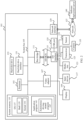
- FIG. 1 is a functional block diagram of a vehicle 100 according to an embodiment of this application.
- the vehicle 100 is configured to be in a fully or partially autonomous driving mode.
- the vehicle 100 in an autonomous driving mode may control the vehicle 100, and may determine current states of the vehicle and an ambient environment of the vehicle through manual operations, determine possible behavior of at least one another vehicle in the ambient environment, determine a confidence level corresponding to a possibility that the another vehicle performs the possible behavior, and control the vehicle 100 based on determined information.
- the vehicle 100 may be set to operate without interaction with a human.
- the vehicle 100 may include various subsystems, for example, a travel system 102, a sensor system 104, a control system 106, one or more peripheral devices 108, a power supply 110, a computer system 112, and a user interface 116.
- the vehicle 100 may include more or fewer subsystems, and each subsystem may include a plurality of elements.
- all the subsystems and elements of the vehicle 100 may be interconnected in a wired or wireless manner.
- the travel system 102 may include a component that provides power for the vehicle 100 to move.
- the travel system 102 may include an engine 118, an energy source 119, a drive apparatus 120, and a wheel/tire 121.
- the engine 118 may be an internal combustion engine, an electric motor, an air compression engine, or a combination of other types of engines, for example, a hybrid engine including a gasoline engine and an electric motor, or a hybrid engine including an internal combustion engine and an air compression engine.
- the engine 118 converts the energy source 119 into mechanical energy.
- Examples of the energy source 119 include gasoline, diesel, other oil-based fuels, propane, other compressed gas-based fuels, ethanol, solar panels, batteries, and other power sources.
- the energy source 119 may also provide energy for another system of the vehicle 100.
- the drive apparatus 120 may transmit mechanical power from the engine 118 to the wheel 121.
- the drive apparatus 120 may include a gearbox, a differential, and a drive shaft.
- the drive apparatus 120 may further include another component, for example, a clutch.
- the drive shaft may include one or more shafts that may be coupled to one or more wheels 121.
- the sensor system 104 may include several sensors that sense information about an environment around the vehicle 100.
- the sensor system 104 may include a positioning system 122 (the positioning system may be a global positioning system (global positioning system, GPS), or may be a Beidou system or another positioning system), an inertial measurement unit (inertial measurement unit, IMU) 124, a radar 126, a laser rangefinder 128, and a camera 130.
- the sensor system 104 may further include sensors (for example, an in-vehicle air quality monitor, a fuel gauge, and an oil temperature gauge) in an internal system of the monitored vehicle 100.
- sensors for example, an in-vehicle air quality monitor, a fuel gauge, and an oil temperature gauge
- One or more pieces of sensor data from these sensors may be used to detect an object and corresponding features (a location, a shape, a direction, a speed, and the like) of the object.
- detection and identification are key functions of a security operation of the autonomous vehicle 100.
- the positioning system 122 may be configured to estimate a geographical location of the vehicle 100.
- the IMU 124 is configured to sense location and orientation changes of the vehicle 100 based on inertial acceleration.
- the IMU 124 may be a combination of an accelerometer and a gyroscope.
- the radar 126 may sense an object in the ambient environment of the vehicle 100 by using a radio signal. In some embodiments, in addition to sensing a target object, the radar 126 may be further configured to sense one or more states of a speed, a location, and a forward direction of the target object.
- the laser rangefinder 128 may sense, by using a laser, an object in an environment in which the vehicle 100 is located.
- the laser rangefinder 128 may include one or more laser sources, a laser scanner, one or more detectors, and another system component.
- the camera 130 may be configured to capture a plurality of images of the ambient environment of the vehicle 100.
- the camera 130 may be a static camera or a video camera.
- the control system 106 controls operations of the vehicle 100 and the components of the vehicle.
- the control system 106 may include various elements, including a steering system 132, a throttle 134, a brake unit 136, a computer vision system 140, a route control system 142, and an obstacle avoidance system 144.
- the steering system 132 may be operated to adjust a forward direction of the vehicle 100.
- the steering system may be a steering wheel system.
- the throttle 134 is configured to control an operating speed of the engine 118 and further control a speed of the vehicle 100.
- the brake unit 136 is configured to control the vehicle 100 to decelerate.
- the brake unit 136 may use friction to reduce a rotational speed of the wheel 121.
- the brake unit 136 may convert kinetic energy of the wheel 121 into a current.
- the brake unit 136 may alternatively use another form to reduce a rotational speed of the wheel 121, to control the speed of the vehicle 100.
- the computer vision system 140 may be operated to process and analyze an image captured by the camera 130, to recognize an object and/or a feature in the ambient environment of the vehicle 100.
- the object and/or the feature may include a traffic signal, a road boundary, and an obstacle.
- the computer vision system 140 may use an object recognition algorithm, a structure from motion (structure from motion, SFM) algorithm, video tracking, and another computer vision technology.
- the computer vision system 140 may be configured to: draw a map for an environment, trail an object, estimate an object speed, and the like.
- the route control system 142 is configured to determine a travel route of the vehicle 100. In some embodiments, the route control system 142 may determine a driving route for the vehicle 100 with reference to data from the sensors, the GPS 122, and one or more predetermined maps.
- the obstacle avoidance system 144 is configured to recognize, evaluate, and avoid or surmount, in other manners, potential obstacles in the environment of the vehicle 100.
- control system 106 may additionally or alternatively include components in addition to those shown and described.
- control system may not include some of the components shown above.
- the vehicle 100 interacts with an external sensor, another vehicle, another computer system, or a user by using the peripheral device 108.
- the peripheral device 108 may include a wireless communications system 146, a vehicle-mounted computer 148, a microphone 150, and/or a speaker 152.
- the peripheral device 108 provides a means for a user of the vehicle 100 to interact with the user interface 116.
- the vehicle-mounted computer 148 may provide information for the user of the vehicle 100.
- the user interface 116 may further operate the vehicle-mounted computer 148 to receive an input of the user.
- the vehicle-mounted computer 148 may be operated by using a touchscreen.
- the peripheral device 108 may provide a means for the vehicle 100 to communicate with another device located in the vehicle.
- the microphone 150 may receive audio (for example, according to a voice command or based on other audio input) from the user of the vehicle 100.
- the speaker 152 may output audio to the user of the vehicle 100.
- the wireless communications system 146 may communicate wirelessly with one or more devices directly or through a communications network.
- the wireless communications system 146 may use 3G cellular communications, for example, code division multiple access (code division multiple access, CDMA), global system for mobile communications (Global System for Mobile Communications, GSM)/GPRS, fourth generation (fourth generation, 4G) communications, for example, LTE, or 5th-generation (5th-Generation, 5G) communications.
- the wireless communications system 146 may communicate with a wireless local area network (wireless local area network, WLAN) by using Wi-Fi.
- the wireless communications system 146 may communicate directly with a device by using an infrared link, Bluetooth, or ZigBee (ZigBee).
- Other wireless protocols for example, various vehicle communications systems such as the wireless communications system 146, may include one or more dedicated short range communications (dedicated short range communications, DSRC) devices, which may include public and/or private data communications between vehicles and/or roadside stations.
- DSRC dedicated short range communications
- the power supply 110 may supply power to various components of the vehicle 100.
- the power supply 110 may be a rechargeable lithium-ion or lead-acid battery.
- One or more battery packs of such batteries may be configured as the power supply to supply power to the components of the vehicle 100.
- the power supply 110 and the energy source 119 may be implemented together, for example, in some pure electric vehicles.
- the computer system 112 may include at least one processor 113.
- the processor 113 executes instructions 115 stored in a non-transitory computer-readable medium such as a data memory 114.
- the computer system 112 may alternatively be a plurality of computing devices that control an individual component or a subsystem of the vehicle 100 in a distributed manner.
- the processor 113 may be any conventional processor, such as a commercially available central processing unit (central processing unit, CPU). Alternatively, the processor may be a dedicated device such as an application-specific integrated circuit (application-specific integrated circuit, ASIC) or another hardware-based processor.
- FIG. 1 functionally illustrates the processor, the memory, and other elements of the computer 110 in a same block, a person of ordinary skill in the art should understand that the processor, the computer, or the memory may actually include a plurality of processors, computers, or memories that may or may not be stored in a same physical housing.
- the memory may be a hard disk drive, or another storage medium not located in a housing of the computer 110.
- a reference to the processor or the computer includes a reference to a set of processors or computers or memories that may or may not operate in parallel.
- some components such as a steering component and a deceleration component may include respective processors.
- the processor performs only computation related to a component-specific function.
- the processor may be located far away from the vehicle and wirelessly communicate with the vehicle.
- some of processes described herein are performed on a processor disposed inside the vehicle, while others are performed by a remote processor.
- the processes include necessary steps for performing a single operation.
- the memory 114 may include the instructions 115 (for example, program logics), and the instructions 115 may be executed by the processor 113 to perform various functions of the vehicle 100, including the functions described above.
- the memory 114 may also include additional instructions, including instructions used to send data to, receive data from, interact with, and/or control one or more of the travel system 102, the sensor system 104, the control system 106, and the peripheral device 108.
- the memory 114 may further store data, such as a road map, route information, a location, a direction, a speed, and other vehicle data of the vehicle, and other information. Such information may be used by the vehicle 100 and the computer system 112 when the vehicle 100 operates in an autonomous mode, a semi-autonomous mode, and/or a manual mode.
- the processor 113 may further execute a solution for planning a vertical motion parameter of the vehicle in this embodiment of this application, to help the vehicle plan the vertical motion parameter.
- a solution for planning a vertical motion parameter of the vehicle in this embodiment of this application to help the vehicle plan the vertical motion parameter.
- the user interface 116 is configured to provide information for or receive information from the user of the vehicle 100.
- the user interface 116 may include one or more input/output devices within a set of peripheral devices 108, such as the wireless communications system 146, the vehicle-mounted computer 148, the microphone 150, and the speaker 152.
- the computer system 112 may control the functions of the vehicle 100 based on inputs received from various subsystems (for example, the travel system 102, the sensor system 104, and the control system 106) and from the user interface 116. For example, the computer system 112 may use input from the control system 106 to control the steering unit 132 to avoid an obstacle detected by the sensor system 104 and the obstacle avoidance system 144. In some embodiments, the computer system 112 may operate to provide control over many aspects of the vehicle 100 and the subsystems of the vehicle 100.
- various subsystems for example, the travel system 102, the sensor system 104, and the control system 106
- the computer system 112 may use input from the control system 106 to control the steering unit 132 to avoid an obstacle detected by the sensor system 104 and the obstacle avoidance system 144.
- the computer system 112 may operate to provide control over many aspects of the vehicle 100 and the subsystems of the vehicle 100.
- one or more of the foregoing components may be installed separately from or associated with the vehicle 100.
- the memory 114 may exist partially or completely separate from the vehicle 100.
- the foregoing components may be communicatively coupled together in a wired and/or wireless manner.
- FIG. 1 should not be construed as a limitation on embodiments of the present invention.
- An autonomous vehicle driving on a road may identify an object in an ambient environment of the vehicle to determine an adjustment to a current speed.
- the object may be another vehicle, a traffic control device, or another type of object.
- the autonomous vehicle may independently consider each identified object, and may determine a to-be-adjusted speed of the autonomous vehicle based on characteristics of each identified object, such as a current speed of the object, acceleration of the object, and a distance between the object and the autonomous vehicle.
- the autonomous vehicle 100 or a computing device associated with the autonomous vehicle 100 may predict behavior of the identified object based on a feature of the identified object and a state of the ambient environment (for example, traffic, rain, and ice on a road).
- identified objects depend on behavior of each other, and therefore all the identified objects may be considered together to predict behavior of a single identified object.
- the vehicle 100 can adjust the speed of the vehicle based on the predicted behavior of the identified object.
- the automatic driving car can determine, based on the predicted behavior of the object, a stable state to which the vehicle needs to be adjusted (for example, acceleration, deceleration, or stop).
- another factor may also be considered to determine the speed of the vehicle 100, for example, a horizontal location of the vehicle 100 on a road on which the vehicle travels, a curvature of the road, and proximity between a static object and a dynamic object.
- the computing device may provide an instruction for modifying a steering angle of the vehicle 100, so that the autonomous vehicle follows a given trajectory and/or maintains safe transverse and longitudinal distances from an object (for example, a car in an adjacent lane on the road) next to the autonomous vehicle.
- an object for example, a car in an adjacent lane on the road
- the vehicle 100 may be a car, a truck, a motorcycle, a bus, a boat, an airplane, a helicopter, a lawn mower, a recreational vehicle, a playground vehicle, a construction device, a trolley, a golf cart, a train, a handcart, or the like. This is not specifically limited in embodiments of the present invention.
- FIG. 2 is a schematic diagram of an autonomous driving system to which an embodiment of this application is applicable.
- a computer system 101 includes a processor 103, and the processor 103 is coupled to a system bus 105.
- the processor 103 may be one or more processors, and each processor may include one or more processor cores.
- a video adapter (video adapter) 107 where the video adapter may drive a display 109, and the display 109 is coupled to the system bus 105.
- the system bus 105 is coupled to an input/output (input/output, I/O) bus 113 through a bus bridge 111.
- An I/O interface 115 is coupled to the I/O bus.
- the I/O interface 115 communicates with a plurality of I/O devices, for example, an input device 117 (such as a keyboard, a mouse, and a touchscreen) and a media tray (media tray) 121 (such as a CD-ROM and a multimedia interface).
- a transceiver 123 which may send and/or receive a radio communications signal
- a camera 155 which may capture static and dynamic digital video images
- an external USB interface 125 are provided.
- an interface connected to the I/O interface 115 may be a USB port.
- the processor 103 may be any conventional processor, including a reduced instruction set computing (Reduced Instruction Set Computing, RISC) processor, a complex instruction set computing (Complex Instruction Set Computing, CISC) processor, or a combination thereof.
- the processor may be a dedicated apparatus such as an application-specific integrated circuit (ASIC).
- the processor 103 may be a neural network processor or a combination of the neural network processor and the foregoing conventional processor.
- the computer system 101 may be located away from an autonomous vehicle, and may wirelessly communicate with the autonomous vehicle.
- some of processes described herein are performed on a processor disposed in the autonomous vehicle, and others are performed by a remote processor, including taking an action required to perform a single manipulation.
- the computer 101 may communicate with a software deploying server 149 by using a network interface 129.
- the network interface 129 is a hardware network interface, such as a network adapter.
- a network 127 may be an external network such as the Internet, or an internal network such as the Ethernet or a virtual private network (virtual private network, VPN).
- the network 127 may alternatively be a wireless network, for example, a Wi-Fi network or a cellular network.
- a hard disk drive interface is coupled to the system bus 105.
- the hardware drive interface is connected to a hard disk drive.
- a system memory 135 is coupled to the system bus 105. Data running in the system memory 135 may include an operating system 137 and an application program 143 of the computer 101.
- the operating system includes a shell (shell) 139 and a kernel (kernel) 141.
- the shell 139 is an interface between a user and the kernel of the operating system.
- the shell 139 is an outermost layer of the operating system.
- the shell 139 manages interaction between the user and the operating system: waiting for input of the user, explaining the input of the user to the operating system, and processing various output results of the operating system.
- the kernel 141 includes parts of the operating system that are used for managing a memory, a file, a peripheral device, and a system resource.
- the kernel of the operating system When directly interacting with hardware, the kernel of the operating system usually runs a process, provides inter-process communication, and provides functions such as CPU time slice management, interrupt, memory management, and I/O management.
- the application program 143 includes a program related to controlling autonomous driving of the vehicle, for example, a program for managing interaction between the autonomous vehicle and a road obstacle, a program for controlling a route or a speed of the autonomous vehicle, and a program for controlling interaction between the autonomous vehicle and another autonomous vehicle on the road.
- the application program 143 may be on a system of the software deploying server (deploying server) 149.
- the computer system 101 may download the application program 143 from the software deploying server (deploying server) 149.
- the application program may further include an application program corresponding to a solution of target object perception provided in embodiments of this application.
- the solution of target object perception in embodiments of this application is specifically described below. For brevity, details are not described herein again.
- a sensor 153 is associated with the computer system 101.
- the sensor 153 is configured to detect an ambient environment of the computer 101.
- the sensor 153 may detect a target object, for example, an animal, a vehicle, or an obstacle.
- the sensor may detect an ambient environment of the target object, for example, an environment around the animal, another animal appearing around the animal, a weather condition, or brightness of the ambient environment.
- the sensor may be a laser radar, a camera, an infrared sensor, a chemical detector, a microphone, or the like.
- FIG. 3 is a schematic diagram of a system 300 that includes an autonomous vehicle and a cloud service center and to which an embodiment of this application is applicable.
- the cloud service center 310 may receive information from an autonomous vehicle 330 and an autonomous vehicle 331 via a network 320, such as a wireless communications network.
- the received information may be a location of a target object, a speed of the target object, or the like sent by the autonomous vehicle 330 and/or the autonomous vehicle 331.
- the target object may be a traffic element detected by a vehicle that collects data in a running process, for example, another vehicle, a pedestrian, or a traffic signal light.
- the cloud service center 310 runs, based on received data, a program that is stored in the cloud service center and that is related to controlling autonomous driving of a vehicle, to control the autonomous vehicles 330 and 331.
- the program related to controlling autonomous driving of a vehicle may include a program related to controlling autonomous driving of the vehicle, a program for managing interaction between the autonomous vehicle and a road obstacle, a program for controlling a route or a speed of the autonomous vehicle, and a program for controlling interaction between the autonomous vehicle and another autonomous vehicle on the road.
- the network 320 provides a portion of a map outward to the autonomous vehicle 330 or 331.
- operations may be divided between different locations.
- a plurality of cloud service centers may receive, acknowledge, combine, and/or send information reports.
- information reports and/or sensor data may also be sent between autonomous vehicles. Another configuration is also possible.
- the center sends a suggested solution to the autonomous vehicle for possible driving conditions within the system 300 (For example, informing a forward obstacle and telling how to bypass the forward obstacle).
- the cloud service center may assist the vehicle in determining how to travel when there is a specific obstacle ahead in the environment.
- the cloud service center sends, to the autonomous vehicle, a response indicating how the vehicle should travel in a given scenario.
- the cloud service center may determine, based on collected sensor data, that there is a temporary stop sign in the road ahead, and further determine, based on a "lane closed" sign and sensor data from a construction vehicle, that the lane is closed due to construction.
- the cloud server center sends a suggested operation mode used by the autonomous vehicle to go around the obstacle (for example, indicating the vehicle to change the lane to another road).
- a suggested operation mode used by the autonomous vehicle for example, indicating the vehicle to change the lane to another road.
- operation steps used for the autonomous vehicle may be added to a driving information map.
- the information may be sent to another vehicle that may encounter a same obstacle in the region, to assist the another vehicle not only in recognizing the closed lane but also in knowing how to go around.
- a solution in which a plurality of vehicles cooperatively collect observation data of a traffic element in a traffic scenario is usually used to improve accuracy of obtained observation data of the traffic element in the traffic scenario.
- the plurality of vehicles cooperatively collect the observation data there is an error in observation data collected by the vehicles in terms of time and space. Consequently, in a process of integrating data, observation data of a same traffic element may be identified as observation data of different traffic elements, or observation data of different traffic elements is identified as observation data of a same traffic element. As a result, an observation result of the traffic element is inaccurate.
- this application provides a new traffic element observation solution.
- observation data that is of a traffic element and that is collected by a plurality of vehicles is synchronized in terms of time, and/or corrected in terms of space, and the observation data collected by the plurality of vehicles is adjusted and then integrated, to obtain a final observation result of the traffic element, so as to improve accuracy of the observation result of the traffic element.
- the following describes a traffic element observation method according to an embodiment of this application with reference to FIG. 4 .
- FIG. 4 is a flowchart of a traffic element observation method according to an embodiment of this application.
- the method shown in FIG. 4 may be performed by the cloud service center 310 shown in FIG. 3 , or may be performed by another computing device. This is not limited in this embodiment of this application.
- the method shown in FIG. 4 includes steps 410 to 430.
- the traffic element may include a dynamic obstacle or a static obstacle in a traffic scenario.
- the dynamic obstacle may be a vehicle other than the vehicle that collects the first observation data, or may be a pedestrian or the like in the traffic scenario.
- the static obstacle may be a traffic signal light or the like.
- the first observation data may include at least one of a type of the target object, a motion status of the target object, a motion trail of the target object, and a size of the target object.
- the type of the target object may include a vehicle, a pedestrian, a bicycle, and the like.
- the motion status of the target object may include a static state and a dynamic state.
- the motion trail of the target object may include a speed trail of the target object and a spatial trail of the target object.
- the size of the target object may include a length of the target object and a width of the target object.
- the first observation data further includes time serving information of the traffic signal light.
- the plurality of groups of first observation data are obtained after being collected by an in-vehicle sensor in each of the plurality of vehicles and processed by a multi-domain controller (multi-domain controller, MDC).
- MDC multi-domain controller
- a vehicle observation accuracy is high, and may be about 3 cm to 4 cm.
- a distance between a vehicle #1 and the traffic element is 200 meters, and a distance between a vehicle #2 and the traffic element is 100 meters.
- accuracy of observation data based on the distance from the vehicle #1 to the traffic element may be low.
- the accuracy of observation data that is of the traffic element and that is collected by the vehicle #1 can be compensated by using observation data that is of the traffic element and that is collected by the vehicle # 2.
- a distance between every two of the plurality of vehicles is not specifically limited in this embodiment of this application.
- the plurality of vehicles are intelligent vehicles.
- the foregoing time synchronization processing and space correction processing may be selected based on a type of the observation data. If the observation data includes location information of the traffic element, space correction processing may be performed on observation data of this type. For example, when the observation data includes a coordinate location of the traffic element, space correction processing and time synchronization processing may be performed on observation data of this type. If the observation data includes time information, time synchronization can be performed on observation data of this type. For example, if the observation data includes a speed curve of the traffic element, time synchronization processing may be performed on observation data of this type.
- the foregoing step 420 includes: determining a time offset between the plurality of groups of first observation data; and adjusting each of the plurality of groups of first observation data based on the time offset between the plurality of groups of first observation data, to obtain the plurality of groups of processed observation data, where time points of all of the plurality of groups of processed observation data are synchronized.
- the time offset between the plurality of groups of first observation data may be an average value of time offsets between every two of the plurality of groups of first observation data, or may be a minimum value in time offsets between every two of the plurality of groups of first observation data, or may be a maximum value in time offsets between every two of the plurality of groups of first observation data. This is not specifically limited in this embodiment of this application.
- the time offset may alternatively be determined based on an offset between longitudes, latitudes or course angles that are of the traffic element and that are collected by all of the vehicles.
- the following describes a method for determining a time offset between the plurality of groups of first observation data by using an example in which an offset between longitudes, latitudes or course angles that are of the traffic element and that are collected by all of the vehicles is calculated by using the least square method.
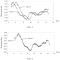
- FIG. 5 is a simulation diagram of observation data collected before time synchronization processing.
- a curve 1 indicates a change of observation data that is of a traffic element 1 and that is collected by the vehicle #1 with time
- a curve 2 indicates a change of observation data that is of the traffic element 1 and that is collected by the vehicle #2 with time. It can be learned that before time synchronization processing, the two curves correspond to different observation data at a same moment.
- FIG. 6 is a simulation diagram of observation data collected after time synchronization processing. It can be learned that after the time synchronization processing method in this embodiment of this application is used, the curve 1 and the curve 2 basically overlap.
- step 420 includes: determining, in a preset coordinate system, coordinates over time that are of the traffic element and that are indicated by each of the plurality of groups of first observation data; and representing a coordinate value that is of the traffic element and that is included in each preset coordinate range in the coordinate system as a target coordinate value corresponding to the coordinate range, to obtain coordinates that are of the traffic element and that are in each preset coordinate range in the coordinate system, where the processed observation data includes the coordinates that are of the traffic element and that are in each preset coordinate range in the coordinate system.
- coordinates that are of the traffic element and that are indicated by each of the plurality of groups of first observation data is located in a grid #1 in the preset coordinate system, and target coordinate values corresponding to the grid #1 is ( x , y ).
- it may be determined that coordinates that are of the traffic element and that are indicated by each group of first observation data at the q th moment is the target coordinate values ( x , y ) corresponding to the grid #1.
- grids in the coordinate system may be divided in advance. This is not limited in this embodiment of this application.
- the change of a coordinate location of the traffic element with time may be determined based on current states (including a location and a speed of the traffic element) that are of the traffic element and that are collected by the plurality of vehicles, and a Kalman filtering algorithm.
- the foregoing Kalman filtering algorithm may be divided into two phases: a prediction phase and an update phase.
- the prediction phase is used to predict a state of a traffic element at a k th moment based on a state of a traffic element at a ( k - 1) th moment.
- the update phase is used to update a variable in the Kalman filtering algorithm based on a predicted state of the traffic element at the k th moment.
- k -1 of the traffic element at the k th moment is predicted by using the formulas x ⁇ k
- k -1 F k x ⁇ k -1
- k ⁇ 1 F k P k ⁇ 1
- control vector and the control matrix may reflect impact of an external factor on the state of the traffic element at the k th moment
- the second covariance matrix may reflect impact of an external uncertainty on the state of the traffic element at the k th moment.
- k -1 , S k H k P k
- k ⁇ 1 H k T ⁇ R k , and K k P k
- the third covariance matrix R k may be set based on noise of the sensor.
- the residual covariance matrix S k and the Kalman gain K k are measured based on the measurement residual vector ⁇ k , and the state x ⁇ k
- k x ⁇ k
- k ( I - K k H k ) P k
- the second observation data may be used as final observation data of the traffic element.
- the plurality of vehicles may further report one or more types of information such as a location of a current vehicle, a speed of the current vehicle, and a state of the current vehicle, so that a cloud computing server determines information such as a relative location and a relative speed between the current vehicle and the traffic element based on the second observation data and the information about the vehicle, and feeds back calculated information to the current vehicle.
- the current vehicle may adjust a driving route, a driving speed, or the like based on the information such as the location of the current vehicle, the speed of the current vehicle, and the state of the current vehicle.
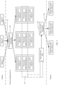
- FIG. 7 is a flowchart of a traffic element observation method according to an embodiment of this application. The method shown in FIG. 7 includes steps 710 to 750.
- the vehicle #1, the vehicle #2, and the vehicle #3 respectively send data collected by the vehicle #1, the vehicle #2, and the vehicle #3 to a cloud server.
- the data uploaded by each of the vehicle includes observation data collected by the vehicle, a traveling trail of the vehicle, and information of the vehicle.
- Observation data #1 is collected by the vehicle #1 and includes data of a traffic element #1
- observation data #2 is collected by the vehicle #2 and includes data of the traffic element #1
- observation data #3 is collected by the vehicle #3 and includes data of the traffic element #1.
- a distance between every two of the vehicle #1, the vehicle #2, and the vehicle #3 is less than or equal to 100 m, and a distance between any one of the vehicles and the traffic element #1 is less than or equal to 100 m, accuracy of data of the traffic element #1 separately collected by the vehicle #1, the vehicle #2, and the vehicle #3 is high.
- the vehicle #1, the vehicle #2, and the vehicle #3 are intelligent vehicles.
- the cloud computing server performs time synchronization processing on the observation data in the foregoing data, to obtain processed observation data #1, processed observation data #2, and processed observation data #3.
- An observation result #1 of the vehicle #1 for the traffic element #1 includes information such as a relative location and a relative speed between the vehicle #1 and the traffic element #1.
- An observation result #2 of the vehicle #2 for the traffic element #1 includes information such as a relative location and a relative speed between the vehicle #2 and the traffic element #1.
- An observation result #3 of the vehicle #3 for the traffic element #1 includes information such as a relative location and a relative speed between the vehicle #3 and the traffic element #1.
- FIG. 8 is a schematic diagram of a traffic element observation apparatus according to an embodiment of this application.
- An apparatus 800 shown in FIG. 8 includes a receiving unit 810 and a processing unit 820.
- the receiving unit 810 is configured to receive a plurality of groups of first observation data that are of a traffic element and that are sent by a plurality of vehicles, where each of the plurality of vehicles collects one of the plurality of groups of first observation data, and the first observation data indicates a change of a coordinate location of the traffic element with time and/or a change of a speed of the traffic element with time.
- the processing unit 820 is configured to perform time synchronization processing and/or space correction processing on the plurality of groups of first observation data, to obtain a plurality of groups of processed observation data.
- the processing unit 820 is further configured to determine, based on the plurality of groups of processed observation data, second observation data that is of the traffic element and that is observed by the plurality of vehicles.
- the processing unit 820 is further configured to: determine a time offset between the plurality of groups of first observation data; and adjust each of the plurality of groups of first observation data based on the time offset between the plurality of groups of first observation data, to obtain the processed observation data, where time points of all groups of the processed observation data are synchronized.
- the processing unit 820 is further configured to: determine, in a preset coordinate system, coordinates that are of the traffic element at different time points and that are indicated by each of the plurality of groups of first observation data; and represent a coordinate value that is of the traffic element and that is included in each preset coordinate range in the coordinate system as a target coordinate value corresponding to the coordinate range, to obtain coordinates that are of the traffic element and that are in each preset coordinate range in the coordinate system, where the processed observation data includes the coordinates that are of the traffic element and that are in each preset coordinate range in the coordinate system.
- the first observation data includes at least one of a type of the target object, a motion status of the target object, a motion trail of the target object, and a size of the target object.
- the first observation data when the target object is a traffic signal light, the first observation data further includes time serving information of the traffic signal light.
- the plurality of groups of first observation data are obtained after being collected by an in-vehicle sensor in each of the plurality of vehicles and processed by a multi-domain controller.
- the receiving unit 810 may be a communications interface 930
- the processing unit 820 may be a processor 920
- the computing device may further include a memory 910. Details are shown in FIG. 9 .
- FIG. 9 is a schematic block diagram of a computing device according to another embodiment of this application.
- the computing device 900 shown in FIG. 9 may include a memory 910, a processor 920, and a communications interface 930.
- the memory 910, the processor 920, and the communications interface 930 are connected by using an internal connection path.
- the memory 910 is configured to store instructions.
- the processor 920 is configured to execute the instructions stored in the memory 920, to control the input/output interface 930 to receive/send at least some parameters of a second channel model.
- the memory 910 may be coupled to the processor 920 through an interface, or may be integrated together with the processor 920.
- the communications interface 930 uses a transceiver apparatus such as but not limited to a transceiver to implement communication between the communications device 900 and another device or a communications network.
- the communications interface 930 may further include an input/output interface (input/output interface).
- steps in the foregoing methods can be implemented by using a hardware integrated logical circuit in the processor 920, or by using instructions in a form of software.
- the methods disclosed with reference to embodiments of this application may be directly performed and completed by using a hardware processor, or may be performed and completed by using a combination of hardware in the processor and a software module.
- the software module may be located in a mature storage medium in the art, such as a random access memory, a flash memory, a read-only memory, a programmable read-only memory, an electrically erasable programmable memory, a register, or the like.
- the storage medium is located in the memory 910, and the processor 920 reads information in the memory 910 and completes the steps in the foregoing methods in combination with the hardware of the processor. To avoid repetition, details are not described herein again.
- the processor in embodiments of this application may be a central processing unit (central processing unit, CPU), or may further be another general-purpose processor, a digital signal processor (digital signal processor, DSP), an application-specific integrated circuit (application-specific integrated circuit, ASIC), a field programmable gate array (field programmable gate array, FPGA), or another programmable logic device, discrete gate or transistor logic device, discrete hardware component, or the like.
- the general-purpose processor may be a microprocessor, or the processor may further be any conventional processor, or the like.
- the memory may include a read-only memory and a random access memory, and provide instructions and data for the processor.
- a part of the processor may further include a non-volatile random access memory.
- the processor may further store information about a device type.
- sequence numbers of the foregoing processes do not mean execution sequences in various embodiments of this application.
- the execution sequences of the processes should be determined according to functions and internal logic of the processes, and should not be construed as any limitation on the implementation processes of embodiments of this application.
- the disclosed systems, apparatuses, and methods may be implemented in other manners.
- the described apparatus embodiments are merely examples.
- division into the units is merely logical function division and may be other division during an actual implementation.
- a plurality of units or components may be combined or integrated into another system, or some features may be ignored or may not be performed.
- the displayed or discussed mutual couplings or direct couplings or communication connections may be implemented by using some interfaces. Indirect couplings or communication connections between the apparatuses or units may be implemented in an electrical form, a mechanical form, or another form.
- the units described as separate parts may or may not be physically separate, and parts displayed as units may or may not be physical units, may be located in one position, or may be distributed on a plurality of network units. Some or all of the units may be selected based on actual requirements to achieve the objectives of the solutions of embodiments.
- the functions When the functions are implemented in a form of a software functional unit and sold or used as an independent product, the functions may be stored in a computer-readable storage medium. Based on such an understanding, the technical solutions of this application essentially, or the part contributing to the conventional technology, or some of the technical solutions may be implemented in a form of a software product.
- the computer software product is stored in a storage medium, and includes several instructions for instructing a computer device (which may be a personal computer, a server, or a network device) to perform all or some of the steps of the methods described in embodiments of this application.
- the foregoing storage medium includes: any medium that can store program code, such as a USB flash disk, a removable hard disk, a read-only memory (read-only memory, ROM), a random access memory (random access memory, RAM), a magnetic disk, or an optical disc.
- program code such as a USB flash disk, a removable hard disk, a read-only memory (read-only memory, ROM), a random access memory (random access memory, RAM), a magnetic disk, or an optical disc.
Landscapes
- Physics & Mathematics (AREA)
- General Physics & Mathematics (AREA)
- Chemical & Material Sciences (AREA)
- Analytical Chemistry (AREA)
- Life Sciences & Earth Sciences (AREA)
- Atmospheric Sciences (AREA)
- Traffic Control Systems (AREA)
Applications Claiming Priority (1)
| Application Number | Priority Date | Filing Date | Title |
|---|---|---|---|
| PCT/CN2020/117785 WO2022061725A1 (fr) | 2020-09-25 | 2020-09-25 | Procédé et appareil d'observation d'élément de circulation |
Publications (2)
| Publication Number | Publication Date |
|---|---|
| EP4207133A1 true EP4207133A1 (fr) | 2023-07-05 |
| EP4207133A4 EP4207133A4 (fr) | 2023-11-01 |
Family
ID=75291151
Family Applications (1)
| Application Number | Title | Priority Date | Filing Date |
|---|---|---|---|
| EP20954577.1A Pending EP4207133A4 (fr) | 2020-09-25 | 2020-09-25 | Procédé et appareil d'observation d'élément de circulation |
Country Status (3)
| Country | Link |
|---|---|
| EP (1) | EP4207133A4 (fr) |
| CN (1) | CN112639910B (fr) |
| WO (1) | WO2022061725A1 (fr) |
Family Cites Families (21)
| Publication number | Priority date | Publication date | Assignee | Title |
|---|---|---|---|---|
| JP2002157696A (ja) * | 2000-11-22 | 2002-05-31 | Natl Inst For Land & Infrastructure Management Mlit | 専用レーンを有するahsにおける障害物回避方法 |
| JP4271720B1 (ja) * | 2008-04-24 | 2009-06-03 | 本田技研工業株式会社 | 車両周辺監視装置 |
| US20140078304A1 (en) * | 2012-09-20 | 2014-03-20 | Cloudcar, Inc. | Collection and use of captured vehicle data |
| CN104217615B (zh) * | 2014-09-16 | 2016-08-24 | 武汉理工大学 | 一种基于车路协同的行人防碰撞系统和方法 |
| CN105741546B (zh) * | 2016-03-18 | 2018-06-29 | 重庆邮电大学 | 路侧设备与车传感器融合的智能车辆目标跟踪系统及方法 |
| US11436539B2 (en) * | 2017-05-26 | 2022-09-06 | Google Llc | Vehicle map service system |
| CN109872530B (zh) * | 2017-12-05 | 2022-02-15 | 广州腾讯科技有限公司 | 一种路况信息的生成方法、车载终端及服务器 |
| CN109900490B (zh) * | 2017-12-11 | 2020-11-03 | 上海交通大学 | 基于自主式和协同式传感器的车辆运动状态检测方法及系统 |
| DE102018216809A1 (de) * | 2018-09-28 | 2020-04-02 | Robert Bosch Gmbh | Verfahren, Vorrichtung und Sensorsystem zur Umfelderfassung für ein Fahrzeug |
| CN109556615B (zh) * | 2018-10-10 | 2022-10-04 | 吉林大学 | 基于自动驾驶的多传感器融合认知的驾驶地图生成方法 |
| CN111243281A (zh) * | 2018-11-09 | 2020-06-05 | 杭州海康威视系统技术有限公司 | 一种道路多视频联合检测系统及检测方法 |
| CN111402574B (zh) * | 2018-12-13 | 2023-04-07 | 阿里巴巴集团控股有限公司 | 车辆检测方法、装置、设备和存储介质 |
| US11436923B2 (en) * | 2019-01-25 | 2022-09-06 | Cavh Llc | Proactive sensing systems and methods for intelligent road infrastructure systems |
| CN110208158A (zh) * | 2019-06-13 | 2019-09-06 | 上汽大众汽车有限公司 | 一种车辆环境检测传感器在线校准方法及系统 |
| CN111193568A (zh) * | 2019-12-19 | 2020-05-22 | 北汽福田汽车股份有限公司 | 时间同步方法、装置、系统、存储介质及车辆 |
| CN111209956A (zh) * | 2020-01-02 | 2020-05-29 | 北京汽车集团有限公司 | 传感器数据融合方法、车辆的环境地图生成方法及系统 |
| CN111222568B (zh) * | 2020-01-03 | 2024-06-11 | 北京汽车集团有限公司 | 一种车辆网联数据融合方法及装置 |
| CN111383287B (zh) * | 2020-02-13 | 2021-06-29 | 湖北亿咖通科技有限公司 | 一种车载传感器的外参标定方法及装置 |
| CN111220998B (zh) * | 2020-02-26 | 2022-10-28 | 江苏大学 | 一种基于车车通信的多目标协同跟踪的方法 |
| CN111459168B (zh) * | 2020-04-23 | 2021-12-10 | 上海交通大学 | 一种融合的自动驾驶汽车过街行人轨迹预测方法及系统 |
| CN111596090A (zh) * | 2020-06-17 | 2020-08-28 | 中国第一汽车股份有限公司 | 车辆行驶速度的测量方法、装置、车辆和介质 |
-
2020
- 2020-09-25 EP EP20954577.1A patent/EP4207133A4/fr active Pending
- 2020-09-25 CN CN202080004590.9A patent/CN112639910B/zh active Active
- 2020-09-25 WO PCT/CN2020/117785 patent/WO2022061725A1/fr not_active Ceased
Also Published As
| Publication number | Publication date |
|---|---|
| CN112639910B (zh) | 2022-05-17 |
| WO2022061725A1 (fr) | 2022-03-31 |
| CN112639910A (zh) | 2021-04-09 |
| EP4207133A4 (fr) | 2023-11-01 |
Similar Documents
| Publication | Publication Date | Title |
|---|---|---|
| US20220332348A1 (en) | Autonomous driving method, related device, and computer-readable storage medium | |
| US12061088B2 (en) | Obstacle avoidance method and apparatus | |
| US12001517B2 (en) | Positioning method and apparatus | |
| CN113498529B (zh) | 一种目标跟踪方法及其装置 | |
| EP4141736A1 (fr) | Procédé et appareil de suivi de voie | |
| US12409849B2 (en) | Method and apparatus for passing through barrier gate crossbar by vehicle | |
| WO2021102955A1 (fr) | Procédé et appareil de planification de trajet pour véhicule | |
| EP4280129A1 (fr) | Procédé et appareil de prédiction de trajectoire, et carte | |
| US20230227052A1 (en) | Fault diagnosis method and fault diagnosis device for vehicle speed measurement device | |
| EP4167126A1 (fr) | Procédé d'inférence de voie et procédé et appareil d'entraînement de modèle d'inférence de voie | |
| CN115039095B (zh) | 目标跟踪方法以及目标跟踪装置 | |
| US12358508B2 (en) | Lane change track planning method and apparatus | |
| WO2021159397A1 (fr) | Procédé de détection et dispositif de détection de région pouvant être parcourue par un véhicule | |
| EP4307251A1 (fr) | Procédé de mappage, véhicule, support d'informations lisible par ordinateur, et puce | |
| CN114092898A (zh) | 目标物的感知方法及装置 | |
| EP4664159A1 (fr) | Procédé de traitement de données, support de stockage lisible et dispositif électronique | |
| CN112810603B (zh) | 定位方法和相关产品 | |
| EP4159564B1 (fr) | Procédé et dispositif de planification de paramètres de mouvement longitudinal de véhicule | |
| US12394218B2 (en) | Method and apparatus for generating lane line, vehicle, storage medium and chip | |
| CN112639910B (zh) | 交通元素的观测方法和装置 | |
| CN114556251B (zh) | 用于确定车辆可通行空间的方法和装置 |
Legal Events
| Date | Code | Title | Description |
|---|---|---|---|
| STAA | Information on the status of an ep patent application or granted ep patent |
Free format text: STATUS: THE INTERNATIONAL PUBLICATION HAS BEEN MADE |
|
| PUAI | Public reference made under article 153(3) epc to a published international application that has entered the european phase |
Free format text: ORIGINAL CODE: 0009012 |
|
| STAA | Information on the status of an ep patent application or granted ep patent |
Free format text: STATUS: REQUEST FOR EXAMINATION WAS MADE |
|
| 17P | Request for examination filed |
Effective date: 20230330 |
|
| AK | Designated contracting states |
Kind code of ref document: A1 Designated state(s): AL AT BE BG CH CY CZ DE DK EE ES FI FR GB GR HR HU IE IS IT LI LT LU LV MC MK MT NL NO PL PT RO RS SE SI SK SM TR |
|
| A4 | Supplementary search report drawn up and despatched |
Effective date: 20230929 |
|
| RIC1 | Information provided on ipc code assigned before grant |
Ipc: G08G 1/16 20060101ALI20230925BHEP Ipc: G08G 1/0962 20060101ALI20230925BHEP Ipc: G08G 1/01 20060101ALI20230925BHEP Ipc: G08G 1/0967 20060101AFI20230925BHEP |
|
| DAV | Request for validation of the european patent (deleted) | ||
| DAX | Request for extension of the european patent (deleted) | ||
| RAP1 | Party data changed (applicant data changed or rights of an application transferred) |
Owner name: SHENZHEN YINWANG INTELLIGENTTECHNOLOGIES CO., LTD. |
|
| STAA | Information on the status of an ep patent application or granted ep patent |
Free format text: STATUS: EXAMINATION IS IN PROGRESS |
|
| 17Q | First examination report despatched |
Effective date: 20251201 |