EP4207144B1 - Dispositif d'affichage flexible pliable et dispositif électronique - Google Patents
Dispositif d'affichage flexible pliable et dispositif électronique Download PDFInfo
- Publication number
- EP4207144B1 EP4207144B1 EP21919873.6A EP21919873A EP4207144B1 EP 4207144 B1 EP4207144 B1 EP 4207144B1 EP 21919873 A EP21919873 A EP 21919873A EP 4207144 B1 EP4207144 B1 EP 4207144B1
- Authority
- EP
- European Patent Office
- Prior art keywords
- cam
- sliding cam
- housing
- sliding
- rotation
- Prior art date
- Legal status (The legal status is an assumption and is not a legal conclusion. Google has not performed a legal analysis and makes no representation as to the accuracy of the status listed.)
- Active
Links
Images







Classifications
-
- G—PHYSICS
- G09—EDUCATION; CRYPTOGRAPHY; DISPLAY; ADVERTISING; SEALS
- G09F—DISPLAYING; ADVERTISING; SIGNS; LABELS OR NAME-PLATES; SEALS
- G09F9/00—Indicating arrangements for variable information in which the information is built-up on a support by selection or combination of individual elements
- G09F9/30—Indicating arrangements for variable information in which the information is built-up on a support by selection or combination of individual elements in which the desired character or characters are formed by combining individual elements
- G09F9/301—Indicating arrangements for variable information in which the information is built-up on a support by selection or combination of individual elements in which the desired character or characters are formed by combining individual elements flexible foldable or roll-able electronic displays, e.g. thin LCD, OLED
-
- G—PHYSICS
- G06—COMPUTING OR CALCULATING; COUNTING
- G06F—ELECTRIC DIGITAL DATA PROCESSING
- G06F1/00—Details not covered by groups G06F3/00 - G06F13/00 and G06F21/00
- G06F1/16—Constructional details or arrangements
- G06F1/1613—Constructional details or arrangements for portable computers
- G06F1/1633—Constructional details or arrangements of portable computers not specific to the type of enclosures covered by groups G06F1/1615 - G06F1/1626
- G06F1/1675—Miscellaneous details related to the relative movement between the different enclosures or enclosure parts
- G06F1/1681—Details related solely to hinges
-
- G—PHYSICS
- G06—COMPUTING OR CALCULATING; COUNTING
- G06F—ELECTRIC DIGITAL DATA PROCESSING
- G06F1/00—Details not covered by groups G06F3/00 - G06F13/00 and G06F21/00
- G06F1/16—Constructional details or arrangements
- G06F1/1613—Constructional details or arrangements for portable computers
- G06F1/1615—Constructional details or arrangements for portable computers with several enclosures having relative motions, each enclosure supporting at least one I/O or computing function
- G06F1/1616—Constructional details or arrangements for portable computers with several enclosures having relative motions, each enclosure supporting at least one I/O or computing function with folding flat displays, e.g. laptop computers or notebooks having a clamshell configuration, with body parts pivoting to an open position around an axis parallel to the plane they define in closed position
-
- G—PHYSICS
- G06—COMPUTING OR CALCULATING; COUNTING
- G06F—ELECTRIC DIGITAL DATA PROCESSING
- G06F1/00—Details not covered by groups G06F3/00 - G06F13/00 and G06F21/00
- G06F1/16—Constructional details or arrangements
- G06F1/1613—Constructional details or arrangements for portable computers
- G06F1/1615—Constructional details or arrangements for portable computers with several enclosures having relative motions, each enclosure supporting at least one I/O or computing function
- G06F1/1624—Constructional details or arrangements for portable computers with several enclosures having relative motions, each enclosure supporting at least one I/O or computing function with sliding enclosures, e.g. sliding keyboard or display
-
- G—PHYSICS
- G06—COMPUTING OR CALCULATING; COUNTING
- G06F—ELECTRIC DIGITAL DATA PROCESSING
- G06F1/00—Details not covered by groups G06F3/00 - G06F13/00 and G06F21/00
- G06F1/16—Constructional details or arrangements
- G06F1/1613—Constructional details or arrangements for portable computers
- G06F1/1633—Constructional details or arrangements of portable computers not specific to the type of enclosures covered by groups G06F1/1615 - G06F1/1626
- G06F1/1637—Details related to the display arrangement, including those related to the mounting of the display in the housing
- G06F1/1652—Details related to the display arrangement, including those related to the mounting of the display in the housing the display being flexible, e.g. mimicking a sheet of paper, or rollable
-
- G—PHYSICS
- G06—COMPUTING OR CALCULATING; COUNTING
- G06F—ELECTRIC DIGITAL DATA PROCESSING
- G06F1/00—Details not covered by groups G06F3/00 - G06F13/00 and G06F21/00
- G06F1/16—Constructional details or arrangements
- G06F1/1613—Constructional details or arrangements for portable computers
- G06F1/1633—Constructional details or arrangements of portable computers not specific to the type of enclosures covered by groups G06F1/1615 - G06F1/1626
- G06F1/1675—Miscellaneous details related to the relative movement between the different enclosures or enclosure parts
- G06F1/1679—Miscellaneous details related to the relative movement between the different enclosures or enclosure parts for locking or maintaining the movable parts of the enclosure in a fixed position, e.g. latching mechanism at the edge of the display in a laptop or for the screen protective cover of a PDA
-
- G—PHYSICS
- G09—EDUCATION; CRYPTOGRAPHY; DISPLAY; ADVERTISING; SEALS
- G09F—DISPLAYING; ADVERTISING; SIGNS; LABELS OR NAME-PLATES; SEALS
- G09F9/00—Indicating arrangements for variable information in which the information is built-up on a support by selection or combination of individual elements
- G09F9/30—Indicating arrangements for variable information in which the information is built-up on a support by selection or combination of individual elements in which the desired character or characters are formed by combining individual elements
-
- H—ELECTRICITY
- H04—ELECTRIC COMMUNICATION TECHNIQUE
- H04M—TELEPHONIC COMMUNICATION
- H04M1/00—Substation equipment, e.g. for use by subscribers
- H04M1/02—Constructional features of telephone sets
-
- H—ELECTRICITY
- H04—ELECTRIC COMMUNICATION TECHNIQUE
- H04M—TELEPHONIC COMMUNICATION
- H04M1/00—Substation equipment, e.g. for use by subscribers
- H04M1/02—Constructional features of telephone sets
- H04M1/0202—Portable telephone sets, e.g. cordless phones, mobile phones or bar type handsets
- H04M1/0206—Portable telephones comprising a plurality of mechanically joined movable body parts, e.g. hinged housings
- H04M1/0208—Portable telephones comprising a plurality of mechanically joined movable body parts, e.g. hinged housings characterized by the relative motions of the body parts
- H04M1/0214—Foldable telephones, i.e. with body parts pivoting to an open position around an axis parallel to the plane they define in closed position
- H04M1/0216—Foldable in one direction, i.e. using a one degree of freedom hinge
-
- H—ELECTRICITY
- H04—ELECTRIC COMMUNICATION TECHNIQUE
- H04M—TELEPHONIC COMMUNICATION
- H04M1/00—Substation equipment, e.g. for use by subscribers
- H04M1/02—Constructional features of telephone sets
- H04M1/0202—Portable telephone sets, e.g. cordless phones, mobile phones or bar type handsets
- H04M1/026—Details of the structure or mounting of specific components
- H04M1/0266—Details of the structure or mounting of specific components for a display module assembly
- H04M1/0268—Details of the structure or mounting of specific components for a display module assembly including a flexible display panel
Definitions
- the disclosure relates to display devices, and, more particular, to a foldable flexible display device.
- a portable electronic device such as a smartphone may provide various functions, such as a call function, video playback, and Internet access and search, etc. based on various types of applications. Users often prefer to use the above-described various functions on larger displays. However, as the size of the screen is increased, portability of the electronic device may deteriorate. Accordingly, a screen size can be increased without hampering portability by using a foldable structure for the display.
- US10761574B1 discloses a flexible electronic device including a flexible display, a support mechanism for carrying the flexible display thereon, and two hinge mechanisms.
- Each of the hinge mechanisms is disposed between first and second substrate units and interconnects inboard end edges of the first and second substrate units of the support mechanism, and includes first and second linking units pivotable relative to a mounting assembly.
- a foldable electronic device may include a display, housings, and hinges.
- the display may be foldable along an axis thereof.
- the housings may surround a periphery of the display, and an electronic component for driving the display may be disposed within the housings.
- the hinges may be arranged between the housings to support a first sub-housing and a second sub-housing, rotatable relative to one another, to support configurations of the display, such as being unfolded to 180 degrees to form a plane, or folded to 0 (zero) degrees to close the flexible display.
- a tactile sense of detent may be implemented in mounting portions, and a free stop may be implemented in both flat sections using cam structures that engage with each other within a hinge structure.
- a reaction force of the flexible display gradually increases, which may render it more difficult to implement the free stop.
- an aspect of the disclosure provides a foldable flexible display device and an electronic device capable of variable configurations that are stable fixed, by variously setting an angle between a first housing and a second housing.
- an electronic device is provided according to claim 1.
- the first elastic member may apply an elastic force to the first sliding cam and the second sliding cam, along a direction in which the first sliding cam is movable away from the second sliding cam
- the second elastic member may apply an elastic force to the third sliding cam and the fourth sliding cam, along a direction in which the third sliding cam is movable away from the fourth sliding cam.
- the cam body may be rotatable together with the axis shaft.
- the first rotation cam may be configured to receive a rotational force in a first direction by the first elastic member and the first sliding cam
- the third rotation cam may be configured to receive a rotational force in a second direction opposite to the first direction by the second elastic member and the third sliding cam
- the second rotation cam may be configured to receive a rotational force in the second direction by the first elastic member and the second sliding cam
- the third rotation cam may be configured to receive a rotational force in the first direction by the second elastic member and the third sliding cam
- the second rotation cam may be configured to receive a rotational force in the first direction by the first elastic member and the second sliding cam
- the fourth rotation cam may be configured to receive a rotational force in the second direction by the second elastic member and the fourth sliding cam
- the first angle may be greater than the second angle, and the second angle may be greater than the third angle.
- the first sliding cam, the second sliding cam, and the first elastic member may be moved along a direction in which the axis shaft extends.
- the second rotation cam may be supported in the second direction by the second sliding cam
- the third rotation cam may be supported in the first direction by the third sliding cam
- Certain embodiments of the present document may be implemented as software (e.g., a program) including one or more instructions stored in a storage medium (e.g., an internal memory or an external memory) readable by a machine (e.g., the electronic device 101).
- a processor (not shown) of a device (e.g., the electronic device 101) may call at least one instruction among one or more instructions stored in a storage medium and execute the instruction. This makes it possible for the device to be operated to perform at least one function according to the called at least one instruction.
- the one or more instructions may include code generated by a compiler or code executable by an interpreter.
- Storage medium readable by machine may be provided in the form of a non-transitory storage medium.
- Non-transitory means that the storage medium is a tangible device and does not contain a signal (e.g., electromagnetic wave), and this term includes a case in which data is semi-permanently stored in a storage medium and a case in which data is temporarily stored in a storage medium.
- a signal e.g., electromagnetic wave
- Computer program products may be traded between sellers and buyers as commodities.
- Computer program products are distributed in the form of a device-readable storage medium (e.g., compact disc read only memory (CD-ROM)), or are distributed directly or online (e.g., downloaded or uploaded) between two user devices (e.g., smartphones) through an application store (e.g., PlayStore TM ).
- an application store e.g., PlayStore TM
- at least a portion of the computer program product e.g., downloadable app
- each component e.g., a module or a program of the above-described components may include a singular or a plurality of entities, and some of the plurality of entities may be separately arranged in other components.
- one or more components or operations among the above-described corresponding components may be omitted, or one or more other components or operations may be added.
- a plurality of components e.g., a module or a program
- the integrated component may perform one or more functions of each component of the plurality of components identically or similarly to those performed by the corresponding component among the plurality of components prior to the integration.
- Operations performed by a module, a program module, or other elements according to certain embodiments of the disclosure may be executed sequentially, in parallel, repeatedly, or in a heuristic method. Also, a portion of operations may be executed in different sequences, omitted, or other operations may be added.
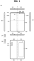
- FIG. 1 is a view illustrating an unfolded state of an electronic device according to certain embodiments of the disclosure.
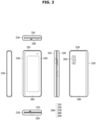
- FIG. 2 is a view illustrating a folded state of the electronic device according to certain embodiments of the disclosure.
- an electronic device 101 includes a foldable housing 300, a hinge cover (e.g., a hinge cover 330 of FIG. 2 ) provided to cover a foldable portion of the foldable housing 300, and a flexible or foldable display 200 (hereinafter referred to as "display" 200) arranged in a space formed by the foldable housing 300.
- a surface on which the display 200 is arranged is defined as a front surface of the electronic device 101.
- an opposite surface of the front surface is defined as a rear surface of the electronic device 101.
- a surface surrounding a space between the front surface and the rear surface is defined as a side surface of the electronic device 101.
- the foldable housing 300 may include a first housing structure 310, a second housing structure 320 including a sensor region 324, a first rear cover 380, a second rear cover 390, and a hinge structure (e.g., a hinge structure 500 of FIG. 3 ).
- the foldable housing 300 of the electronic device 101 is not limited to the shape and coupling shown in FIGS. 1 and 2 , and may be implemented by other shapes or other combination and/or coupling of components.
- the first housing structure 310 and the first rear cover 380 may be integrally formed
- the second housing structure 320 and the second rear cover 390 may be integrally formed.
- the first housing structure 310 may be connected to the hinge structure (e.g., the hinge structure 500 of FIG. 3 ), and include a first surface facing a first direction, and a second surface facing a second direction opposite the first direction.
- the second housing structure 320 may be connected to the hinge structure 500 and include a third surface facing a third direction and a fourth surface facing a fourth direction opposite to the third direction.
- the second housing structure 320 may be rotatable relative to the first housing structure 310 about the hinge structure 500.
- the electronic device 101 may be variable in form, and include both folded and unfolded configurations (e.g., folded and unfolded "state").
- the first surface of the electronic device 101 may be disposed to face the third surface in the folded state of the electronic device 101, and the third direction may be the same as the first direction in the unfolded state of the electronic device 101.
- the first housing structure 310 and the second housing structure 320 may be arranged on opposite sides about a folding axis (A-axis), and may have an overall symmetrical shape with respect to the folding axis A.
- A-axis folding axis
- an angle or a distance between the first housing structure 310 and the second housing structure 320 may vary depending on whether the electronic device 101 is in the folded state, or the unfolded state, or an intermediate state that is partially unfolded.
- the second housing structure 320 further includes a sensor region 324 in which various sensors are arranged, unlike the first housing structure 310, but in other region, the second housing structure 320 may have a shape symmetrical to the first housing structure 310.
- the first housing structure 310 and the second housing structure 320 may together form a recess for accommodating the display 200.
- the recess may have at least two different widths set in a direction perpendicular to the folding axis A.
- the recess may define a first width w1 between a first portion 310a, which is parallel to the folding axis A of the first housing structure 310, and a first portion 320a formed at a periphery of the sensor region 324 of the second housing structure 320.
- the recess may define a second width w2 between a second portion 310b of the first housing structure 310 and a second portion 320b of the second housing structure 320 that does not correspond to the sensor region 324 and is parallel to the folding axis A.
- the second width w2 may be formed to be greater than the first width w1.
- the first portion 310a of the first housing structure 310 and the first portion 320a of the second housing structure 320 having an asymmetrical shape may have the first width w1 of the recess.
- the second portion 310b of the first housing structure 310 and the second portion 320b of the second housing structure 320 having a symmetrical shape may have the second width w2 of the recess.
- a distance from the folding axis A to the first portion 320a may be different from a distance from the folding axis A the second portion 320b of the second housing structure 320.
- the width of the recess is not limited to the illustrated example.
- the recess may have a plurality of widths due to the shape of the sensor region 324 or due to a portion, which has the asymmetric shape, of the first housing structure 310 and the second housing structure 320.
- At least a portion of the first housing structure 310 and the second housing structure 320 may be formed of a metallic material or a non-metallic material having a rigidity sufficient to support the display 200.
- the at least a portion formed of the metal material may provide a ground plane of the electronic device 101 and be electrically connected to a ground line formed on a printed circuit board (e.g., a printed circuit board 520 of FIG. 3 ).
- the sensor region 324 may be formed to have a predetermined region adjacent to one corner of the second housing structure 320.
- an arrangement, shape, and size of the sensor region 324 are not limited to the illustrated example.
- the sensor region 324 may be provided at another corner of the second housing structure 320 or provided at any region between an upper corner and a lower corner.
- components for performing various functions and embedded in the electronic device 101 may be exposed on the front surface of the device 101 through the sensor region 324 or through one or more openings provided in the sensor region 324.
- the components may include various types of sensors.
- the sensor may include at least one of a front camera, a receiver, or a proximity sensor.
- the first rear cover 380 may be arranged on one side of the folding axis on the rear surface of the electronic device 101.
- the first rear cover 380 may include a substantially rectangular periphery, and the periphery may be surrounded by the housing structure 310.
- the second rear cover 390 may be arranged on the other side of the folding axis on the rear surface of the electronic device 101, and a periphery thereof may be surrounded by the second housing structure 320.
- the first rear cover 380 and the second rear cover 390 may have a substantially symmetrical shape with respect to the folding axis (A-axis).
- the first rear cover 380 and the second rear cover 390 do are not absolutely required to have symmetrical shapes, and in another embodiment, the electronic device 101 may include the first rear cover 380 and the second rear cover 390 formed in other various shapes.
- the first rear cover 380 may be integrally formed with the first housing structure 310
- the second rear cover 390 may be integrally formed with the second housing structure 320.
- the first rear cover 380, the second rear cover 390, the first housing structure 310, and the second housing structure 320 may form a space in which various components (e.g., a printed circuit board, or a battery) may be disposed.
- various components e.g., a printed circuit board, or a battery
- one or more components may be arranged or visually exposed on the rear surface of the electronic device 101.
- at least a portion of a sub-display may be visually exposed through a first rear region 382 of the first rear cover 380.
- one or more components or sensors may be visually exposed through a second rear region 392 of the second rear cover 390.
- the sensor may include a proximity sensor and/or a rear camera.
- the front camera which is exposed on the front surface of the electronic device 101 through one or more openings provided in the sensor region 324, or the rear camera, which is exposed through the second rear region 392 of the second rear cover 390 may include one or more lenses, an image sensor, and/or an image signal processor.
- a flash 313 may include a light emitting diode or a xenon lamp.
- two or more lenses (infrared cameras, wide angle and telephoto lenses) and image sensors may be arranged on one side of the electronic device 101.
- the hinge cover 330 may be arranged between the first housing structure 310 and the second housing structure 320 to cover internal components (e.g., the hinge structure 500 of FIG. 3 ). According to an embodiment, the hinge cover 330 may be covered by a portion of the first housing structure 310 and the second housing structure 320 or exposed to the outside according to the state of the electronic device 101, such as the unfolded state (or flat state), the intermediate state and the folded state.
- the hinge cover 330 when the electronic device 101 is configured in the unfolded state, the hinge cover 330 may be covered by the first housing structure 310 and the second housing structure 320 so as not to be exposed.
- the hinge cover 330 when the electronic device 101 is configured in the folded state (e.g., a fully folded state), the hinge cover 330 may be exposed to the outside through between the first housing structure 310 and the second housing structure 320.
- the hinge cover 330 in response to the intermediate state in which the first housing structure 310 and the second housing structure 320 are folded to a certain angle between 0 degrees and 180 degrees, the hinge cover 330 may be partially exposed to the outside through between the first housing structure 310 and the second housing structure 320.
- the exposed region may be less than that of the fully folded state.
- the hinge cover 330 may include a curved surface.
- the display 200 may be arranged in a space formed by the foldable housing 300.
- the display 200 is seated on the recess formed by the foldable housing 300 and may form most of the front surface of the electronic device 101.
- the front surface of the electronic device 101 may include the display 200, and a partial region of the first housing structure 310 and a partial region of the second housing structure 320 adjacent to the display 200.
- the rear surface of the electronic device 101 may include the first rear cover 380, a partial region of the first housing structure 310 adjacent to the first rear cover 380, the second rear cover 390, and a partial region of the second housing structure 320 adjacent to the second rear cover 390.
- the display 200 may include at least a region that is deformed into a flat surface or a curved surface.
- the display 200 may include a folding region 203, a first region 201 arranged on one side (e.g., the left side of the folding region 203 shown in FIG. 1 ) with respect to the folding region 203, and a second region 202 arranged on the other side (e.g., the right side of the folding region 203 shown in FIG. 1 ) with respect to the folding region 203.
- the division of the region of the display 200 shown in FIG. 1 is shown merely as an example, and the display 200 may be divided into a plurality (e.g., two or four or more) regions according to a structure or function.
- the region of the display 200 may be divided by the folding region 203 extending parallel to y-axis or the folding axis (A-axis), but in another embodiment, the display region 200 may be divided based on another folding region (e.g., a folding region parallel to x-axis) or another folding axis (e.g., a folding axis parallel to x-axis).
- the display 200 may be coupled to or arranged adjacent to a touch sensing circuit, a pressure sensor may be configured to measure an intensity (pressure) of a touch, and/or a digitizer may also be provided to detect a magnetic field type stylus pen.
- the display 200 may include a display panel (e.g., a flexible display panel) and one or more plates or layers (e.g., a support plate 240) on which the display panel is mounted.
- the support plate 240 may be arranged between the display panel and the bracket assembly 400.
- An adhesive structure (not shown) may be positioned between the support plate 240 and the bracket assembly 400 to bond the support plate 240 and the bracket assembly 400.
- the bracket assembly 400 may include a first support plate 410 and a second support plate 420.
- the hinge structure 500 may be arranged between the first support plate 410 and the second support plate 420, and the hinge cover 330 that is provided to cover the hinge structure 500 when the hinge structure 500 is viewed from the outside may be disposed between the first support plate 410 and the second support plate 420.
- a printed circuit board e.g., a flexible printed circuit board (FPC)
- FPC flexible printed circuit board
- the first housing structure 310 and the second housing structure 320 may be coupled to opposite sides of the bracket assembly 400 in response to coupling the display 200 to the bracket assembly 400.
- the first housing structure 310 and the second housing structure 320 may slide from opposite sides of the bracket assembly 400 so as to be coupled to the bracket assembly 400.
- the first housing structure 310 may include a first rotation support surface 313, and the second housing structure 320 may include a second rotation support surface 323 corresponding to the first rotation support surface 313.
- the first rotation support surface 313 and the second rotation support surface 323 may include a curved surface corresponding to the curved surface included in the hinge cover 330.
- the electronic device 101 may include the hinge structure 500 which operably connects the first housing 310 to the second housing 320.
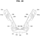
- the hinge structure 500 may include a hinge body 512 coupled to the first axis shaft 511 and the second axis shaft 561.
- the hinge body 512 may include a first body guide 513a coupled to the first coupling portion guide 515 to guide movement of the first coupling portion guide 515, and a second body guide 513b coupled to the second coupling portion guide 565 to guide movement of the second coupling portion guide 565.
- FIG. 6 illustrates that two first shaft gears 516 and two second shaft gears 566 are provided on opposite sides of the hinge body 512, respectively, but if the first axis shaft 511 and the second shaft gear 566 are provided to be rotated in directions opposite to each other, it is understood that the number of shaft gears is not limited to the description provided herein.
- the hinge structure 500 may include a shaft bracket 519 provided to rotatably support ends of the first axis shaft 511 and the second axis shaft 561. As the shaft bracket 519 is rotatably coupled to the first axis shaft 511 and the second axis shaft 561, it is possible to prevent the components coupled to the first axis shaft 511 and the second axis shaft 561 from being separated.
- the first housing 310 and the second housing 320 may be rotated.
- the hinge structure 500 is provided such that the components interlocked with the first axis shaft 511 are approximately symmetrical with the components interlocked with the second axis shaft 561, for convenience of description, a configuration related to the first axis shaft 511 will be described in detail, and a configuration related to the second axis shaft 561 will be omitted but for brief descriptions thereof, in the interests of brevity. Further, components interlocked with the first axis shaft 511 are approximately symmetrical with the first housing coupling portion 514, and for convenience of description, components located on one side of the first housing coupling portion 514 will be described.
- the hinge structure 500 may include sliding cams 591, 592, 593, and 594 rotatably and slidably coupled to the second axis shaft 561.
- the sliding cams 591, 592, 593, and 594 may include a fifth sliding cam 591, a sixth sliding cam 592, a seventh sliding cam 593, and an eighth sliding cam 594.
- the fifth sliding cam 591, the sixth sliding cam 592, the seventh sliding cam 593, and the eighth sliding cam 594 may correspond to the first sliding cam 541, the second sliding cam 542, the third sliding cam 543, and the fourth sliding cam 544, respectively.
- the hinge structure 500 may include a third bridge 543b extending between the third sliding cam 543 and the seventh sliding cam 593.
- the third sliding cam 543 may slide without rotating even when the first axis shaft 511 is rotated
- the seventh sliding cam 593 may slide without rotating even when the second axis shaft 561 is rotated.
- the hinge structure 500 may include a fourth bridge 544b extending between the fourth sliding cam 544 and the eighth sliding cam 594.
- the fourth bridge 544b the fourth sliding cam 544 may slide without rotating even when the first axis shaft 511 is rotated
- the eighth sliding cam 594 may slide without rotating even when the second axis shaft 561 is rotated.
- the first sliding cam 541 is engaged with a first rotation cam 531
- the second sliding cam 542 and the third sliding cam 543 are engaged with a second rotation cam 532
- the fourth sliding cam 544 may be engaged with a third rotation cam 533.
- the fifth sliding cam 591 may be engaged with a fourth rotation cam 581
- the sixth sliding cam 592 and the seventh sliding cam 593 may be engaged with a fifth rotation cam 582
- the eighth sliding cam 594 may be engaged with a sixth rotation cam 583.
- the first sliding cam 541 includes a first sliding cam nose 541a.
- the first sliding cam nose 541a may be a protruding portion of the first sliding cam 541, and is formed to engage and interact with a first rotation cam nose 531a of the first rotation cam 531.
- the second sliding cam 542 includes a second sliding cam nose 542a.
- the second sliding cam nose 542a may be a protruding portion of the second sliding cam 542, and is formed to engage and interact with a second rotation cam nose 532a of the second rotation cam 532.
- the third sliding cam 543 includes a third sliding cam nose 543a.
- the third sliding cam nose 543a may be a protruding portion of the third sliding cam 543, and is formed to engage and interact with a third rotation cam nose 532b of the second rotation cam 532.
- the fourth sliding cam 544 includes a fourth sliding cam nose 544a.
- the fourth sliding cam nose 544a may be a protruding portion of the fourth sliding cam 544, and is formed to engage and interact with a fourth rotation cam nose 533a of the third rotation cam 533.
- the fifth sliding cam 591 may include a fifth sliding cam nose 591a.
- the sixth sliding cam 592 may include a sixth sliding cam nose 592a.
- the seventh sliding cam 593 may include a seventh sliding cam nose 593a.
- the eighth sliding cam 594 may include an eighth sliding cam nose 594a.
- the fifth sliding cam nose 591a, the sixth sliding cam nose 592a, the seventh sliding cam nose 593a, and the eighth sliding cam nose 594a may correspond to the first sliding cam nose 541a, the second sliding cam nose 542a, the third sliding cam nose 543a, and the fourth sliding cam nose 544a, respectively.
- the first sliding cam nose 541a, the second sliding cam nose 542a, the third sliding cam nose 543a, and the fourth sliding cam nose 544a may be provided at an approximately same position along a radial direction from the first axis shaft 511.
- the first sliding cam nose 541a, the second sliding cam nose 542a, the third sliding cam nose 543a, and the fourth sliding cam nose 544a may be located on approximately a same (imaginary) line.
- a first elastic member 546 is provided between the first sliding cam 541 and the second sliding cam 542.
- the first elastic member 546 may be provided to apply an elastic force, along a direction in which the first sliding cam 541 and the second sliding cam 542 are movable away from each other, towards the first sliding cam 541 and the second sliding cam 542.
- the first sliding cam 541 and the second sliding cam 542 are configured to share the first elastic member 546, it is possible to reduce a size thereof in comparison with a state in which an elastic member provided to elastically press the first sliding cam 541 toward the first rotation cam 531 and an elastic member provided to elastically press the second sliding cam 542 toward the second rotation cam 532 are respectively provided.
- a second elastic member 547 is provided between the third sliding cam 543 and the fourth sliding cam 544.
- the second elastic member 547 may be provided to apply an elastic force, along a direction in which the third sliding cam 543 and the fourth sliding cam 544 are movable away from each other, towards the third sliding cam 543 and the fourth sliding cam 544.
- the first sliding cam 541 and the second sliding cam 542 are configured to share the first elastic member 546
- the third sliding cam 543 and the fourth sliding cam 544 are configured to share the second elastic member 547, and thus it is possible to reduce a size thereof in comparison with a state in which an elastic member for the first sliding cam 541, an elastic member for the second sliding cam 542, an elastic member for the third sliding cam 543 and an elastic member for the fourth sliding cam 544 are individually provided.
- a third elastic member 596 may be provided between the fifth sliding cam 591 and the sixth sliding cam 592.
- the third elastic member 596 may be provided to apply an elastic force, along a direction in which the fifth sliding cam 591 and the sixth sliding cam 592 are movable away from each other, towards the fifth sliding cam 591 and the sixth sliding cam 592.
- the third elastic member 596 may correspond to the first elastic member 546.
- a fourth elastic member 597 may be provided between the seventh sliding cam 593 and the eighth sliding cam 594.
- the fourth elastic member 597 may be provided to apply an elastic force, along a direction in which the seventh sliding cam 593 and the eighth sliding cam 594 are movable away from each other, towards the seventh sliding cam 593 and the eighth sliding cam 594.
- the fourth elastic member 597 may correspond to the second elastic member 547.
- the hinge structure 500 includes a first cam body 530 coupled to the first housing coupling portion 514.
- the first cam body 530 may be coupled to the first housing coupling portion 514 by a first sliding shaft 518.
- the first sliding shaft 518 may be rotatably coupled to the first cam body 530.
- the first sliding shaft 518 may be slidably coupled to the first housing coupling portion 514.
- the first sliding shaft 518 may guide the first housing coupling portion 514 to allow the first housing coupling portion 514 to be rotated and moved in response to rotation of the first cam body 530.
- the hinge structure 500 may include a second cam body 580 coupled to the second housing coupling portion 564.
- the second cam body 580 may be coupled to the second housing coupling portion 564 by a second sliding shaft 568.
- the second cam body 580 and the second sliding shaft 568 may correspond to the first cam body 530 and the first sliding shaft 518.
- the first cam body 530 includes the first rotation cam 531, the second rotation cam 532, and the third rotation cam 533.
- the first rotation cam 531, the second rotation cam 532, and the third rotation cam 533 may be fixed to the first axis shaft 511 to be rotatable together with the first axis shaft 511.
- the first rotation cam 531 engages and interacts with the first sliding cam 541.
- the second rotation cam 532 engages and interacts with the second sliding cam 542, and the third sliding cam 543.
- the third rotation cam 533 engages and interacts with the fourth sliding cam 544.
- the second cam body 580 may include the fourth rotation cam 581, the fifth rotation cam 582, and the sixth rotation cam 583.
- the fourth rotation cam 581, the fifth rotation cam 582, and the sixth rotation cam 583 may correspond to the first rotation cam 531, the second rotation cam 532, and the third rotation cam 533, respectively.
- the first rotation cam 531 includes the first rotation cam nose 531a.
- the first rotation cam nose 531a is a protruding portion of the first rotation cam 531, and is formed to engage and interact with the first sliding cam nose 541a of the first sliding cam 541.
- the second rotation cam 532 includes the second rotation cam nose 532a and the third rotation cam nose 532b.
- the second rotation cam nose 532a is a protruding portion of the second rotation cam 532, and is formed to engage and interact with the second sliding cam nose 542a of the second sliding cam 542.
- the third rotation cam nose 532b is a protruding portion of the second rotation cam 532, and is formed to engage and interact with the third sliding cam nose 543a of the third sliding cam 543.
- the second rotation cam 532 may be formed in such a way that the second rotation cam nose 532a is formed on one surface facing the second sliding cam 542, and the third rotation cam nose 532b is formed on one surface facing the third sliding cam 543.
- the third rotation cam nose 532b may be formed on a surface opposite to the surface on which the second rotation cam nose 532a is formed.
- the third rotation cam 533 includes the fourth sliding cam nose 533a.
- the fourth rotation cam nose 533a is a protruding portion of the third rotation cam 533, and is formed to engage and interact with the fourth sliding cam nose 544a of the fourth sliding cam 544.
- the fourth rotation cam 581 may include the fifth rotation cam nose 581a.
- the fifth rotation cam 582 may include the sixth rotation cam nose 582a and the seventh rotation cam nose 582b.
- the sixth rotation cam 583 may include the eighth sliding cam nose 583a.
- the fifth rotation cam nose 581a, the sixth rotation cam nose 582a, the seventh rotation cam nose 582b, and the eighth rotation cam nose 583a may correspond to the first rotation cam nose 531a, the second rotation cam nose 532a, the third rotation cam nose 532b, and the fourth rotation cam nose 533a, respectively.
- the first rotation cam 531 may be moved according to a relative position of the first rotation cam nose 531a with respect to the first sliding cam nose 541a of the first sliding cam 541.
- the second rotation cam 532 may be moved according to a relative position of the second rotation cam nose 532a with respect to the second sliding cam nose 542a of the second sliding cam 542 or according to a relative position of the third rotation cam nose 532b with respect to the third sliding cam nose 543a of the third sliding cam 543.
- the fourth rotation cam 581 may be moved according to a relative position of the fourth rotation cam nose 533a with respect to the fourth sliding cam nose 544a of the fourth sliding cam 544.
- the first rotation cam nose 531a, the second rotation cam nose 532a, the third rotation cam nose 532b, and the fourth sliding cam nose 533a are arranged at different positions from each other along the radial direction from the first axis shaft 511.
- the first rotation cam nose 531a, the second rotation cam nose 532a, the third rotation cam nose 532b, and the fourth rotation cam nose 533a are located on different lines from each other.
- the first sliding cam nose 541a, the second sliding cam nose 542a, the third sliding cam nose 543a, and the fourth sliding cam nose 544a are extended to be positioned on the same line.
- the first rotation cam nose 531a, the second rotation cam nose 532a, the third rotation cam nose 532b, and the fourth rotation cam nose 533a are extended to be positioned on different lines from each other. That is, an imaginary line, on which the first rotation cam nose 531a is extended, is different from imaginary lines on which the second rotation cam nose 532a, the third rotation cam nose 532b, and the fourth rotation cam nose 533a are extended.
- An imaginary line, on which the second rotation cam nose 532a is extended, is different from imaginary lines on which the third rotation cam nose 532b, and the fourth rotation cam nose 533a are extended.
- An imaginary line, on which the third rotation cam nose 532b is extended, is different from an imaginary line on which the fourth rotation cam nose 533a is extended.
- a position in which the first rotation cam nose 531a interacts with the first sliding cam nose 541a is different from a position in which the second rotation cam nose 532a interacts with the second sliding cam nose 542a, a position in which the third rotation cam nose 532b interacts with the third sliding cam nose 543a and a position in which the fourth rotation cam nose 533a interacts with the fourth sliding cam nose 544a.
- the position in which the second rotation cam nose 532a interacts with the second sliding cam nose 542a is different from the position in which the third rotation cam nose 532b interacts with the third sliding cam nose 543a and the position in which the fourth rotation cam nose 533a interacts with the fourth sliding cam nose 544a.
- the position in which the third rotation cam nose 532b interacts with the third sliding cam nose 543a is different from the position in which the fourth rotation cam nose 533a interacts with the fourth sliding cam nose 544a.
- the hinge structure 500 may set various stopping angles between the first housing 310 and the second housing 320 by variously combining the position in which the first rotation cam nose 531a interacts with the first sliding cam nose 541a, the position in which the second rotation cam nose 532a interacts with the second sliding cam nose 542a, the position in which the third rotation cam nose 532b interacts with the third sliding cam nose 543a and the position in which the fourth rotation cam nose 533a interacts with the fourth sliding cam nose 544a.
- the configuration will be described in detail with reference to FIGS. 7 to 16 .
- FIG. 7 is a rear view illustrating an unfolded state of the hinge structure provided in the electronic device according to certain embodiments of the disclosure.
- FIG. 8 is an enlarged view of part A shown in FIG. 7 .
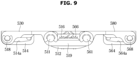
- FIG. 9 is a side view illustrating the unfolded state of the hinge structure provided in the electronic device according to certain embodiments of the disclosure.
- the hinge structure 500 may be set in the unfolded state.
- the first rotation cam nose 531a of the first rotation cam 531 is disposed as to contact and interact with the first sliding cam nose 541a of the first sliding cam 541. That is, an end of the first rotation cam nose 531a is out of a flat section of the first sliding cam 541 and is in a position proximate to the end of the first sliding cam nose 541a.
- the second rotation cam nose 532a of the second rotation cam 532 is in a position in which the second rotation cam nose 532a does not come into contact so as not to interact with the second sliding cam nose 542a of the second sliding cam 542.
- the third rotation cam nose 532b of the second rotation cam 532 is in a position in which the third rotation cam nose 532b does not come into contact so as not to interact with the third sliding cam nose 543a of the third sliding cam 543.
- the fourth rotation cam nose 533a of the third rotation cam 533 is in a position in which the fourth rotation cam nose 533a does not come into contact so as not to interact with the fourth sliding cam nose 544a of the fourth sliding cam 544.
- the end of the second rotation cam nose 532a is spaced apart from the second sliding cam nose 542a and is located in a flat section of the second sliding cam 542.
- the end of the third rotation cam nose 532b is spaced apart from the third sliding cam nose 543a and is located in a flat section of the third sliding cam 543.
- the end of the fourth rotation cam nose 533a is spaced apart from the fourth sliding cam nose 544a and is located in a flat section of the fourth sliding cam 544.
- the first elastic member 546 may apply a force to the first sliding cam 541 in a direction in which the first sliding cam 541 moves away from the second sliding cam 542 (i.e., R-direction in FIG. 7 ). That is, the first sliding cam 541 receives a force in a direction proximate to the first rotation cam 531. Accordingly, the first rotation cam nose 531a receives a force causing it to move to a position, in which the end of the first rotation cam nose 531a is moved away from the end of the first sliding cam nose 541a so as not to interact with the first sliding cam nose 541a (e.g., in FIG.
- the first rotation cam nose 531a in contact with an upper surface of the first sliding cam nose 541a receives a force that is to move further upward toward the flat section of the first sliding cam 541). That is, the first rotation cam 531 receives a force along a direction in which the first housing 310 and the second housing 320 unfolded relative to each other.
- the first housing coupling portion 514 coupled to the first cam body 530 is in a state, in which, during rotation in a direction as to unfold the device (e.g., in FIG. 7 , the first rotation cam nose 531a in contact with the upper surface of the first sliding cam nose 541a is rotated in a direction of moving further upward toward the flat section of the first sliding cam 541) is limited by the hinge body 512, and thus the rotation of the first rotation cam 531 for separating the first housing 310 and the second housing 320 into the unfolded state is limited. That is, in the first rotation cam 531, an elastic force received from the first elastic member 546 and a force supported by the hinge body 512 are balanced, and thus the first rotation cam nose 531a may maintain a position with respect to the first sliding cam nose 541a.
- the sliding cams 591, 592, 593, and 594 coupled to the second axis shaft 561 and the rotation cams 581, 582, and 583 engaged therewith are operated in the same manner as the above-mentioned sliding cams 541, 542, 543, and 544 coupled to the first axis shaft 511 and the rotation cams 531, 532, and 533 engaged therewith, and thus a detailed description thereof will be omitted.
- FIG. 10 is a rear view illustrating a state in which the hinge structure provided in the electronic device is fixed at a first angle according to certain embodiments of the disclosure.
- FIG. 11 is an enlarged view of part B shown in FIG. 10 .
- FIG. 12 is a side view illustrating the state in which the hinge structure provided in the electronic device is fixed at the first angle according to certain embodiments of the disclosure.
- the hinge structure 500 may be fixed at a position in which the first housing 310 and the second housing 320 form approximately a 130° angle.
- the angle shown in FIG. 10 may be referred to as a first angle.
- the first rotation cam nose 531a of the first rotation cam 531 may cross the end of the first sliding cam nose 541a of the first sliding cam 541, and may be moved in the opposite direction (e.g., in the case of the first rotation cam nose 531a in contact with the upper surface of the first sliding cam nose 541a in FIG. 7 , it is downward). Because the first elastic member 546 applies a force in a direction in which the first sliding cam 541 moves away from the second sliding cam 542, the first sliding cam 541 may receive a force having directionality towards the first rotation cam 531(R-direction in FIG. 10 ). That is, the first rotation cam nose 531a receives a force having directionality pointing away from the end of the first sliding cam nose 541a.
- the first rotation cam 531 may receive a force in the direction in which the first housing 310 and the second housing 320 are folded (a direction in which the first rotation cam nose 531a in contact with a lower surface of the first sliding cam nose 541a in FIG. 10 is further moved downward).
- the third rotation cam nose 532b of the second rotation cam 532 may be disposed in a position of contacting and interacting with the third sliding cam nose 543a of the third sliding cam 543.
- the third rotation cam nose 532b may receive a force in a direction away from the third sliding cam nose 543a. That is, the second rotation cam 532 receives a force in the direction by which the first housing 310 and the second housing 320 are unfolded (a direction in which the third rotation cam nose 532b in contact with the upper surface of the third sliding cam nose 543a in FIG. 10 is moved further upwards).
- the rotational force applied to the first cam body 530 may be balanced. Accordingly, the positions of the first housing 310 and the second housing 320 may be fixed without unfolding or folding.
- the second rotation cam nose 532a of the second rotation cam 532 and the second sliding cam nose 542a of the second sliding cam 542 are located in positions in which the second rotation cam nose 532a and the second sliding cam nose 542a are not in contact with each other and do not interact with each other. That is, the second rotation cam nose 532a is positioned in a flat section of the second sliding cam 542, and the second sliding cam nose 542a is positioned in a flat section of the second rotation cam 532.
- the fourth rotation cam nose 533a of the third rotation cam 533 and the fourth sliding cam nose 544a of the fourth sliding cam 544 are located in positions in which the fourth rotation cam nose 533a and the fourth sliding cam nose 544a are not in contact with each other and do not interact with each other. That is, the fourth rotation cam nose 533a is positioned in a flat section of the fourth sliding cam 544, and the fourth sliding cam nose 544a is positioned in the flat section of the second rotation cam 532.
- the sliding cams 591, 592, 593, and 594 coupled to the second axis shaft 561 and the rotation cams 581, 582, and 583 engaged therewith are operated in the same manner as the above-mentioned sliding cams 541, 542, 543, and 544 coupled to the first axis shaft 511 and the rotation cams 531, 532, and 533 engaged therewith, and thus a detailed description thereof will be omitted.
- FIG. 13 is a rear view illustrating a state in which the hinge structure provided in the electronic device is fixed at a second angle according to certain embodiments of the disclosure.
- FIG. 14 is an enlarged view of part C shown in FIG. 13 .
- FIG. 15 is a side view illustrating the state in which the hinge structure provided in the electronic device is fixed at the second angle according to certain embodiments of the disclosure.
- the hinge structure 500 may be fixed at a position in which an angle between the first housing 310 and the second housing 320 forms approximately 90°.
- the angle shown in FIG. 13 may be referred to as a second angle.
- the first rotation cam nose 531a is moved to a position in which the first rotation cam nose 531a is not in contact with and does not interact with the first sliding cam nose 541a.
- the second rotation cam nose 532a is moved to a position of contacting and interacting with the second sliding cam nose 542a. That is, the second rotation cam nose 532a is out of the flat section of the second sliding cam 542 and is in a position close to the end of the second sliding cam nose 542a. Accordingly, referring to FIG. 13 , the first sliding cam 541, the second sliding cam 542, and the first elastic member 546 are moved together in the R-direction.
- the rotational force applied to the first cam body 530 is balanced. Accordingly, the positions of the first housing 310 and the second housing 320 may be fixed without folding or unfolding.
- the fourth rotation cam nose 533a of the third rotation cam 533 is located in a position in which the fourth rotation cam nose 533a is not in contact with and does not interact with the fourth sliding cam nose 544a. That is, the fourth rotation cam nose 533a is positioned in a flat section of the fourth sliding cam 544.
- the first sliding shaft 518 slides along the guide slit 514a of the first housing coupling portion 514, and the first coupling portion guide 515 is guided by the first body guide 513a. Accordingly, the first housing coupling portion 514 is rotated and moved in a direction in which the hinge cover 330 is exposed.
- the sliding cams 591, 592, 593, and 594 coupled to the second axis shaft 561 and the rotation cams 581, 582, and 583 engaged therewith are operated in the same manner as the above-mentioned sliding cams 541, 542, 543, and 544 coupled to the first axis shaft 511 and the rotation cams 531, 532, and 533 engaged therewith, and thus a detailed description thereof will be omitted.
- the third rotation cam nose 532b is moved to a position in which the third rotation cam nose 532b is not in contact with and does not interact with the third sliding cam nose 543a.
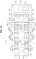
- the fourth rotation cam nose 533a is moved to a position of contacting and interacting with the fourth sliding cam nose 544a. That is, the fourth rotation cam nose 533a is out of the flat section of the fourth sliding cam 544 and is in a position close to the end of the fourth sliding cam nose 544a. Accordingly, referring to FIG. 16 , the fourth sliding cam 544, the third sliding cam 543, and the second elastic member 547 are moved together in the R-direction.
- the fourth sliding cam 544 receives a force in a direction closer to the third rotation cam 533. Accordingly, the fourth rotation cam nose 533a receives a force in a direction away from the end of the fourth sliding cam nose 544a. That is, referring to FIG. 16 , the fourth rotation cam nose 533a in contact with the upper surface of the fourth sliding cam nose 544a receives a force in a direction of moving further upward (the direction in which the first housing 310 and the second housing 320 are unfolded).
- the second rotation cam nose 532a crosses the end of the second sliding cam nose 542a and is moved to the opposite direction. That is, the second rotation cam nose 532a in contact with the upper surface of the second sliding cam nose 542a as shown in FIG. 13 is moved to contact the lower surface of the second sliding cam nose 542a, as shown in FIG. 16 . Because the first elastic member 546 applies a force in a direction in which the second sliding cam 542 is away from the first sliding cam 541, the second sliding cam 542 receives a force in a direction closer to the second rotation cam 532. Accordingly, the second rotation cam nose 532a receives a force in a direction away from the end of the second sliding cam nose 542a (the direction in which the first housing 310 and the second housing 320 are folded).
- the rotational force applied to the first cam body 530 is balanced. Accordingly, the positions of the first housing 310 and the second housing 320 may be fixed without folding or unfolding.
- the first sliding shaft 518 slides along the guide slit 514a of the first housing coupling portion 514, and the first coupling portion guide 515 is guided by the first body guide 513a. Accordingly, the first housing coupling portion 514 is rotated and moved in a direction in which the hinge cover 330 is exposed.
- the sliding cams 591, 592, 593, and 594 coupled to the second axis shaft 561 and the rotation cams 581, 582, and 583 engaged therewith are operated in the same manner as the above-mentioned sliding cams 541, 542, 543, and 544 coupled to the first axis shaft 511 and the rotation cams 531, 532, and 533 engaged therewith, and thus a detailed description thereof will be omitted.
- FIG. 19 is a rear view illustrating a folded state of the hinge structure provided in the electronic device according to certain embodiments of the disclosure.
- FIG. 20 is an enlarged view of part E shown in FIG. 19 .
- FIG. 21 is a side view illustrating the folded state of the hinge structure provided in the electronic device according to certain embodiments of the disclosure.
- the hinge structure 500 may be fixed in the state in which the first housing 310 and the second housing 320 are folded.
- the second rotation cam nose 532a is moved to a position in which the second rotation cam nose 532a is not in contact with and does not interact with the second sliding cam nose 542a. That is, the second rotation cam nose 532a is positioned in a flat section of the second sliding cam 542.
- the fourth rotation cam nose 533a may cross the end of the fourth sliding cam nose 544a and is moved to the opposite direction. That is, the fourth rotation cam nose 533a may be in contact with the upper surface of the fourth sliding cam nose 544a as shown in FIG. 16 , and may be moved to contact the lower surface of the fourth sliding cam nose 544a, as shown in FIG. 19 . Because the second elastic member 547 applies a force in a direction in which the fourth sliding cam 544 is moved away from the third sliding cam 543, the fourth sliding cam 544 receives a force in a direction coming closer to the fourth rotation cam 533. Accordingly, the fourth rotation cam nose 533a receives a force in a direction away from the end of the fourth sliding cam nose 544a (the direction in which the first housing 310 and the second housing 320 are folded).
- the first sliding shaft 518 may slide along the guide slit 514a of the first housing coupling portion 514, and the first coupling portion guide 515 is guided by the first body guide 513a. Accordingly, the first housing coupling portion 514 is rotated and moved in a direction in which the first region 201 and the second region 202 of the display 200 are closed to each other.
- the sliding cams 591, 592, 593, and 594 coupled to the second axis shaft 561 and the rotation cams 581, 582, and 583 engaged therewith are operated in the same manner as the above-mentioned sliding cams 541, 542, 543, and 544 coupled to the first axis shaft 511 and the rotation cams 531, 532, and 533 engaged therewith, and thus a detailed description thereof will be omitted.
- each component e.g., a module or a program of the above-described components may include a singular or a plurality of entities, and some of the plurality of entities may be separately arranged in other components.
- one or more components or operations among the above-described corresponding components may be omitted, or one or more other components or operations may be added.
- a plurality of components e.g., a module or a program
- the integrated component may perform one or more functions of each component of the plurality of components identically or similarly to those performed by the corresponding component among the plurality of components prior to the integration.
- Operations performed by a module, a program module, or other elements according to certain embodiments of the present disclosure may be executed sequentially, in parallel, repeatedly, or in a heuristic method. Also, a portion of operations may be executed in different sequences, omitted, or other operations may be added.
Landscapes
- Engineering & Computer Science (AREA)
- Theoretical Computer Science (AREA)
- Computer Hardware Design (AREA)
- Physics & Mathematics (AREA)
- General Physics & Mathematics (AREA)
- Human Computer Interaction (AREA)
- General Engineering & Computer Science (AREA)
- Signal Processing (AREA)
- Mathematical Physics (AREA)
- Telephone Set Structure (AREA)
Claims (11)
- Dispositif électronique (101), comprenant :un affichage flexible (200) comprenant une première zone (201) et une seconde zone (202) ;un premier boîtier (310) supportant la première zone (201) ;un second boîtier (320) supportant la seconde zone (202) ; etune structure de charnière (500) reliant le premier boîtier (310) au second boîtier (320), dans lequel la structure de charnière (500) comprend :un arbre d'axe (511) formant un axe de rotation ;une came coulissante (541, 542, 543, 544) couplée de manière coulissante à l'arbre d'axe (511), et comprenant une première came coulissante (541) dans laquelle un premier nez de came coulissante (541a) est formé, une deuxième came coulissante (542) dans laquelle un deuxième nez de came coulissante (542a) est formé, une troisième came coulissante (543) dans laquelle un troisième nez de came coulissante (543a) est formé, et une quatrième came coulissante (544) dans laquelle un quatrième nez de came coulissante (544a) est formé ;un corps de came comprenant une première came de rotation (531) comprenant un premier nez de came de rotation (531a) en prise avec la première came coulissante (541), une deuxième came de rotation (532) comprenant un deuxième nez de came de rotation (532a) en prise avec la deuxième came coulissante (542) et un troisième nez de came de rotation (532b) en prise avec la troisième came coulissante (543), et une troisième came de rotation (533) comprenant un quatrième nez de came de rotation (533a) en prise avec la quatrième came coulissante (544) ; etdes éléments élastiques comprenant un premier élément élastique (546) disposé entre la première came coulissante (541) et la deuxième came coulissante (542), et un second élément élastique (547) disposé entre la troisième came coulissante (543) et la quatrième came coulissante (544),dans lequel le premier nez de came de rotation (531a), le deuxième nez de came de rotation (532a), le troisième nez de came de rotation (532b) et le quatrième nez de came de rotation (533a) sont disposés sur différentes lignes imaginaires s'étendant parallèlement à l'axe de rotation de l'arbre d'axe (511), etdans lequel le premier nez de came coulissante (541a), le deuxième nez de came coulissante (542a), le troisième nez de came coulissante (543a) et le quatrième nez de came coulissante (544a) sont disposés sur une même ligne imaginaire.
- Dispositif électronique (101) selon la revendication 1, dans lequel :le premier élément élastique (546) applique une force élastique à la première came coulissante (541) et à la deuxième came coulissante (542), le long d'une direction dans laquelle la première came coulissante (541) est mobile en s'éloignant de la deuxième came coulissante (542) ; etle second élément élastique (547) applique une force élastique à la troisième came coulissante (543) et à la quatrième came coulissante (544), le long d'une direction dans laquelle la troisième came coulissante (543) est mobile en s'éloignant de la quatrième came coulissante (544).
- Dispositif électronique (101) selon la revendication 1, dans lequel :
le corps de came peut tourner conjointement à l'arbre d'axe (511). - Dispositif électronique (101) selon la revendication 1, dans lequel :
lorsque le premier boîtier (310) et le second boîtier (320) sont disposés selon un premier angle l'un par rapport à l'autre, la première came de rotation (531) est configurée pour recevoir une force de rotation dans une première direction par le premier élément élastique (546) et la première came coulissante (541), et la troisième came de rotation (533) est configurée pour recevoir une force de rotation dans une deuxième direction opposée à la première direction par le second élément élastique (547) et la troisième came coulissante (543). - Dispositif électronique (101) selon la revendication 4, dans lequel :
lorsque le premier boîtier (310) et le second boîtier (320) sont disposés selon un deuxième angle l'un par rapport à l'autre, la deuxième came de rotation (532) est configurée pour recevoir une force de rotation dans la deuxième direction par le premier élément élastique (546) et la deuxième came coulissante (542), et la troisième came de rotation (533) est configurée pour recevoir une force de rotation dans la première direction par le second élément élastique (547) et la troisième came coulissante (543). - Dispositif électronique (101) selon la revendication 5, dans lequel :
lorsque le premier boîtier (310) et le second boîtier (320) sont disposés selon un troisième angle l'un par rapport à l'autre, la deuxième came de rotation (532) est configurée pour recevoir une force de rotation dans la première direction par le premier élément élastique (546) et la deuxième came coulissante (542), et la troisième came de rotation (533) est configurée pour recevoir une force de rotation dans la deuxième direction par le second élément élastique (547) et la quatrième came coulissante (544). - Dispositif électronique (101) selon la revendication 6, dans lequel :
le premier angle est supérieur au deuxième angle, et le deuxième angle est supérieur au troisième angle. - Dispositif électronique (101) selon la revendication 6, dans lequel :
lorsque le premier boîtier (310) et le second boîtier (320) sont tournés selon un angle compris entre le premier angle et le deuxième angle, la première came coulissante (541), la deuxième came coulissante (542) et le premier élément élastique (546) sont déplacés le long d'une direction dans laquelle l'arbre d'axe (511) s'étend. - Dispositif électronique (101) selon la revendication 6, dans lequel :
lorsque le premier boîtier (310) et le second boîtier (320) sont tournés selon un angle compris entre le deuxième angle et le troisième angle, la troisième came coulissante (543), la quatrième came coulissante (544) et le second élément élastique (547) sont déplacés le long d'une direction dans laquelle l'arbre d'axe (511) s'étend. - Dispositif électronique (101) selon la revendication 1, dans lequel :
lorsque le premier boîtier (310) et le second boîtier (320) sont disposés dans une configuration dépliée, le premier nez de came de rotation (531a) est supporté sur le premier nez de came coulissante (541a) par le premier élément élastique (546), dans une direction le long de laquelle le premier boîtier (310) et le second boîtier (320) se déplient l'un par rapport à l'autre. - Dispositif électronique (101) selon la revendication 1, dans lequel :
lorsque le premier boîtier (310) et le second boîtier (320) sont disposés dans une configuration repliée, le quatrième nez de came de rotation (533a) est supporté sur le quatrième nez de came coulissante (544a) par le second élément élastique (547), dans une direction le long de laquelle le premier boîtier (310) et le second boîtier (320) se replient ensemble.
Applications Claiming Priority (2)
| Application Number | Priority Date | Filing Date | Title |
|---|---|---|---|
| KR1020210004474A KR20220102288A (ko) | 2021-01-13 | 2021-01-13 | 접이식 플렉서블 디스플레이 장치 및 전자 장치 |
| PCT/KR2021/017544 WO2022154249A1 (fr) | 2021-01-13 | 2021-11-25 | Dispositif d'affichage flexible pliable et dispositif électronique |
Publications (3)
| Publication Number | Publication Date |
|---|---|
| EP4207144A1 EP4207144A1 (fr) | 2023-07-05 |
| EP4207144A4 EP4207144A4 (fr) | 2024-03-27 |
| EP4207144B1 true EP4207144B1 (fr) | 2025-03-12 |
Family
ID=82321796
Family Applications (1)
| Application Number | Title | Priority Date | Filing Date |
|---|---|---|---|
| EP21919873.6A Active EP4207144B1 (fr) | 2021-01-13 | 2021-11-25 | Dispositif d'affichage flexible pliable et dispositif électronique |
Country Status (2)
| Country | Link |
|---|---|
| US (1) | US11983047B2 (fr) |
| EP (1) | EP4207144B1 (fr) |
Families Citing this family (9)
| Publication number | Priority date | Publication date | Assignee | Title |
|---|---|---|---|---|
| TWI811583B (zh) * | 2020-11-09 | 2023-08-11 | 宏碁股份有限公司 | 鉸鏈組件及可攜式電子裝置 |
| CN112738308B (zh) * | 2020-12-30 | 2023-05-09 | 维沃移动通信有限公司 | 折叠机构及折叠式电子设备 |
| EP4207144B1 (fr) * | 2021-01-13 | 2025-03-12 | Samsung Electronics Co., Ltd. | Dispositif d'affichage flexible pliable et dispositif électronique |
| CN115126770A (zh) * | 2021-03-24 | 2022-09-30 | 华为技术有限公司 | 一种转轴机构及终端设备 |
| CN117597647A (zh) * | 2021-09-01 | 2024-02-23 | 三星电子株式会社 | 包括铰链组件的电子设备 |
| KR102880879B1 (ko) * | 2021-09-27 | 2025-11-04 | 삼성전자주식회사 | 힌지 어셈블리 및 이를 포함하는 전자 장치 |
| CN118842858B (zh) * | 2022-03-31 | 2025-11-25 | 荣耀终端股份有限公司 | 可折叠机构和可折叠终端 |
| CN116044888B (zh) * | 2022-07-06 | 2024-03-29 | 荣耀终端有限公司 | 一种同步机构、转轴机构和电子设备 |
| US12602090B2 (en) * | 2024-03-08 | 2026-04-14 | Google Llc | Support plate for folding portable display device |
Family Cites Families (23)
| Publication number | Priority date | Publication date | Assignee | Title |
|---|---|---|---|---|
| KR20110006426U (ko) | 2009-12-18 | 2011-06-24 | (주)대상아이텍 | 휴대폰 폴더의 개폐장치 |
| KR101804576B1 (ko) | 2011-04-26 | 2017-12-04 | 삼성전자주식회사 | 휴대 단말기의 힌지 장치 |
| KR101899502B1 (ko) | 2012-05-31 | 2018-11-02 | 삼성전자주식회사 | 힌지장치 및 이를 구비한 컴퓨팅장치 |
| CN206918043U (zh) | 2017-04-19 | 2018-01-23 | 广东欧珀移动通信有限公司 | 转轴组件及可折叠终端 |
| KR102533904B1 (ko) | 2017-11-28 | 2023-05-19 | 삼성전자주식회사 | 접이식 플렉서블 디스플레이 장치 |
| KR102699648B1 (ko) * | 2018-08-29 | 2024-08-29 | (주)에이유플렉스 | 플렉서블 디스플레이패널이 설치되는 인폴딩타입 힌지구조 |
| KR102573562B1 (ko) | 2019-02-19 | 2023-09-04 | 삼성전자주식회사 | 디텐트 구조물이 배치된 힌지 모듈 및 이를 포함하는 접이식 전자 장치 |
| CN111692196B (zh) * | 2019-03-15 | 2021-10-22 | 华为技术有限公司 | 一种转轴机构及移动终端 |
| CN111698355B (zh) * | 2019-03-15 | 2021-07-09 | 华为技术有限公司 | 一种转轴机构及移动终端 |
| JP7333049B2 (ja) | 2019-03-26 | 2023-08-24 | 株式会社ナチュラレーザ・ワン | 二軸ヒンジ装置、並びにこの二軸ヒンジ装置を用いた電子機器 |
| KR102375556B1 (ko) | 2019-04-30 | 2022-03-17 | 삼성전자주식회사 | 힌지 구조물 및 이를 포함하는 전자 장치 |
| TWI703428B (zh) * | 2019-05-21 | 2020-09-01 | 兆利科技工業股份有限公司 | 多折式裝置的折疊長度差補償機構 |
| TWI695666B (zh) | 2019-07-09 | 2020-06-01 | 富世達股份有限公司 | 樞轉機構及可撓式電子裝置 |
| US11243578B2 (en) * | 2019-08-02 | 2022-02-08 | Dell Products L.P. | Gear synchronized dual axis pivot hinge |
| US11294431B2 (en) * | 2019-08-02 | 2022-04-05 | Dell Products L.P. | Synchronized dual axis pivot hinge |
| TWI709843B (zh) * | 2019-09-19 | 2020-11-11 | 富世達股份有限公司 | 軟性顯示屏幕之折收轉軸結構 |
| KR102668216B1 (ko) * | 2019-12-02 | 2024-05-23 | 삼성전자주식회사 | 힌지 조립체를 포함하는 폴더블 전자 장치 |
| KR102200430B1 (ko) | 2020-06-29 | 2021-01-08 | (주)케이에이치바텍 | 폴더블 디스플레이용 힌지장치 |
| EP4155863B1 (fr) * | 2020-07-13 | 2025-08-27 | Samsung Electronics Co., Ltd. | Structure charnière pour dispositif électronique pliable, et dispositif électronique comprenant celle-ci |
| JP7668516B2 (ja) * | 2020-10-29 | 2025-04-25 | 株式会社ナチュラレーザ・ワン | 多軸ヒンジ装置、並びにこの多軸ヒンジ装置を用いた電子機器 |
| CN114006962B (zh) * | 2020-10-29 | 2022-09-23 | 华为技术有限公司 | 折叠机构及电子设备 |
| EP4207144B1 (fr) * | 2021-01-13 | 2025-03-12 | Samsung Electronics Co., Ltd. | Dispositif d'affichage flexible pliable et dispositif électronique |
| EP4429215A4 (fr) * | 2021-12-08 | 2025-02-26 | Samsung Electronics Co., Ltd. | Ensemble charnière et dispositif électronique le comprenant |
-
2021
- 2021-11-25 EP EP21919873.6A patent/EP4207144B1/fr active Active
-
2022
- 2022-02-23 US US17/678,274 patent/US11983047B2/en active Active
Also Published As
| Publication number | Publication date |
|---|---|
| US20220221914A1 (en) | 2022-07-14 |
| US11983047B2 (en) | 2024-05-14 |
| EP4207144A1 (fr) | 2023-07-05 |
| EP4207144A4 (fr) | 2024-03-27 |
Similar Documents
| Publication | Publication Date | Title |
|---|---|---|
| EP4207144B1 (fr) | Dispositif d'affichage flexible pliable et dispositif électronique | |
| JP7712986B2 (ja) | 折りたたみ式ディスプレイを含む携帯用通信装置 | |
| US11188120B2 (en) | Foldable electronic device | |
| US12222774B2 (en) | Electronic device including flexible display | |
| US11924987B2 (en) | Electronic device including hinge structure | |
| KR102892033B1 (ko) | 힌지 모듈 및 그를 포함하는 전자 장치 | |
| EP4178185B1 (fr) | Dispositif électronique comprenant structure de charnière | |
| US11592877B2 (en) | Portable communication device including sealing member | |
| KR102324562B1 (ko) | 플렉서블 디스플레이를 포함하는 전자 장치 | |
| US11880232B2 (en) | Hinge structure and electronic device including the same | |
| US11792947B2 (en) | Electronic device including flexible display | |
| CN113271808A (zh) | 可折叠电子装置的附属件以及包括其的可折叠电子装置 | |
| EP4280577A1 (fr) | Dispositif électronique comprenant un couvercle de charnière | |
| US11815932B2 (en) | Hinge module and electronic device including the same | |
| KR20220149338A (ko) | 힌지 커버를 포함하는 전자 장치 | |
| KR20220102288A (ko) | 접이식 플렉서블 디스플레이 장치 및 전자 장치 | |
| KR20220077833A (ko) | 플렉서블 디스플레이를 포함하는 롤러블 전자 장치 | |
| EP4485127B1 (fr) | Dispositif électronique pliable et structure de charnière incluse dans celui-ci | |
| KR20220049445A (ko) | 플렉서블 디스플레이를 포함하는 전자 장치 |
Legal Events
| Date | Code | Title | Description |
|---|---|---|---|
| STAA | Information on the status of an ep patent application or granted ep patent |
Free format text: STATUS: THE INTERNATIONAL PUBLICATION HAS BEEN MADE |
|
| PUAI | Public reference made under article 153(3) epc to a published international application that has entered the european phase |
Free format text: ORIGINAL CODE: 0009012 |
|
| STAA | Information on the status of an ep patent application or granted ep patent |
Free format text: STATUS: REQUEST FOR EXAMINATION WAS MADE |
|
| 17P | Request for examination filed |
Effective date: 20230328 |
|
| AK | Designated contracting states |
Kind code of ref document: A1 Designated state(s): AL AT BE BG CH CY CZ DE DK EE ES FI FR GB GR HR HU IE IS IT LI LT LU LV MC MK MT NL NO PL PT RO RS SE SI SK SM TR |
|
| REG | Reference to a national code |
Ref country code: DE Ref legal event code: R079 Ref country code: DE Ref legal event code: R079 Ref document number: 602021027665 Country of ref document: DE Free format text: PREVIOUS MAIN CLASS: G09F0009300000 Ipc: G06F0001160000 |
|
| A4 | Supplementary search report drawn up and despatched |
Effective date: 20240227 |
|
| RIC1 | Information provided on ipc code assigned before grant |
Ipc: H04M 1/02 20060101ALI20240221BHEP Ipc: G09F 9/30 20060101ALI20240221BHEP Ipc: G06F 1/16 20060101AFI20240221BHEP |
|
| DAV | Request for validation of the european patent (deleted) | ||
| DAX | Request for extension of the european patent (deleted) | ||
| GRAP | Despatch of communication of intention to grant a patent |
Free format text: ORIGINAL CODE: EPIDOSNIGR1 |
|
| STAA | Information on the status of an ep patent application or granted ep patent |
Free format text: STATUS: GRANT OF PATENT IS INTENDED |
|
| INTG | Intention to grant announced |
Effective date: 20241023 |
|
| GRAS | Grant fee paid |
Free format text: ORIGINAL CODE: EPIDOSNIGR3 |
|
| GRAA | (expected) grant |
Free format text: ORIGINAL CODE: 0009210 |
|
| STAA | Information on the status of an ep patent application or granted ep patent |
Free format text: STATUS: THE PATENT HAS BEEN GRANTED |
|
| AK | Designated contracting states |
Kind code of ref document: B1 Designated state(s): AL AT BE BG CH CY CZ DE DK EE ES FI FR GB GR HR HU IE IS IT LI LT LU LV MC MK MT NL NO PL PT RO RS SE SI SK SM TR |
|
| REG | Reference to a national code |
Ref country code: GB Ref legal event code: FG4D |
|
| REG | Reference to a national code |
Ref country code: CH Ref legal event code: EP |
|
| REG | Reference to a national code |
Ref country code: DE Ref legal event code: R096 Ref document number: 602021027665 Country of ref document: DE |
|
| REG | Reference to a national code |
Ref country code: IE Ref legal event code: FG4D |
|
| PG25 | Lapsed in a contracting state [announced via postgrant information from national office to epo] |
Ref country code: RS Free format text: LAPSE BECAUSE OF FAILURE TO SUBMIT A TRANSLATION OF THE DESCRIPTION OR TO PAY THE FEE WITHIN THE PRESCRIBED TIME-LIMIT Effective date: 20250612 |
|
| PG25 | Lapsed in a contracting state [announced via postgrant information from national office to epo] |
Ref country code: FI Free format text: LAPSE BECAUSE OF FAILURE TO SUBMIT A TRANSLATION OF THE DESCRIPTION OR TO PAY THE FEE WITHIN THE PRESCRIBED TIME-LIMIT Effective date: 20250312 |
|
| PG25 | Lapsed in a contracting state [announced via postgrant information from national office to epo] |
Ref country code: ES Free format text: LAPSE BECAUSE OF FAILURE TO SUBMIT A TRANSLATION OF THE DESCRIPTION OR TO PAY THE FEE WITHIN THE PRESCRIBED TIME-LIMIT Effective date: 20250312 |
|
| REG | Reference to a national code |
Ref country code: LT Ref legal event code: MG9D |
|
| PG25 | Lapsed in a contracting state [announced via postgrant information from national office to epo] |
Ref country code: NO Free format text: LAPSE BECAUSE OF FAILURE TO SUBMIT A TRANSLATION OF THE DESCRIPTION OR TO PAY THE FEE WITHIN THE PRESCRIBED TIME-LIMIT Effective date: 20250612 |
|
| PG25 | Lapsed in a contracting state [announced via postgrant information from national office to epo] |
Ref country code: HR Free format text: LAPSE BECAUSE OF FAILURE TO SUBMIT A TRANSLATION OF THE DESCRIPTION OR TO PAY THE FEE WITHIN THE PRESCRIBED TIME-LIMIT Effective date: 20250312 |
|
| REG | Reference to a national code |
Ref country code: NL Ref legal event code: MP Effective date: 20250312 |
|
| PG25 | Lapsed in a contracting state [announced via postgrant information from national office to epo] |
Ref country code: LV Free format text: LAPSE BECAUSE OF FAILURE TO SUBMIT A TRANSLATION OF THE DESCRIPTION OR TO PAY THE FEE WITHIN THE PRESCRIBED TIME-LIMIT Effective date: 20250312 |
|
| PG25 | Lapsed in a contracting state [announced via postgrant information from national office to epo] |
Ref country code: BG Free format text: LAPSE BECAUSE OF FAILURE TO SUBMIT A TRANSLATION OF THE DESCRIPTION OR TO PAY THE FEE WITHIN THE PRESCRIBED TIME-LIMIT Effective date: 20250312 Ref country code: GR Free format text: LAPSE BECAUSE OF FAILURE TO SUBMIT A TRANSLATION OF THE DESCRIPTION OR TO PAY THE FEE WITHIN THE PRESCRIBED TIME-LIMIT Effective date: 20250613 |
|
| REG | Reference to a national code |
Ref country code: AT Ref legal event code: MK05 Ref document number: 1775533 Country of ref document: AT Kind code of ref document: T Effective date: 20250312 |
|
| PG25 | Lapsed in a contracting state [announced via postgrant information from national office to epo] |
Ref country code: NL Free format text: LAPSE BECAUSE OF FAILURE TO SUBMIT A TRANSLATION OF THE DESCRIPTION OR TO PAY THE FEE WITHIN THE PRESCRIBED TIME-LIMIT Effective date: 20250312 |
|
| PG25 | Lapsed in a contracting state [announced via postgrant information from national office to epo] |
Ref country code: SE Free format text: LAPSE BECAUSE OF FAILURE TO SUBMIT A TRANSLATION OF THE DESCRIPTION OR TO PAY THE FEE WITHIN THE PRESCRIBED TIME-LIMIT Effective date: 20250312 |
|
| PG25 | Lapsed in a contracting state [announced via postgrant information from national office to epo] |
Ref country code: SM Free format text: LAPSE BECAUSE OF FAILURE TO SUBMIT A TRANSLATION OF THE DESCRIPTION OR TO PAY THE FEE WITHIN THE PRESCRIBED TIME-LIMIT Effective date: 20250312 |
|
| PG25 | Lapsed in a contracting state [announced via postgrant information from national office to epo] |
Ref country code: PT Free format text: LAPSE BECAUSE OF FAILURE TO SUBMIT A TRANSLATION OF THE DESCRIPTION OR TO PAY THE FEE WITHIN THE PRESCRIBED TIME-LIMIT Effective date: 20250714 |
|
| PG25 | Lapsed in a contracting state [announced via postgrant information from national office to epo] |
Ref country code: IT Free format text: LAPSE BECAUSE OF FAILURE TO SUBMIT A TRANSLATION OF THE DESCRIPTION OR TO PAY THE FEE WITHIN THE PRESCRIBED TIME-LIMIT Effective date: 20250312 Ref country code: PL Free format text: LAPSE BECAUSE OF FAILURE TO SUBMIT A TRANSLATION OF THE DESCRIPTION OR TO PAY THE FEE WITHIN THE PRESCRIBED TIME-LIMIT Effective date: 20250312 |
|
| PG25 | Lapsed in a contracting state [announced via postgrant information from national office to epo] |
Ref country code: AT Free format text: LAPSE BECAUSE OF FAILURE TO SUBMIT A TRANSLATION OF THE DESCRIPTION OR TO PAY THE FEE WITHIN THE PRESCRIBED TIME-LIMIT Effective date: 20250312 |
|
| PG25 | Lapsed in a contracting state [announced via postgrant information from national office to epo] |
Ref country code: EE Free format text: LAPSE BECAUSE OF FAILURE TO SUBMIT A TRANSLATION OF THE DESCRIPTION OR TO PAY THE FEE WITHIN THE PRESCRIBED TIME-LIMIT Effective date: 20250312 Ref country code: CZ Free format text: LAPSE BECAUSE OF FAILURE TO SUBMIT A TRANSLATION OF THE DESCRIPTION OR TO PAY THE FEE WITHIN THE PRESCRIBED TIME-LIMIT Effective date: 20250312 |
|
| PG25 | Lapsed in a contracting state [announced via postgrant information from national office to epo] |
Ref country code: RO Free format text: LAPSE BECAUSE OF FAILURE TO SUBMIT A TRANSLATION OF THE DESCRIPTION OR TO PAY THE FEE WITHIN THE PRESCRIBED TIME-LIMIT Effective date: 20250312 |
|
| PG25 | Lapsed in a contracting state [announced via postgrant information from national office to epo] |
Ref country code: SK Free format text: LAPSE BECAUSE OF FAILURE TO SUBMIT A TRANSLATION OF THE DESCRIPTION OR TO PAY THE FEE WITHIN THE PRESCRIBED TIME-LIMIT Effective date: 20250312 |
|
| PG25 | Lapsed in a contracting state [announced via postgrant information from national office to epo] |
Ref country code: IS Free format text: LAPSE BECAUSE OF FAILURE TO SUBMIT A TRANSLATION OF THE DESCRIPTION OR TO PAY THE FEE WITHIN THE PRESCRIBED TIME-LIMIT Effective date: 20250712 |
|
| REG | Reference to a national code |
Ref country code: DE Ref legal event code: R097 Ref document number: 602021027665 Country of ref document: DE |
|
| PGFP | Annual fee paid to national office [announced via postgrant information from national office to epo] |
Ref country code: DE Payment date: 20251002 Year of fee payment: 5 |
|
| PGFP | Annual fee paid to national office [announced via postgrant information from national office to epo] |
Ref country code: GB Payment date: 20251001 Year of fee payment: 5 |
|
| PG25 | Lapsed in a contracting state [announced via postgrant information from national office to epo] |
Ref country code: DK Free format text: LAPSE BECAUSE OF FAILURE TO SUBMIT A TRANSLATION OF THE DESCRIPTION OR TO PAY THE FEE WITHIN THE PRESCRIBED TIME-LIMIT Effective date: 20250312 |
|
| PLBE | No opposition filed within time limit |
Free format text: ORIGINAL CODE: 0009261 |
|
| STAA | Information on the status of an ep patent application or granted ep patent |
Free format text: STATUS: NO OPPOSITION FILED WITHIN TIME LIMIT |
|
| REG | Reference to a national code |
Ref country code: CH Ref legal event code: L10 Free format text: ST27 STATUS EVENT CODE: U-0-0-L10-L00 (AS PROVIDED BY THE NATIONAL OFFICE) Effective date: 20260121 |
|
| 26N | No opposition filed |
Effective date: 20251215 |