EP4207448A2 - Sammelschienenhalter, sammelschienenanordnung und batteriemodul - Google Patents
Sammelschienenhalter, sammelschienenanordnung und batteriemodul Download PDFInfo
- Publication number
- EP4207448A2 EP4207448A2 EP22216208.3A EP22216208A EP4207448A2 EP 4207448 A2 EP4207448 A2 EP 4207448A2 EP 22216208 A EP22216208 A EP 22216208A EP 4207448 A2 EP4207448 A2 EP 4207448A2
- Authority
- EP
- European Patent Office
- Prior art keywords
- bus bar
- disposal area
- battery module
- hinge portion
- area portions
- Prior art date
- Legal status (The legal status is an assumption and is not a legal conclusion. Google has not performed a legal analysis and makes no representation as to the accuracy of the status listed.)
- Pending
Links
Images




Classifications
-
- H—ELECTRICITY
- H01—ELECTRIC ELEMENTS
- H01M—PROCESSES OR MEANS, e.g. BATTERIES, FOR THE DIRECT CONVERSION OF CHEMICAL ENERGY INTO ELECTRICAL ENERGY
- H01M50/00—Constructional details or processes of manufacture of the non-active parts of electrochemical cells other than fuel cells, e.g. hybrid cells
- H01M50/20—Mountings; Secondary casings or frames; Racks, modules or packs; Suspension devices; Shock absorbers; Transport or carrying devices; Holders
- H01M50/289—Mountings; Secondary casings or frames; Racks, modules or packs; Suspension devices; Shock absorbers; Transport or carrying devices; Holders characterised by spacing elements or positioning means within frames, racks or packs
- H01M50/291—Mountings; Secondary casings or frames; Racks, modules or packs; Suspension devices; Shock absorbers; Transport or carrying devices; Holders characterised by spacing elements or positioning means within frames, racks or packs characterised by their shape
-
- H—ELECTRICITY
- H01—ELECTRIC ELEMENTS
- H01M—PROCESSES OR MEANS, e.g. BATTERIES, FOR THE DIRECT CONVERSION OF CHEMICAL ENERGY INTO ELECTRICAL ENERGY
- H01M50/00—Constructional details or processes of manufacture of the non-active parts of electrochemical cells other than fuel cells, e.g. hybrid cells
- H01M50/50—Current conducting connections for cells or batteries
- H01M50/502—Interconnectors for connecting terminals of adjacent batteries; Interconnectors for connecting cells outside a battery casing
- H01M50/507—Interconnectors for connecting terminals of adjacent batteries; Interconnectors for connecting cells outside a battery casing comprising an arrangement of two or more busbars within a container structure, e.g. busbar modules
-
- H—ELECTRICITY
- H01—ELECTRIC ELEMENTS
- H01M—PROCESSES OR MEANS, e.g. BATTERIES, FOR THE DIRECT CONVERSION OF CHEMICAL ENERGY INTO ELECTRICAL ENERGY
- H01M50/00—Constructional details or processes of manufacture of the non-active parts of electrochemical cells other than fuel cells, e.g. hybrid cells
- H01M50/20—Mountings; Secondary casings or frames; Racks, modules or packs; Suspension devices; Shock absorbers; Transport or carrying devices; Holders
- H01M50/204—Racks, modules or packs for multiple batteries or multiple cells
-
- H—ELECTRICITY
- H01—ELECTRIC ELEMENTS
- H01M—PROCESSES OR MEANS, e.g. BATTERIES, FOR THE DIRECT CONVERSION OF CHEMICAL ENERGY INTO ELECTRICAL ENERGY
- H01M50/00—Constructional details or processes of manufacture of the non-active parts of electrochemical cells other than fuel cells, e.g. hybrid cells
- H01M50/20—Mountings; Secondary casings or frames; Racks, modules or packs; Suspension devices; Shock absorbers; Transport or carrying devices; Holders
- H01M50/262—Mountings; Secondary casings or frames; Racks, modules or packs; Suspension devices; Shock absorbers; Transport or carrying devices; Holders with fastening means, e.g. locks
-
- H—ELECTRICITY
- H01—ELECTRIC ELEMENTS
- H01M—PROCESSES OR MEANS, e.g. BATTERIES, FOR THE DIRECT CONVERSION OF CHEMICAL ENERGY INTO ELECTRICAL ENERGY
- H01M50/00—Constructional details or processes of manufacture of the non-active parts of electrochemical cells other than fuel cells, e.g. hybrid cells
- H01M50/50—Current conducting connections for cells or batteries
- H01M50/502—Interconnectors for connecting terminals of adjacent batteries; Interconnectors for connecting cells outside a battery casing
- H01M50/503—Interconnectors for connecting terminals of adjacent batteries; Interconnectors for connecting cells outside a battery casing characterised by the shape of the interconnectors
-
- H—ELECTRICITY
- H01—ELECTRIC ELEMENTS
- H01M—PROCESSES OR MEANS, e.g. BATTERIES, FOR THE DIRECT CONVERSION OF CHEMICAL ENERGY INTO ELECTRICAL ENERGY
- H01M50/00—Constructional details or processes of manufacture of the non-active parts of electrochemical cells other than fuel cells, e.g. hybrid cells
- H01M50/50—Current conducting connections for cells or batteries
- H01M50/502—Interconnectors for connecting terminals of adjacent batteries; Interconnectors for connecting cells outside a battery casing
- H01M50/514—Methods for interconnecting adjacent batteries or cells
- H01M50/517—Methods for interconnecting adjacent batteries or cells by fixing means, e.g. screws, rivets or bolts
-
- H—ELECTRICITY
- H01—ELECTRIC ELEMENTS
- H01R—ELECTRICALLY-CONDUCTIVE CONNECTIONS; STRUCTURAL ASSOCIATIONS OF A PLURALITY OF MUTUALLY-INSULATED ELECTRICAL CONNECTING ELEMENTS; COUPLING DEVICES; CURRENT COLLECTORS
- H01R25/00—Coupling parts adapted for simultaneous co-operation with two or more identical counterparts, e.g. for distributing energy to two or more circuits
- H01R25/14—Rails or bus-bars constructed so that the counterparts can be connected thereto at any point along their length
- H01R25/142—Their counterparts
-
- H—ELECTRICITY
- H01—ELECTRIC ELEMENTS
- H01R—ELECTRICALLY-CONDUCTIVE CONNECTIONS; STRUCTURAL ASSOCIATIONS OF A PLURALITY OF MUTUALLY-INSULATED ELECTRICAL CONNECTING ELEMENTS; COUPLING DEVICES; CURRENT COLLECTORS
- H01R25/00—Coupling parts adapted for simultaneous co-operation with two or more identical counterparts, e.g. for distributing energy to two or more circuits
- H01R25/14—Rails or bus-bars constructed so that the counterparts can be connected thereto at any point along their length
- H01R25/145—Details, e.g. end pieces or joints
-
- H—ELECTRICITY
- H02—GENERATION; CONVERSION OR DISTRIBUTION OF ELECTRIC POWER
- H02G—INSTALLATION OF ELECTRIC CABLES OR LINES, OR OF COMBINED OPTICAL AND ELECTRIC CABLES OR LINES
- H02G5/00—Installations of bus-bars
- H02G5/02—Open installations
- H02G5/025—Supporting structures
-
- Y—GENERAL TAGGING OF NEW TECHNOLOGICAL DEVELOPMENTS; GENERAL TAGGING OF CROSS-SECTIONAL TECHNOLOGIES SPANNING OVER SEVERAL SECTIONS OF THE IPC; TECHNICAL SUBJECTS COVERED BY FORMER USPC CROSS-REFERENCE ART COLLECTIONS [XRACs] AND DIGESTS
- Y02—TECHNOLOGIES OR APPLICATIONS FOR MITIGATION OR ADAPTATION AGAINST CLIMATE CHANGE
- Y02E—REDUCTION OF GREENHOUSE GAS [GHG] EMISSIONS, RELATED TO ENERGY GENERATION, TRANSMISSION OR DISTRIBUTION
- Y02E60/00—Enabling technologies; Technologies with a potential or indirect contribution to GHG emissions mitigation
- Y02E60/10—Energy storage using batteries
Definitions
- the present invention relates to a bus bar holder, and more particularly, it relates to a bus bar holder of a battery module.
- the present invention relates to a bus bar assembly including a bus bar holder and a battery module including the bus bar assembly.
- a rechargeable battery is different from a primary battery in that the primary battery only converts chemical energy into electrical energy in a non-reversible manner, while the rechargeable battery can be charged and discharged repeatedly.
- a low-capacity rechargeable battery can be used as a power source for small electronic devices such as mobile phones, laptop computers, and camcorders, and a high-capacity rechargeable battery can be used as a power source for driving motors in hybrid and electric vehicles.
- a rechargeable battery in general, includes an electrode assembly that includes a positive electrode, a negative electrode, and a separator disposed between the positive electrode and the negative electrode, a case that accommodates the electrode assembly, and an electrode terminal that is electrically connected to the electrode assembly.
- the case may be cylindrical or rectangular depending on the purpose of use, and an electrolyte solution is injected into the case such that the rechargeable battery can be charged and discharged through an electrochemical reaction of the positive electrode and the negative electrode.
- a rechargeable battery may use a battery module formed of a plurality of unit batteries coupled in series to drive a motor of a hybrid vehicle that requires high energy density. That is, the battery module is formed by connecting electrode terminals of each of a plurality of unit batteries according to the amount of power required to drive the motor, thereby realizing a rechargeable battery having high power.
- the battery cells of the battery module are generally connected by a bus bar. Since the main function of the bus bar is to electrically connect the battery cells of the battery module to each other in order to transmit a current between the cells between the battery modules, the bus bar is generally formed of a monolithic solid metal.
- the battery module (or battery cell) also increases in size, while the battery module itself needs to be configured compactly.
- bus bar it is required to be configured such that not only the bus bar but also an electronic device (or electrical) parts connected to the bus bar can be supported by a holder and applied to the battery module.
- One aspect of the present disclosure is to provide a bus bar holder that is easy to combine with a bus bar and/or electronic device parts by an improved structure.
- Another aspect of the present invention is to provide a bus bar assembly including the bus bar holder, and a battery module including the bus bar assembly.
- a bus bar holder for a battery module includes: a body that includes a plurality of bus bar disposal area portions; and a hinge portion that is disposed between the plurality of bus bar disposal area portions to enable stacking of the plurality of bus bar disposal area portions.
- the body and the hinge portion may be integrally formed.
- An opening that exposes a bus bar terminal portion may be provided in each of the plurality of bus bar disposal area portions.
- each opening of the plurality of bus bar disposal area portions may overlap.
- the hinge portion may extend along a length direction of the body.
- a fastening portion for fixing the bus bar holder to the housing of the battery module adjacent to the hinge portion may be provided.
- the hinge portion and the fastening portion may extend along a length direction of the body.
- the hinge portion may include a first hinge portion connected to one of the plurality of bus bar disposal area portions and a second hinge portion connected to the other one of the plurality of bus bar disposal area portions, and the fastening portion may include a connection portion connected to the first hinge portion and the second hinge portion, and a support portion that forms an insertion space while being connected to both ends of the connection portion.
- the plurality of bus bar disposal area portions may include: a first bus bar disposal area portion; a second bus bar disposal area portion disposed on one side of the first bus bar disposal area portion and stacked on the first bus bar disposal area portion by the hinge portion; and a third bus bar disposal area portion disposed on the other side of the first bus bar disposal area portion and stacked on the first bus bar disposal area portion by the hinge portion.
- the second bus bar disposal area portion and the third bus bar disposal area portion may be spaced apart from each other in a state where the second bus bar disposal area portion and the third bus bar disposal area portion are stacked on the first bus bar disposal area portion.
- the first bus bar disposal area portion, the second bus bar disposal area portion, and the third bus bar disposal area portion each may have an outline of a rectangle.
- a bus bar assembly for a battery module includes: the bus bar holder; and a bus bar disposed to each of the plurality of bus bar disposal area portions.
- the bus bar may be over-molded to the plurality of bus bar disposal area portions.
- a battery module includes: a bus bar holder that includes a body including a plurality of bus bar disposal area portions, a hinge portion that is disposed between the plurality of bus bar disposal area portions and enables the plurality of bus bar disposal area portions to be stacked, and a fastening portion disposed adjacent to the hinge portion; a bus bar disposed in each of the plurality of bus bar disposal area portions; and a housing that accommodates a plurality of battery cells and is fixed to the fastening portion.
- the housing may include a pair of side plates that are disposed facing each other, and the fastening portion may be fixed to the pair of side plates.
- the hinge portion may include a first hinge portion connected to one of the plurality of bus bar disposal area portions and a second hinge portion connected to the other one of the plurality of bus bar disposal area portions
- the fastening portion may include a connection portion connected to the first hinge portion and the second hinge portion, and a support portion that forms an insertion space inserted into the side plate while being connected to both ends of the connection portion.
- the structure of the improved bus bar holder simplifies the manufacturing of the bus bar assembly with fewer parts.
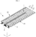
- FIG. 1 is a perspective view of a bus bar assembly according to an embodiment of the present invention
- FIG. 2 is an exploded perspective view of the bus bar assembly according to an embodiment of the present invention
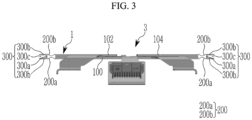
- FIG. 3 is a side view of the bus bar assembly according to the embodiment of the present invention.
- a bus bar assembly according to an embodiment is formed by fixing a bus bar to a bus bar holder.
- the bus bar assembly according to the embodiment is configured such that bus bars are arranged in a double layer, for example, in two layers.
- Such a bus bar assembly is provided to a battery module and electrically connects a plurality of rechargeable battery cells accommodated in a housing of the battery module.
- a bus bar holder 1 may include a resin material body 10 and includes a plurality of bus bar disposal area portions 100, 102, and 104 in which the bus bar 20 is disposed.
- a bus bar 20 is disposed in each of the bus bar disposal area portions 100, 102, and 104, and the number of bus bars 20 disposed in each bus bar disposal area 100, 102, and 104 may be properly adjusted according to the number of battery cells and an electrical connection relationship of the battery cells.
- openings 100a, 102a, and 104a for exposing a terminal part of the bus bar 20 are arranged along one direction (e.g., a length direction of the body, x) in each of the bus bar disposal area portions 100, 102, and 104.
- the bus bar holder 1 may be provided with three bus bar disposal area portions 100, 102, and 104.
- Each of the bus bar disposal area portions 100, 102, and 104 may have an outline of an approximate rectangle.
- the first bus bar disposal area 100 disposed in a center has a larger size than the second and third bus bar disposal area portions 102 and 104.
- the second and third bus bar disposal area portions 102 and 104 disposed in the left and right while neighboring the first bus bar disposal area portion 100 have a smaller size than the first bus bar disposal area portion 100, and are connected with the first bus bar disposal area portion 100 so as to be able to be stacked on the first bus bar disposal area portion 100.
- the size of the second bus bar disposal area portion 102 and the size of the third bus bar disposal area portion 104 may be the same.
- Hinge portions 200 are disposed between the first bus bar disposal area portion 100 and the second bus bar disposal area portion 102, and between the first bus bar disposal area portion 100 and the third bus bar disposal area portion 104, for stacking of bus bar disposal area portions 100, 102, and 104.
- the hinge portion 200 may have a thinner thickness than the bus bar disposal area portions 100, 102, and 104 to have flexibility.
- the hinge portion 200 may be formed of the same resin material as the body 10 and may be integrally formed with the bus bar disposal area portions 100, 102, and 104 through injection molding or the like.
- the hinge portion 200 may extend discontinuously along the length direction (x) of the body 10, and specifically may be disposed between the openings 100a, 102a, and 104a of the bus bar disposal area portions 100, 102, and 104 such that the first bus bar disposal area portion 100 and the second bus bar disposal area portion 102 may be connected and the first bus bar disposal area portion 100 and the third bus bar disposal area portion 104 may be connected.
- the second bus bar disposal area portion 102 and the third bus bar disposal area portion 104 in the unfolded state as shown in FIG. 2 may rotate 180 degrees toward the first bus bar disposal area portion 100 and may be stacked on the first bus bar disposal area portion 100.
- the opening 102a of the second bus bar disposal area portion 102 may overlap the opening 100a of the first bus bar disposal area portion 100
- the opening 104a of the third bus bar disposal area portion 104 may overlap the opening 100a of the first bus bar disposal area portion 100.
- a fastening portion 300 that can be used to fix the bus bar assembly to the housing of the battery module adjacent to the hinge portion 200 may be provided.
- the hinge portion 200 may be divided into a first hinge portion 200a connected to the first bus bar disposal area portion 100 and a second hinge portion 200b connected to the second and third bus bar disposal area portions 102 and 104, and the fastening portion 300 may be formed by including a connection portion 300a disposed between the first hinge portion 200a and the second hinge portion 200b and connected thereto, and a support portion 300b extending vertically from both ends of the connection portion 300a with respect to the connection portion 300a to form an insertion space 300c therebetween.
- connection portion 300a and both support portions 300b that form the fastening portion 300 may have an appropriate thickness such that they can receive force when the components of the housing of the battery module are inserted into the insertion space 300c.
- the fastening portion 300 when viewed in a state in which the second and third bus bar disposal area portions 102 and 104 are stacked on the first bus bar disposal area portion 100, the fastening portion 300 is disposed continuously along the length direction (x) of the body 10, that is, arranged opposite to each other on both edges of the first bus bar disposal area portion 100.
- both support portions 300b of the fastening portion 300 are disposed side by side in a form extending outwardly of the bus bar holder 1 such that the insertion space 300c may be maintained in an open state.
- the bus bar holder 1 that can be configured as described above may be configured as the bus bar assembly 3 by disposing the bus bar 20 to each of the plurality of bus bar disposal area portions 100, 102, and 104.
- the bus bar holder 1 and the bus bar 20 may be formed to the bus bar assembly 3 through overmolding.
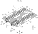
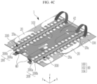
- FIG. 4A to FIG. 4E are provided for description of an assembling process of the bus bar assembly according to the embodiment of the present invention.
- the above-described bus bar holder 1 may be formed through injection molding.
- the bus bar disposal area portions 100, 102, and 104 are over-molded with the corresponding bus bar 20.
- the bus bar disposal area portions 100, 102, and 104 are over-molded with the corresponding bus bar 20.
- five bus bars 20 are disposed and over-molded in the first bus bar disposal area portion 100
- two bus bars 20 are respectively over-molded in the second bus bar disposal area portion 102 and the third bus bar disposal area portion 104.
- the second bus bar disposal area portion 102 and the third bus bar disposal area portion 104 maintain an unfolded state
- a flexible print circuit 40 may be connected to some of the bus bars 20 disposed to the first bus bar disposal area portion 100 (refer to FIG. 4A ).
- the shape of the bus bar 20 is similar such that the bus bar 20 may not be disposed at the exact position of each bus bar disposal area portion 100, 102, and 104.
- a hole 20a is formed in a terminal portion of the bus bar 20, but the position and number of the holes 20a are designed differently for each bus bar 20 with a different shape to classify the bus bar 20, thereby identifying the bus bar 20 such that each bus bar 20 may be assembled to the exact position of each of the bus bar disposal area portions 100, 102, and 104.
- the hole 20a provided in the bus bar 20 can be provided to workers as mistake-proofing to prevent misassembly.
- an insulating sheet 42 may be disposed on the first bus bar disposal area portion 100 (refer to FIG. 4B ).
- the insulating sheet 42 is for insulating between the bus bar 20 disposed in the plurality of bus bar disposal area portions 100, 102, and 104.
- the second bus bar disposal area portion 102 and the third bus bar disposal area portion 104 are folded and stacked on the first bus bar disposal area portion 100 by using the hinge portion 200 (refer to FIG. 4C ).
- the opening 102a of the second bus bar disposal area portion 102 overlaps the opening 100a of the first bus bar disposal area portion 100
- the opening 104a of the third bus bar disposal area portion 104 overlaps the opening 100a of the first bus bar disposal area portion 100.
- the second bus bar disposal area portion 102 and the third bus bar disposal area portion 104 are spaced apart at an arbitrary interval g.
- a flexible print circuit 44 for sensing is disposed between the second bus bar disposal area portion 102 and the third bus bar disposal area portion 104, and each bus bar 20 is electrically connected to the flexible printed circuit to complete the assembly of the bus bar assembly 3 (refer to FIG. 4E ).
- the assembled bus bar assembly 3 may be connected to the housing of the battery module.
- FIG. 5 shows a battery module 5 according to the embodiment of the present invention, and, as shown in FIG. 5 , the bus bar assembly 3 may be disposed on the top of the housing 52 in which a plurality of battery cell (e.g., lithium rechargeable battery cell) arrays 50 are accommodated and connected to a side plate 520 of the housing 52.
- a plurality of battery cell e.g., lithium rechargeable battery cell
- the housing 52 may be formed by a combination of a pair of end plates (not shown) and a pair of side plates 520.
- the battery module 5 is formed by connecting the bus bar assembly 3 to the pair of side plates 520.
- both fastening portions 300 of the bus bar holder 1 are positioned at the end of both sides of the housing 520.
- the ends of both side plates 520 are inserted into the insertion space 300c of both fastening portions 300.
- the insertion may be carried out by being forcibly fitted.
- the bus bar assembly 3 can be fixed to the housing 52, and the bus bar assembly 3 can also fix the battery cell array 50.
- the coupling between the fastening portion 300 and the housing 52 is not limited to the forcibly fitting method.
- the support portion 300b of the fastening portion 300 and the end of the side plate 520 may be fixed through welding.
Landscapes
- Chemical & Material Sciences (AREA)
- Chemical Kinetics & Catalysis (AREA)
- Electrochemistry (AREA)
- General Chemical & Material Sciences (AREA)
- Connection Of Batteries Or Terminals (AREA)
- Battery Mounting, Suspending (AREA)
Applications Claiming Priority (1)
| Application Number | Priority Date | Filing Date | Title |
|---|---|---|---|
| KR1020210193102A KR20230102738A (ko) | 2021-12-30 | 2021-12-30 | 버스 바 홀더, 버스 바 조립체 및 전지 모듈 |
Publications (2)
| Publication Number | Publication Date |
|---|---|
| EP4207448A2 true EP4207448A2 (de) | 2023-07-05 |
| EP4207448A3 EP4207448A3 (de) | 2023-08-02 |
Family
ID=84569233
Family Applications (1)
| Application Number | Title | Priority Date | Filing Date |
|---|---|---|---|
| EP22216208.3A Pending EP4207448A3 (de) | 2021-12-30 | 2022-12-22 | Sammelschienenhalter, sammelschienenanordnung und batteriemodul |
Country Status (4)
| Country | Link |
|---|---|
| US (1) | US20230216150A1 (de) |
| EP (1) | EP4207448A3 (de) |
| KR (1) | KR20230102738A (de) |
| CN (1) | CN116387762A (de) |
Families Citing this family (3)
| Publication number | Priority date | Publication date | Assignee | Title |
|---|---|---|---|---|
| WO2025124753A1 (de) * | 2023-12-12 | 2025-06-19 | Diehl Advanced Mobility GmbH | Zellkontaktierungssystem |
| KR20250109044A (ko) * | 2024-01-09 | 2025-07-16 | 주식회사 엘지에너지솔루션 | 배터리 모듈 조립 장치 |
| EP4601089A1 (de) * | 2024-02-06 | 2025-08-13 | LG Energy Solution, Ltd. | Batteriezellenanordnung, batteriepack und transportvorrichtung damit |
Family Cites Families (4)
| Publication number | Priority date | Publication date | Assignee | Title |
|---|---|---|---|---|
| JP5524697B2 (ja) * | 2010-04-22 | 2014-06-18 | 矢崎総業株式会社 | バッテリ接続プレート |
| JP5733061B2 (ja) * | 2011-07-05 | 2015-06-10 | 株式会社オートネットワーク技術研究所 | 電池配線モジュール |
| JP7184606B2 (ja) * | 2018-11-20 | 2022-12-06 | 日本メクトロン株式会社 | 支持部材及びバッテリモジュール |
| KR102392788B1 (ko) * | 2019-01-08 | 2022-04-28 | 주식회사 엘지에너지솔루션 | 폴더블 사이드 플레이트를 구비하는 배터리 모듈 및 그 제조 방법 |
-
2021
- 2021-12-30 KR KR1020210193102A patent/KR20230102738A/ko active Pending
-
2022
- 2022-12-22 EP EP22216208.3A patent/EP4207448A3/de active Pending
- 2022-12-22 US US18/145,623 patent/US20230216150A1/en active Pending
- 2022-12-23 CN CN202211666701.XA patent/CN116387762A/zh active Pending
Also Published As
| Publication number | Publication date |
|---|---|
| US20230216150A1 (en) | 2023-07-06 |
| KR20230102738A (ko) | 2023-07-07 |
| CN116387762A (zh) | 2023-07-04 |
| EP4207448A3 (de) | 2023-08-02 |
Similar Documents
| Publication | Publication Date | Title |
|---|---|---|
| EP3817090B1 (de) | Batteriemodul | |
| EP4207448A2 (de) | Sammelschienenhalter, sammelschienenanordnung und batteriemodul | |
| JP6496455B2 (ja) | バッテリーモジュール及びこれを含むバッテリーパック | |
| EP1839349B1 (de) | Messleiterplattenbaugruppe für ein sekundärbatteriemodul | |
| KR102722638B1 (ko) | 전지 모듈 및 그 제조 방법 | |
| US8535820B2 (en) | Battery module | |
| EP4053989B1 (de) | Batteriemodul mit stromschiene, batteriepack und fahrzeug | |
| CN114730931B (zh) | 电极引线与电压感测构件之间的连接简化的电池模块及包括其的电池组 | |
| KR102444124B1 (ko) | 배터리 모듈 및 이를 포함하는 배터리 팩 | |
| EP3561902B1 (de) | Batteriemodul, batteriepack mit dem batteriemodul und fahrzeug mit dem batteriepack | |
| US20230395946A1 (en) | Battery module and manufacturing method of the same | |
| EP4002570A1 (de) | Batteriemodul und dieses umfassendes batteriepack | |
| CN114730930B (zh) | 电极引线与电压感测构件之间的连接简化的电池模块及包括其的电池组 | |
| KR20220120512A (ko) | 전지 모듈 및 이의 제조 방법 | |
| EP4087014A1 (de) | Batteriemodul, batteriesatz damit und verfahren zu seiner herstellung | |
| KR20160123788A (ko) | 전지 팩 | |
| KR102543155B1 (ko) | 버스바 프레임 및 이를 갖는 배터리 모듈 | |
| EP2830121B1 (de) | Wiederaufladbare Batterie | |
| EP4089792A1 (de) | Batteriemodul, batteriesatz damit und herstellungsverfahren dafür | |
| EP3916838A1 (de) | Sammelschienenmodul und herstellungsverfahren dafür | |
| EP3817089B1 (de) | Batteriemodul | |
| EP4576404A1 (de) | Batteriepack | |
| EP4614666A2 (de) | Sekundärbatterie | |
| JP2023511215A (ja) | バッテリーモジュール、それを含むバッテリーパック及び自動車 | |
| KR102523946B1 (ko) | 버스바 프레임 및 이를 갖는 배터리 모듈 |
Legal Events
| Date | Code | Title | Description |
|---|---|---|---|
| PUAI | Public reference made under article 153(3) epc to a published international application that has entered the european phase |
Free format text: ORIGINAL CODE: 0009012 |
|
| STAA | Information on the status of an ep patent application or granted ep patent |
Free format text: STATUS: REQUEST FOR EXAMINATION WAS MADE |
|
| PUAL | Search report despatched |
Free format text: ORIGINAL CODE: 0009013 |
|
| 17P | Request for examination filed |
Effective date: 20221222 |
|
| AK | Designated contracting states |
Kind code of ref document: A2 Designated state(s): AL AT BE BG CH CY CZ DE DK EE ES FI FR GB GR HR HU IE IS IT LI LT LU LV MC ME MK MT NL NO PL PT RO RS SE SI SK SM TR |
|
| AK | Designated contracting states |
Kind code of ref document: A3 Designated state(s): AL AT BE BG CH CY CZ DE DK EE ES FI FR GB GR HR HU IE IS IT LI LT LU LV MC ME MK MT NL NO PL PT RO RS SE SI SK SM TR |
|
| RIC1 | Information provided on ipc code assigned before grant |
Ipc: H01M 50/507 20210101ALI20230626BHEP Ipc: H01M 50/204 20210101AFI20230626BHEP |