EP4207453A1 - Instrument électronique - Google Patents
Instrument électronique Download PDFInfo
- Publication number
- EP4207453A1 EP4207453A1 EP21861206.7A EP21861206A EP4207453A1 EP 4207453 A1 EP4207453 A1 EP 4207453A1 EP 21861206 A EP21861206 A EP 21861206A EP 4207453 A1 EP4207453 A1 EP 4207453A1
- Authority
- EP
- European Patent Office
- Prior art keywords
- battery
- positive terminal
- load side
- terminal
- negative terminal
- Prior art date
- Legal status (The legal status is an assumption and is not a legal conclusion. Google has not performed a legal analysis and makes no representation as to the accuracy of the status listed.)
- Pending
Links
Images




Classifications
-
- H—ELECTRICITY
- H01—ELECTRIC ELEMENTS
- H01M—PROCESSES OR MEANS, e.g. BATTERIES, FOR THE DIRECT CONVERSION OF CHEMICAL ENERGY INTO ELECTRICAL ENERGY
- H01M50/00—Constructional details or processes of manufacture of the non-active parts of electrochemical cells other than fuel cells, e.g. hybrid cells
- H01M50/50—Current conducting connections for cells or batteries
- H01M50/572—Means for preventing undesired use or discharge
- H01M50/574—Devices or arrangements for the interruption of current
-
- G—PHYSICS
- G01—MEASURING; TESTING
- G01L—MEASURING FORCE, STRESS, TORQUE, WORK, MECHANICAL POWER, MECHANICAL EFFICIENCY, OR FLUID PRESSURE
- G01L19/00—Details of, or accessories for, apparatus for measuring steady or quasi-steady pressure of a fluent medium insofar as such details or accessories are not special to particular types of pressure gauges
- G01L19/0061—Electrical connection means
- G01L19/0084—Electrical connection means to the outside of the housing
-
- H—ELECTRICITY
- H01—ELECTRIC ELEMENTS
- H01M—PROCESSES OR MEANS, e.g. BATTERIES, FOR THE DIRECT CONVERSION OF CHEMICAL ENERGY INTO ELECTRICAL ENERGY
- H01M50/00—Constructional details or processes of manufacture of the non-active parts of electrochemical cells other than fuel cells, e.g. hybrid cells
- H01M50/20—Mountings; Secondary casings or frames; Racks, modules or packs; Suspension devices; Shock absorbers; Transport or carrying devices; Holders
- H01M50/202—Casings or frames around the primary casing of a single cell or a single battery
-
- H—ELECTRICITY
- H01—ELECTRIC ELEMENTS
- H01M—PROCESSES OR MEANS, e.g. BATTERIES, FOR THE DIRECT CONVERSION OF CHEMICAL ENERGY INTO ELECTRICAL ENERGY
- H01M50/00—Constructional details or processes of manufacture of the non-active parts of electrochemical cells other than fuel cells, e.g. hybrid cells
- H01M50/20—Mountings; Secondary casings or frames; Racks, modules or packs; Suspension devices; Shock absorbers; Transport or carrying devices; Holders
- H01M50/204—Racks, modules or packs for multiple batteries or multiple cells
- H01M50/207—Racks, modules or packs for multiple batteries or multiple cells characterised by their shape
- H01M50/209—Racks, modules or packs for multiple batteries or multiple cells characterised by their shape adapted for prismatic or rectangular cells
-
- H—ELECTRICITY
- H01—ELECTRIC ELEMENTS
- H01M—PROCESSES OR MEANS, e.g. BATTERIES, FOR THE DIRECT CONVERSION OF CHEMICAL ENERGY INTO ELECTRICAL ENERGY
- H01M50/00—Constructional details or processes of manufacture of the non-active parts of electrochemical cells other than fuel cells, e.g. hybrid cells
- H01M50/20—Mountings; Secondary casings or frames; Racks, modules or packs; Suspension devices; Shock absorbers; Transport or carrying devices; Holders
- H01M50/244—Secondary casings; Racks; Suspension devices; Carrying devices; Holders characterised by their mounting method
-
- H—ELECTRICITY
- H01—ELECTRIC ELEMENTS
- H01M—PROCESSES OR MEANS, e.g. BATTERIES, FOR THE DIRECT CONVERSION OF CHEMICAL ENERGY INTO ELECTRICAL ENERGY
- H01M50/00—Constructional details or processes of manufacture of the non-active parts of electrochemical cells other than fuel cells, e.g. hybrid cells
- H01M50/20—Mountings; Secondary casings or frames; Racks, modules or packs; Suspension devices; Shock absorbers; Transport or carrying devices; Holders
- H01M50/247—Mountings; Secondary casings or frames; Racks, modules or packs; Suspension devices; Shock absorbers; Transport or carrying devices; Holders specially adapted for portable devices, e.g. mobile phones, computers, hand tools or pacemakers
-
- H—ELECTRICITY
- H01—ELECTRIC ELEMENTS
- H01M—PROCESSES OR MEANS, e.g. BATTERIES, FOR THE DIRECT CONVERSION OF CHEMICAL ENERGY INTO ELECTRICAL ENERGY
- H01M50/00—Constructional details or processes of manufacture of the non-active parts of electrochemical cells other than fuel cells, e.g. hybrid cells
- H01M50/20—Mountings; Secondary casings or frames; Racks, modules or packs; Suspension devices; Shock absorbers; Transport or carrying devices; Holders
- H01M50/296—Mountings; Secondary casings or frames; Racks, modules or packs; Suspension devices; Shock absorbers; Transport or carrying devices; Holders characterised by terminals of battery packs
-
- H—ELECTRICITY
- H02—GENERATION; CONVERSION OR DISTRIBUTION OF ELECTRIC POWER
- H02J—ELECTRIC POWER NETWORKS; CIRCUIT ARRANGEMENTS OR SYSTEMS FOR SUPPLYING OR DISTRIBUTING ELECTRIC POWER; SYSTEMS FOR STORING ELECTRIC ENERGY
- H02J7/00—Circuit arrangements for charging or discharging batteries or for supplying loads from batteries
- H02J7/60—Circuit arrangements for charging or discharging batteries or for supplying loads from batteries including safety or protection arrangements
-
- H—ELECTRICITY
- H02—GENERATION; CONVERSION OR DISTRIBUTION OF ELECTRIC POWER
- H02J—ELECTRIC POWER NETWORKS; CIRCUIT ARRANGEMENTS OR SYSTEMS FOR SUPPLYING OR DISTRIBUTING ELECTRIC POWER; SYSTEMS FOR STORING ELECTRIC ENERGY
- H02J7/00—Circuit arrangements for charging or discharging batteries or for supplying loads from batteries
- H02J7/60—Circuit arrangements for charging or discharging batteries or for supplying loads from batteries including safety or protection arrangements
- H02J7/685—Circuit arrangements for charging or discharging batteries or for supplying loads from batteries including safety or protection arrangements using connection detecting circuits
-
- H—ELECTRICITY
- H02—GENERATION; CONVERSION OR DISTRIBUTION OF ELECTRIC POWER
- H02J—ELECTRIC POWER NETWORKS; CIRCUIT ARRANGEMENTS OR SYSTEMS FOR SUPPLYING OR DISTRIBUTING ELECTRIC POWER; SYSTEMS FOR STORING ELECTRIC ENERGY
- H02J7/00—Circuit arrangements for charging or discharging batteries or for supplying loads from batteries
- H02J7/70—Circuit arrangements for charging or discharging batteries or for supplying loads from batteries characterised by the mechanical construction
-
- H—ELECTRICITY
- H02—GENERATION; CONVERSION OR DISTRIBUTION OF ELECTRIC POWER
- H02J—ELECTRIC POWER NETWORKS; CIRCUIT ARRANGEMENTS OR SYSTEMS FOR SUPPLYING OR DISTRIBUTING ELECTRIC POWER; SYSTEMS FOR STORING ELECTRIC ENERGY
- H02J7/00—Circuit arrangements for charging or discharging batteries or for supplying loads from batteries
- H02J7/70—Circuit arrangements for charging or discharging batteries or for supplying loads from batteries characterised by the mechanical construction
- H02J7/751—Circuit arrangements for charging or discharging batteries or for supplying loads from batteries characterised by the mechanical construction concerning the insertion or the connection of the batteries
-
- H—ELECTRICITY
- H01—ELECTRIC ELEMENTS
- H01M—PROCESSES OR MEANS, e.g. BATTERIES, FOR THE DIRECT CONVERSION OF CHEMICAL ENERGY INTO ELECTRICAL ENERGY
- H01M2220/00—Batteries for particular applications
- H01M2220/30—Batteries in portable systems, e.g. mobile phone, laptop
-
- H—ELECTRICITY
- H02—GENERATION; CONVERSION OR DISTRIBUTION OF ELECTRIC POWER
- H02J—ELECTRIC POWER NETWORKS; CIRCUIT ARRANGEMENTS OR SYSTEMS FOR SUPPLYING OR DISTRIBUTING ELECTRIC POWER; SYSTEMS FOR STORING ELECTRIC ENERGY
- H02J2105/00—Networks for supplying or distributing electric power characterised by their spatial reach or by the load
- H02J2105/40—Networks for supplying or distributing electric power characterised by their spatial reach or by the load characterised by the loads connecting to the networks or being supplied by the networks
- H02J2105/44—Portable electronic devices
-
- Y—GENERAL TAGGING OF NEW TECHNOLOGICAL DEVELOPMENTS; GENERAL TAGGING OF CROSS-SECTIONAL TECHNOLOGIES SPANNING OVER SEVERAL SECTIONS OF THE IPC; TECHNICAL SUBJECTS COVERED BY FORMER USPC CROSS-REFERENCE ART COLLECTIONS [XRACs] AND DIGESTS
- Y02—TECHNOLOGIES OR APPLICATIONS FOR MITIGATION OR ADAPTATION AGAINST CLIMATE CHANGE
- Y02E—REDUCTION OF GREENHOUSE GAS [GHG] EMISSIONS, RELATED TO ENERGY GENERATION, TRANSMISSION OR DISTRIBUTION
- Y02E60/00—Enabling technologies; Technologies with a potential or indirect contribution to GHG emissions mitigation
- Y02E60/10—Energy storage using batteries
Definitions
- the present invention relates to a battery-powered electronic device.
- a battery-powered electronic device requires no connection to an external power source, so that it can be used anywhere.
- a sensor device described in Patent Citation 1 is an electronic device that senses the state of a manufacturing device installed on a manufacturing line, and includes a button cell as a power source. Further, a battery holder for holding the button cell can be inserted into a slit-shaped insertion portion of a housing to supply the sensor device with power.
- the battery holder is configured such that a first terminal and a second terminal that are brought into contact with a positive electrode and a negative electrode of the button cell, respectively, a processing circuit processing the output of a sensor element, a communication circuit communicating with the outside, and a connector configured to be electrically connected to the sensor element, or the like are mounted on a support substrate.
- the button cell is mounted in the battery holder, so that the first terminal and the second terminal on the load side to which the processing circuit, the communication circuit, etc. are connected are electrically connected to the positive electrode and the negative electrode of the button cell.
- Patent Citation 1 JP 2019-153485 A (Pages 8 and 9, FIG. 6 )
- the positive electrode of the button cell when the button cell is attached to and detached from the battery holder, the positive electrode of the button cell may be connected to the positive terminal with the reference potential on the ground side, which is the reference of the circuit operation, being not determined. Accordingly, the voltage may become unstable due to the residual charge in the processing circuit, the communication circuit, or the like provided on the load side, to impose a negative effect such as malfunction or damage of the circuit.
- the present invention has been made in view of such problems, and an object of the present invention is to provide an electronic device that enables stable circuit operation.
- an electronic device including a load and configured for energizing the load in accordance with attachment and detachment of a battery to and from the electronic device, wherein, the electronic device further includes a positive terminal and a negative terminal on a load side, in a process of the attachment and the detachment of the battery, the positive terminal on the load side and a positive terminal of the battery are electrically connected to and disconnected from each other in a state in which the negative terminal on the load side is electrically connected to a negative terminal of the battery.
- the negative terminal on the load side is first electrically connected to the negative terminal of the battery, so that the positive terminal on the load side and the positive terminal of the battery can be electrically connected to each other with the reference potential of the circuit being determined, to set the circuit as a target potential difference.
- the electrical connection between the negative terminal on the load side and the negative terminal of the battery is maintained, and the positive terminal on the load side and the positive terminal of the battery can be first electrically disconnected to each other with the reference potential of the circuit being determined. Accordingly, in the process of attachment and detachment of the battery, the circuit can be reliably set to the target potential difference to enable the stable circuit operation.
- the electronic device further includes a switch that switches between an electrical connection and an electrical disconnection of the positive terminal on the load side and the positive terminal of the battery according to an operation of the attachment and the detachment of the battery.
- a switch that switches between an electrical connection and an electrical disconnection of the positive terminal on the load side and the positive terminal of the battery according to an operation of the attachment and the detachment of the battery.
- the switch is provided on a member on the load side. According to this preferable configuration, since the switch is configured on the member on the load side, a specially shaped battery is not required to be used, and various types of batteries can be used.
- the positive terminal and the negative terminal on the load side are arranged side by side, and the switch is a return switch that projects in an extending direction of the positive terminal and the negative terminal on the load side so as to be returnable.
- the switch when the battery is attached, the switch is pressed and retracted to electrically connect the positive terminal on the load side and the positive terminal of the battery with the positive terminal and the negative terminal of the battery being in contact with the positive terminal and the negative terminal on the load side.
- the switch when the battery is detached, the switch returns in the extending direction of the positive terminal and the negative terminal on the load side to electrically disconnect the positive terminal on the load side and the positive terminal of the battery with the contact between the positive terminal and the negative terminal of the battery and the positive terminal and the negative terminal on the load side being maintained.
- the positive terminal and the negative terminal on the load side are be returnable in the extending direction.
- the switch is pressed and retracted to electrically connect the positive terminal on the load side and the positive terminal of the battery in the process of the positive terminal and the negative terminal on the load side being retracted due to the contact between the positive terminal and the negative terminal of the battery and the positive terminal and the negative terminal on the load side.
- the switch when the battery is detached, the switch returns in the extending direction of the positive terminal and the negative terminal on the load side to electrically disconnect the positive terminal on the load side and the positive terminal of the battery with the positive terminal and the negative terminal of the battery being pressed against the positive terminal and the negative terminal on the load side with the restoring force to ensure that the contact therebetween is maintained.
- the electronic device further includes a battery holder that holds the battery, and the battery holder is provided with a projection configured for pressing the switch.
- the switch is pressed by the projection of the battery holder according to the operation of attaching and detaching the battery, so that the operation timing of the switch can be adjusted according to the projection amount of the projection.
- the electronic device further includes a positioning mechanism configured for positioning the battery holder.
- the battery holder can be positioned to reliably press the switch with the projection of the battery holder, and the movement of the battery holder can be restricted to reliably hold the state of the switch being pressed by the projection.
- the battery used in the electronic device according to the present invention may be a battery which can be attached to and detached from the body of the electronic device, or be a battery held by a battery holder which can be attached to and detached from the body of the electronic device.
- the positive electrode and the negative electrode of the battery may be directly electrically connected to a circuit on the load side, or may be indirectly electrically connected to the circuit via terminals provided in the battery holder.
- FIGS. 1 to 9 An electronic device according to a first embodiment of the present invention will be described with reference to FIGS. 1 to 9 .
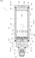
- the left and right sides when viewed from the front side of FIG. 3 will be described as the left and right sides of the electronic device.
- the left side of the drawing on which a sensor unit 30 is provided will be described as the left side of the electronic device
- the right side of the drawing on which a cap member 23 is attached will be described as the right side of the electronic device.
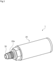
- the electronic device is a pressure sensor 1 configured to detect the pressure of an object to be measured and including a battery 10 (see FIG. 2 ) as a power source.
- the pressure sensor 1 is fixed to an installed portion such as a pipe, a duct, or a tank (not illustrated), and detects the pressure of the object to be measured inside the installed portion.
- the object to be measured is a fluid such as a liquid or a gas.
- the pressure sensor 1 mainly includes a housing 20, the sensor unit 30, a battery holder 100 (see FIG. 2 ), and a circuit unit 40 (see FIG. 3 ).
- the sensor unit 30 is attached to the left end portion of the housing 20.
- the battery holder 100 is placed in the housing 20 and holds the battery 10.
- a load according to the present invention is composed of the sensor unit 30 and the circuit unit 40.
- a screw portion 20a of the housing 20 is screwed into a mounting port of a pipe (not illustrated) to fix and use the pressure sensor 1.
- the screw portion 20a is formed at the left end portion of the outer periphery of the housing 20.
- a sensor element (not illustrated) provided in the sensor unit 30 outputs a voltage corresponding to the pressure applied from the object to be measured, the fluid, inside the pipe.
- a processing chip 31 converts this voltage into a pressure signal.
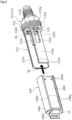
- the housing 20 includes a mounting member 21, an outer case 121, and an inner case 122 (see FIGS. 4 and 5 ).
- the screw portion 20a (see FIG. 1 ) is formed at the left end portion of the mounting member 21.
- the outer case 121 includes a cover member 22 attached to the right end portion of the mounting member 21 and the cap member 23 closing an opening 22a on the right side of the cover member 22.
- the inner case 122 is fixed to the mounting member 21 and is covered with the cover member 22 and the cap member 23, namely, the outer case 121.
- the mounting member 21 includes a tubular base portion 21a, a small diameter portion 21b extending to the left from the base portion 21a, a flange portion 21c projecting radially outward from the right end portion of the outer periphery of the base portion 21a, and a large diameter portion 21d extending to the right from the base portion 21a.
- the small diameter portion 21b has the screw portion 20a (see FIG. 1 ) described above formed on the outer periphery.
- the small diameter portion 21b also has an annular recess 21e formed at the right end portion of the outer periphery, and an O-ring 24 is mounted on the recess 21e.
- the screw portion 20a formed on the outer periphery of the small diameter portion 21b is screwed into the mounting port of the pipe (not illustrated) to compress the O-ring 24 between the pipe and the mounting member 21 to ensure the sealing performance.
- a recess 21f is formed at the left end portion of the small diameter portion 21b, the recess 21f being recessed to the right, and the sensor unit 30 is inserted and fitted into the recess 21f from the left to be fixed by welding. Although details are omitted, the sealing performance is ensured so that the object to be measured, the fluid, would not enter the side of a through hole 21m on which the processing chip 31 is arranged.
- the large diameter portion 21d has a screw portion 21g (see FIGS. 4 and 5 ) formed on the outer periphery.
- the large diameter portion 21d also has an annular recess 21h formed at the left end portion of the outer periphery, and an O-ring 25 is mounted on the recess 21h.
- a screw portion (not illustrated) formed on the inner periphery of the left end portion of the cover member 22 is screwed into the screw portion 21g formed on the outer periphery of the large diameter portion 21d to compress the O-ring 25 between the mounting member 21 and the cover member 22 to ensure the sealing performance.
- a stepped recess 21k is formed at the right end portion of the large diameter portion 21d, the stepped recess 21k being recessed to the left, and a part of the circuit unit 40 is placed in the recess 21k.
- the recess 21f formed in the small diameter portion 21b and the recess 21k formed in the large diameter portion 21d are communicated with each other through the through hole 21m extending through the base portion 21a in the left-right direction.
- the sensor unit 30 and the circuit unit 40 are electrically connected to each other by a flexible printed wiring board (not illustrated) extending in the through hole 21m.
- the cover member 22 constituting the outer case 121 forms a cylindrical shape, and the left end portion thereof is screwed into the screw portion 21g (see FIGS. 4 and 5 ) formed on the outer periphery of the large diameter portion 21d of the mounting member 21 to attach the cover member 22. Further, a screw portion 23c of the cap member 23 also constituting the outer case 121 is screwed into the right end portion of the cover member 22 to close the opening 22a.
- the cap member 23 includes a disk-shaped base portion 23a and a small diameter portion 23b projecting to the left from the left side surface of the base portion 23a.
- the small diameter portion 23b has the screw portion 23c (see FIG. 2 ) formed on the outer periphery.
- the small diameter portion 23b also has an annular recess 23d formed at the right end portion of the outer periphery, and an O-ring 26 is mounted on the recess 23d.
- the screw portion 23c of the cap member 23 is screwed into a screw portion (not illustrated) formed on the inner periphery of the right end portion of the cover member 22 to compress the O-ring 26 between the cover member 22 and the cap member 23 to ensure the sealing performance. Accordingly, the internal space of the outer case 121 is defined to be substantially sealed, in which the circuit unit 40 and the battery holder 100 are placed.
- a recess 23e is formed at the left end portion of the small diameter portion 23b, the recess 23e being recessed to the right, and a handle 100d is placed in the recess 23e, the handle 100d being formed at the right end portion of the battery holder 100.
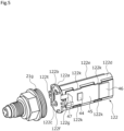
- the inner case 122 is made of a resin material and includes the base portion 122a, and a first plate portion 122d and a second plate portion 122e that extend from the base portion 122a in a direction in which the cap member 23 is arranged, namely, to the right (to the left in FIG. 4 ).
- the base portion 122a of the inner case 122 is fixed to the mounting member 21 by screws 123 (see FIG. 4 ).
- the base portion 122a has through holes 122b, 122c formed side by side as described above. Further, the base portion 122a has a substantially triangular through hole 122t into and from which a wall portion 100b of the battery holder 100, which will be described later, can be inserted and removed.
- a plurality of protrusions 122f is formed on the radially outer side of the left surface of the base portion 122a, the protrusions 122f projecting to the left.
- the radially outer portion of a circuit board 41 constituting the circuit unit 40 is held in the left-right direction between the tips of these protrusions 122f and the stepped portion formed in the recess 21k of the mounting member 21 when the inner case 122 is fixed to the mounting member 21. Accordingly, the circuit board 41 can be securely supported between the inner case 122 and the mounting member 21 (see FIG. 3 ).
- bosses 122g is provided in the base portion 122a, the bosses 122g having through holes through which the screws 123 extend (See FIGS.4 and 5 ).
- the inner surface of the first plate portion 122d is curved along the surface shape of the battery 10 held by the battery holder 100. Further, a rectangular protrusion 122h is formed in the left end portion (the right end portion in FIG. 4 ) of the inner surface of the first plate portion 122d, and can be fitted into a recess 10c (see FIGS. 2 and 3 ) formed on the surface of the battery 10. Accordingly, a direction in which the battery holder 100 is inserted into and removed from the inner case 122 can be restricted to prevent the reverse connection of the battery 10.
- the outer surface of the first plate portion 122d forms a flat surface at the substantially vertically central portions, and a pair of upper and lower hook-shaped projections 122k is provided at the upper and lower end portions of the first plate portion 122d at each of two locations in the left-right direction, and can hold the circuit board 45 constituting the circuit unit 40.
- the circuit board 45 is inserted between the upper and lower projections 122k from the right side of the first plate portion 122d.
- the upper and lower side surfaces of the first plate portion 122d are curved along the inner periphery of the cover member 22 constituting the outer case 121.
- the second plate portion 122e is formed to have a smaller dimension in the vertical direction, namely, in the lateral direction than the first plate portion 122d.
- a pair of protruded portions 122m is formed on the inner surface side of the upper and lower end portions of the second plate portion 122e to extend in the left-right direction, namely, the longitudinal direction, which is the direction of insertion and removal of the battery holder 100.
- the protruded portions 122m each form a semicircular shape in cross section.
- a pair of upper and lower hemispherical protrusions 122n is formed at the left end portion (the right end portion in FIG. 4 ) on the inner surface of the second plate portion 122e.
- a substantially rectangular cutout 122s is formed at a substantially vertically central portion of the right end portion (the left end portion in FIG. 4 ) of the second plate portion 122e.
- the cutout 122s is formed in the second plate portion 122e to prevent a tool such as a driver from interfering with the second plate portion 122e. This facilitates the tightening of the screws 123 into the through holes of the bosses 122g formed in the base portion 122a.
- the battery holder 100 will be described.
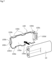
- the pack lithium battery 10 (hereinafter, simply referred to as "battery 10") that includes a positive electrode 10a and a negative electrode 10b arranged side by side on one end side of the battery holder 100 in the longitudinal direction will be described.
- the positive terminal and the negative terminal on the side of the battery 10 are the positive electrode 10a and the negative electrode 10b of the battery 10.
- the battery holder 100 mainly includes a base portion 100a, wall portions 100b, 100c, and a handle 100d.
- the base portion 100a has an inner surface curved along the surface shape of the battery 10.
- the wall portion 100b is formed into a substantially triangular shape standing from the left end portion of the base portion 100a toward the inner surface side.
- the wall portion 100c is formed into a rectangular shape standing from the right end portion of the base portion 100a toward the inner surface side.
- the handle 100d bends from the wall portion 100c and extends to the right.
- the wall portion 100b forms a substantially triangular shape, and is in contact with one end of the battery 10 in the longitudinal direction at the inner surface with the battery 10 held by the battery holder 100. Accordingly, the positive electrode 10a and the negative electrode 10b of the battery 10 are exposed from cutout spaces 100k, 100m (see FIG. 7 ) of the battery holder 100.
- the wall portion 100b may be formed into any shape as long as a positive terminal 42 and a negative terminal 43 can extend through the wall portion 100b and the wall portion 100b can expose the positive electrode 10a and the negative electrode 10b of the battery 10 so that they can be in contact with the electrical contacts of the positive terminal 42 and the negative terminal 43, respectively, and instead of the cutout shape, a through hole may be formed in the wall portion.
- the wall portion 100b is formed so as to overhang on the left side of the left end of the base portion 100a, and is provided with a projection 100n provided at a substantially central portion of the outer surface thereof and projecting to the left (see FIG. 7 ).
- a pair of upper and lower paired claws 100e is provided at each of three locations in the left-right direction at the upper and lower end portions of the base portion 100a and can hold the battery 10.
- the base portion 100a has an outer surface forming a flat surface at substantially vertically central portion, and has an insertion recess 100f.
- the insertion recess 100f is open to the left side (the right side in FIG. 4 ) on which the wall portion 100b is formed, so that the second plate portion 122e of the inner case 122 can be inserted from the right side (the left side in FIG. 4 ) into the insertion recess 100f.
- a pair of recessed grooves 100g is formed on the inner surface side of the upper and lower inner walls of the insertion recess 100f, the grooves 100g extending in the left-right direction, namely, in the longitudinal direction, that is the direction of insertion and removal of the battery holder 100, and facing each other in the vertical direction, namely, in the lateral direction.
- the recessed grooves 100g each forms a semicircular shape in cross section, and constitute a pair of guide portions G that guides the movement of the battery holder 100 in a direction of insertion and removal together with the pair of protruded portions 122m formed on the inner case 122 described above.
- the bottom surface of the insertion recess 100f has a pair of upper and lower hemispherical recesses 100h formed at the left end portion (the right end portion in FIG. 4 ).
- the pair of protrusions 122n formed on the inner case 122 described above can be recess-protrusion fitted into the recesses 100h to constitute positioning mechanisms P for the battery holder 100 and to lock the battery holder 100 so that it would not move in the left-right direction accidentally.
- the wall portion 100b of the battery holder 100 extends through the through hole 122t of the inner case 122 with the protrusions 122n of the inner case 122 recess-protrusion fitted into the recesses 100h (see FIG. 3 ).
- the circuit unit 40 mainly includes the disk-shaped circuit board 41, the positive terminal 42 and the negative terminal 43, and a rectangular plate-shaped circuit board 45 on which a processing chip 44 and a wireless chip 46 are mounted (see FIG. 5 ).
- the circuit board 41 is placed in the recess 21k of the large diameter portion 21d in the mounting member 21.
- the positive terminal 42 and the negative terminal 43 are arranged side by side so as to extend through the circuit board 41 in the thickness direction.
- the circuit board 45 is held on the outer surface of the first plate portion 122d of the inner case 122, which will be described later.
- the processing chip 44 adjusts the electric power supplied from the battery 10, processes the signal input from the sensor unit 30, and the like.
- the wireless chip 46 is provided on the circuit board 45 and performs communication with the outside.
- the circuit board 41 and the circuit board 45 are electrically connected to each other by a flexible flat cable 47. Further, the positive terminal 42 and the negative terminal 43 may not extend through the circuit board 41 in the thickness direction.
- the positive terminal 42 and the negative terminal 43 are so-called probe pins, and constitute a positive terminal and a negative terminal on the load side.
- the positive terminal 42 and the negative terminal 43 have a plunger structure, and are fixed by being inserted into and soldered to a pair of attachment holes extending through the circuit board 41 in the left-right direction, respectively.
- the positive terminal 42 and the negative terminal 43 have electrical contacts formed at the right ends and being extendable in an axial direction. When the battery holder 100 is attached, the electrical contacts are pressed and are retracted in the axial direction (see FIG. 8 ). When the battery holder 100 is detached, the electrical contacts are elastically restored and extend in the axial direction (see FIG. 9 ).
- the shape of the tips of the positive terminal 42 and the negative terminal 43 on which the electrical contacts are formed forms a planar shape, so that the area of contact with the positive electrode 10a and the negative electrode 10b of the battery 10 can be increased to distribute the stress. Accordingly, surface damage to the electrical contacts of the positive terminal 42 and the negative terminal 43 on the load side due to rattling of the battery 10 or the like is prevented.
- the positive terminal 42 and the negative terminal 43 extend through two through holes 122b, 122c that are formed side by side to extend through a base portion 122a of the inner case 122 in the thickness direction, and are supported to be retractable to the left with respective electrical contacts projecting from the through holes 122b, 122c.
- the positive terminal 42 and the negative terminal 43 are slightly retracted to the left with the battery holder 100 attached. That is, the electrical contacts of the positive terminal 42 and the negative terminal 43 are in elastic pressure contact with the positive electrode 10a and the negative electrode 10b of the battery 10 held by the battery holder 100, respectively.
- a switch 48 is provided between the positive terminal 42 and the negative terminal 43 and is fixed to a substantially central portion on the right surface of the circuit board 41.
- the switch 48 is a return switch that projects so as to be returnable in the extending direction of the electrical contacts of the positive terminal 42 and the negative terminal 43, that is, in the right direction by urging means (not illustrated) placed therein.
- the switch 48 is configured as a so-called momentary switch that connects the circuit only when pressed.
- the amount of projection of the switch 48 to the right is configured to be smaller than the amount of projection of the positive terminal 42 and the negative terminal 43 to the right.
- the circuit unit 40 can be energized to supply power from the battery 10 to the sensor unit 30. Further, the circuit unit 40 receives an input of a pressure signal from the sensor unit 30, so that signal-processing can be performed by the processing chip 44 and the communication with the outside can be performed by the wireless chip 46.
- the positive electrode 10a and the negative electrode 10b of the battery 10 are in contact with the electrical contacts of the positive terminal 42 and the negative terminal 43 on the load side, respectively, but the positive electrode 10a of the battery 10 and the positive terminal 42 on the load side are electrically disconnected to each other due to the switch 48 being turned off.
- the negative electrode 10b of the battery 10 and the negative terminal 43 on the load side are electrically connected to each other.
- the negative terminal 43 on the load side is electrically connected to the negative electrode 10b of the battery 10 before the positive terminal 42 on the load side, so that the positive electrode 10a of the battery 10 and the positive terminal 42 on the load side can be electrically connected to each other with the reference potential of the circuit being determined, to set the circuit to the target potential difference.
- the projection 100n of the battery holder 100 is separated from the switch 48 in the right direction with the positive terminal 42 and the negative terminal 43 on the load side being pressed against the positive electrode 10a and the negative electrode 10b of the battery 10 (see FIG. 9B ). That is, the switch 48 is turned off, so that the positive electrode 10a of the battery 10 and the positive terminal 42 on the load side are electrically disconnected to each other with the positive electrode 10a and the negative electrode 10b of the battery 10 being in contact with the respective electrical contacts of the positive terminal 42 and the negative terminal 43 on the load side.
- the negative electrode 10b of the battery 10 and the negative terminal 43 on the load side are kept electrically connected to each other.
- the electrical connection between the negative terminal 43 on the load side and the negative electrode 10b of the battery 10 is maintained, and the positive electrode 10a of the battery 10 and the positive terminal 42 can be first electrically disconnected to each other with the reference potential of the circuit being determined.
- the electrical connection/disconnection between the positive electrode 10a of the battery 10 and the positive terminal 42 on the load side can be switched by turning on/off of the switch 48. That is, the connection state can be switched from connection to disconnection or from disconnection to connection. Accordingly, the circuit can be reliably set to the target potential difference without being affected by the residual charge in the processing chip 44, the wireless chip 46, etc. provided on the load side, to enable the stable circuit operation. This makes it possible to prevent malfunctions and failures of circuit components such as the processing chip 44 and the wireless chip 46.
- the switch 48 is provided on a member on the load side, that is, on the circuit board 41 constituting the circuit unit 40, for example, a specially shaped battery provided with the switch and a battery holder are not required to be used, and various types of batteries can be used.
- the switch 48 is a return switch that projects so as to be returnable in the extending direction of the positive terminal 42 and the negative terminal 43, that is, in the right direction, and the positive terminal 42 and the negative terminal 43 are also returnable in the right direction. Accordingly, as illustrated in FIGS. 8 and 9 , the order of electrical connection between the positive electrode 10a and the negative electrode 10b of the battery 10 and the positive terminal 42 and the negative terminal 43 on the load side can be determined according to the operation of attaching and detaching the battery holder 100 holding the battery 10.
- the switch 48 is pressed by the projection 100n of the battery holder 100 according to the operation of attaching and detaching the battery holder 100 holding the battery 10. Accordingly, the operation timing of the switch 48 can be adjusted according to the projection amount of the projection 100n.
- positioning mechanisms P are provided between the inner case 122 and the battery holder 100 to define the progress of insertion of the battery holder 100 by recess-protrusion fitting of the recesses 100h and the protrusions 122n. Accordingly, the switch 48 can be reliably pressed by the projection 100n of the battery holder 100, and the movement of the battery holder 100 in the left-right direction can be restricted to reliably hold the state of the switch 48 being pressed by the projection 100n. Further, the positive electrode 10a and the negative electrode 10b of the battery 10 held by the battery holder 100 can be brought into contact with the electrical contacts of the positive terminal 42 and the negative terminal 43 on the load side with an appropriate force.
- the battery holder 100 can be inserted and removed with the pressure sensor 1 installed in the installed portion such as a pipe to facilitate the battery replacement. Specifically, without removing the entire housing 20 from the installed portion such as pipe, only the cap member 23 is detached, and only the battery holder 100 holding the battery 10 is inserted and removed, so that the battery replacement can be easily made. Accordingly, the sensor unit 30 and the circuit unit 40 are not required to be touched and moved at the time of battery replacement, so that the pressure sensor 1 can stably sense the object to be measured.
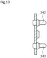
- FIG. 10 An electronic device according to a second embodiment of the present invention will be described with reference to FIG. 10 .
- the redundant descriptions of the same configuration as in the first embodiment will be omitted.
- FIG. 10 for convenience of explanation, only the circuit board which is a member on the load side and the positive terminal and the negative terminal on the load side are illustrated.
- the shape of the tips of a positive terminal 242 and a negative terminal 243 on the load side where the electrical contacts are formed forms a curved surface shape.
- the shape of the tips of the positive terminal 242 and the negative terminal 243 on the load side on which the electrical contacts are formed forms a curved surface shape, they are not likely to be damaged due to repeated work such as battery replacement, and the inclination between the positive terminal 242 and the negative terminal 243 and the positive electrode 10a and the negative electrode 10b of the battery 10 can be absorbed.
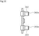
- FIG. 11 An electronic device according to a third embodiment of the present invention will be described with reference to FIG. 11 .
- the redundant descriptions of the same configuration as in the first embodiment will be omitted.
- FIG. 11 for convenience of explanation, only the circuit board which is a member on the load side and the positive terminal and the negative terminal on the load side are illustrated.
- the shape of the tips of a positive terminal 342 and a negative terminal 343 on the load side on which the electrical contacts are formed forms an uneven shape with a plurality of pointed projections 342a and 343a, respectively.
- the shape of the tips of the positive terminal 342 and the negative terminal 343 on the load side on which the electrical contacts are formed forms an uneven shape with the plurality of pointed projections 342a and 343a, respectively, the contact points with the positive electrode 10a and the negative electrode 10b of the battery 10 can be increased to distribute the stress. Accordingly, surface damage to the electrical contacts of the positive terminal 342 and the negative terminal 343 on the load side due to rattling of the battery 10 is prevented.
- the electronic device according to the present invention is not limited to the pressure sensor, and may be applied to other sensors or electronic devices other than sensors as long as it includes a battery as the power source.
- the electronic device may be configured such that a battery other than the pack lithium battery described above, for example, a button cell, an AA battery, a AAA battery, a square battery, and a coin battery can be held by the battery holder.
- a battery other than the pack lithium battery described above for example, a button cell, an AA battery, a AAA battery, a square battery, and a coin battery can be held by the battery holder.
- the present invention may be limited to this, and the wall portion standing at one end of the battery holder in the longitudinal direction may be provided with electrode terminals which are electrically connected to the battery and can be brought into contact with the positive terminal and the negative terminal on the load side. Further, as long as the positive terminal and the negative terminal on the battery side are arranged side by side in the vertical direction, the left and right positions thereof may not be the same.
- tip shape of the positive terminal and the negative terminal on the load side may form other tip shapes other than the shapes illustrated in the first to third embodiments.
- the positive terminal and the negative terminal on the load side may not be configured as probe pins, and may be configured as other electrode terminals such as leaf springs and coil springs.
- the battery holder is described as being provided with a projection, but the present invention is not limited to this, and the switch may be configured to be pressed by the outer surface of the wall portion of the battery holder by increasing the amount of projection of the switch.
- the switch may not be configured as a push momentary switch, and may be configured as other switches such as a reed switch.
- the switch may be provided not on a member on the load side but on a member on the battery side, for example, on the battery holder.
- the mode in which in the process of attachment and detachment of the battery, the positive terminal and the negative terminal on the load side are brought into contact with and separated from the positive terminal and the negative terminal on the battery side substantially at the same time, and the electrical connection/disconnection between the positive terminal on the battery side and the positive terminal on the load side is switched by the switch has been described, but the present invention is not limited to this, and the switch may not be provided and the amount of projection of the negative terminal on the load side may be configured to be larger than the amount of projection of the positive terminal on the load side.
- the negative terminal on the load side can be brought into contact with the negative terminal on the battery side before the positive terminal on the load side, and the positive terminal on the load side can be then brought into contact with the positive terminal on the battery side.
- the positive terminal on the load side can be first separated from the positive terminal on the battery side, and the negative terminal on the load side can be then separated from the negative terminal on the battery side. Accordingly, the reference potential of the circuit can always be determined due to the electrical connection between the negative terminal on the load side and the negative terminal on the battery side.
- processing chip and the wireless chip constituting the circuit unit may be provided at any position on the circuit board.
- the electronic device according to the present invention is not limited to the one in which the battery holder for holding the battery is attached to and detached from the body of the electronic device, but may be the one in which the battery is directly attached to and detached from the body of the electronic device.
Landscapes
- Chemical & Material Sciences (AREA)
- Chemical Kinetics & Catalysis (AREA)
- Electrochemistry (AREA)
- General Chemical & Material Sciences (AREA)
- Engineering & Computer Science (AREA)
- Power Engineering (AREA)
- Life Sciences & Earth Sciences (AREA)
- Biophysics (AREA)
- Computer Hardware Design (AREA)
- Physics & Mathematics (AREA)
- General Physics & Mathematics (AREA)
- Battery Mounting, Suspending (AREA)
Applications Claiming Priority (2)
| Application Number | Priority Date | Filing Date | Title |
|---|---|---|---|
| JP2020144223 | 2020-08-28 | ||
| PCT/JP2021/029355 WO2022044778A1 (fr) | 2020-08-28 | 2021-08-06 | Instrument électronique |
Publications (2)
| Publication Number | Publication Date |
|---|---|
| EP4207453A1 true EP4207453A1 (fr) | 2023-07-05 |
| EP4207453A4 EP4207453A4 (fr) | 2024-08-14 |
Family
ID=80353154
Family Applications (1)
| Application Number | Title | Priority Date | Filing Date |
|---|---|---|---|
| EP21861206.7A Pending EP4207453A4 (fr) | 2020-08-28 | 2021-08-06 | Instrument électronique |
Country Status (5)
| Country | Link |
|---|---|
| US (1) | US20230341283A1 (fr) |
| EP (1) | EP4207453A4 (fr) |
| JP (1) | JP7739660B2 (fr) |
| CN (1) | CN115885416A (fr) |
| WO (1) | WO2022044778A1 (fr) |
Families Citing this family (1)
| Publication number | Priority date | Publication date | Assignee | Title |
|---|---|---|---|---|
| CN120731536A (zh) * | 2023-04-05 | 2025-09-30 | 铁三角有限公司 | 麦克风以及电池的收纳构造 |
Family Cites Families (6)
| Publication number | Priority date | Publication date | Assignee | Title |
|---|---|---|---|---|
| JPH0845490A (ja) * | 1994-08-04 | 1996-02-16 | Sony Corp | 電子機器 |
| JP3341227B2 (ja) * | 1995-02-22 | 2002-11-05 | 京セラ株式会社 | 電池パックの充電端子短絡防止装置 |
| US20070120524A1 (en) * | 2005-10-24 | 2007-05-31 | King Mo Shum | Battery charger for charging different types of battery pack |
| WO2008005325A2 (fr) * | 2006-06-30 | 2008-01-10 | Entegris, Inc. | Station d'accueil de porte-tranches |
| CN108110198A (zh) * | 2017-12-18 | 2018-06-01 | 浙江动新能源动力科技股份有限公司 | 一种带开关机构组合式电池包插片装置 |
| JP2019153485A (ja) | 2018-03-05 | 2019-09-12 | Kyb株式会社 | 電池ホルダ及びセンサユニット |
-
2021
- 2021-08-06 WO PCT/JP2021/029355 patent/WO2022044778A1/fr not_active Ceased
- 2021-08-06 EP EP21861206.7A patent/EP4207453A4/fr active Pending
- 2021-08-06 CN CN202180051203.1A patent/CN115885416A/zh active Pending
- 2021-08-06 US US18/022,461 patent/US20230341283A1/en active Pending
- 2021-08-06 JP JP2022545617A patent/JP7739660B2/ja active Active
Also Published As
| Publication number | Publication date |
|---|---|
| WO2022044778A1 (fr) | 2022-03-03 |
| EP4207453A4 (fr) | 2024-08-14 |
| JPWO2022044778A1 (fr) | 2022-03-03 |
| US20230341283A1 (en) | 2023-10-26 |
| JP7739660B2 (ja) | 2025-09-17 |
| CN115885416A (zh) | 2023-03-31 |
Similar Documents
| Publication | Publication Date | Title |
|---|---|---|
| KR100530723B1 (ko) | 전자기기의 전원공급장치 | |
| KR100438746B1 (ko) | 배터리팩 | |
| US7567058B2 (en) | Power tool having a main body and a battery pack detachably attached to the main body | |
| JP5334406B2 (ja) | 電源コネクタを備える携帯式電源 | |
| CN101728569B (zh) | 电池装置及电子设备 | |
| CN101901942B (zh) | 2种方形充电电池的充电器 | |
| EP0818836A2 (fr) | Interface de batterie pour appareil électrique | |
| US7727007B2 (en) | Mounting apparatus for battery | |
| EP4207453A1 (fr) | Instrument électronique | |
| US20230291058A1 (en) | Electronic device and battery holder | |
| WO2000079625A1 (fr) | Module de batterie remplaçable | |
| JP3258875B2 (ja) | 電池ユニット及びこれを具えた電子機器 | |
| WO2023238404A1 (fr) | Outil de coupe | |
| EP4195386A1 (fr) | Dispositif électronique | |
| US20240356177A1 (en) | Electronic device | |
| JP2008086162A (ja) | 充電台 | |
| CN118943678A (zh) | 电子装置 | |
| JPH07335271A (ja) | 電池電源装置 | |
| JPH10308199A (ja) | 電池パック | |
| JP4601976B2 (ja) | 電子機器 | |
| KR980009758U (ko) | 배터리 팩 | |
| KR20000012639U (ko) | 리모콘의 건전지 단자 접속장치 |
Legal Events
| Date | Code | Title | Description |
|---|---|---|---|
| STAA | Information on the status of an ep patent application or granted ep patent |
Free format text: STATUS: THE INTERNATIONAL PUBLICATION HAS BEEN MADE |
|
| PUAI | Public reference made under article 153(3) epc to a published international application that has entered the european phase |
Free format text: ORIGINAL CODE: 0009012 |
|
| STAA | Information on the status of an ep patent application or granted ep patent |
Free format text: STATUS: REQUEST FOR EXAMINATION WAS MADE |
|
| 17P | Request for examination filed |
Effective date: 20230223 |
|
| AK | Designated contracting states |
Kind code of ref document: A1 Designated state(s): AL AT BE BG CH CY CZ DE DK EE ES FI FR GB GR HR HU IE IS IT LI LT LU LV MC MK MT NL NO PL PT RO RS SE SI SK SM TR |
|
| DAV | Request for validation of the european patent (deleted) | ||
| DAX | Request for extension of the european patent (deleted) | ||
| REG | Reference to a national code |
Ref country code: DE Ref legal event code: R079 Free format text: PREVIOUS MAIN CLASS: H01M0050244000 Ipc: H02J0007000000 |
|
| A4 | Supplementary search report drawn up and despatched |
Effective date: 20240712 |
|
| RIC1 | Information provided on ipc code assigned before grant |
Ipc: H01M 50/574 20210101ALI20240708BHEP Ipc: H01M 50/244 20210101ALI20240708BHEP Ipc: H02J 7/00 20060101AFI20240708BHEP |