EP4207510A1 - Connecteur - Google Patents
Connecteur Download PDFInfo
- Publication number
- EP4207510A1 EP4207510A1 EP21861116.8A EP21861116A EP4207510A1 EP 4207510 A1 EP4207510 A1 EP 4207510A1 EP 21861116 A EP21861116 A EP 21861116A EP 4207510 A1 EP4207510 A1 EP 4207510A1
- Authority
- EP
- European Patent Office
- Prior art keywords
- locking
- lever
- housing
- locking portion
- apex
- Prior art date
- Legal status (The legal status is an assumption and is not a legal conclusion. Google has not performed a legal analysis and makes no representation as to the accuracy of the status listed.)
- Granted
Links
Images


Classifications
-
- H—ELECTRICITY
- H01—ELECTRIC ELEMENTS
- H01R—ELECTRICALLY-CONDUCTIVE CONNECTIONS; STRUCTURAL ASSOCIATIONS OF A PLURALITY OF MUTUALLY-INSULATED ELECTRICAL CONNECTING ELEMENTS; COUPLING DEVICES; CURRENT COLLECTORS
- H01R13/00—Details of coupling devices of the kinds covered by groups H01R12/70 or H01R24/00 - H01R33/00
- H01R13/62—Means for facilitating engagement or disengagement of coupling parts or for holding them in engagement
- H01R13/629—Additional means for facilitating engagement or disengagement of coupling parts, e.g. aligning or guiding means, levers, gas pressure electrical locking indicators, manufacturing tolerances
- H01R13/62933—Comprising exclusively pivoting lever
- H01R13/62955—Pivoting lever comprising supplementary/additional locking means
-
- H—ELECTRICITY
- H01—ELECTRIC ELEMENTS
- H01R—ELECTRICALLY-CONDUCTIVE CONNECTIONS; STRUCTURAL ASSOCIATIONS OF A PLURALITY OF MUTUALLY-INSULATED ELECTRICAL CONNECTING ELEMENTS; COUPLING DEVICES; CURRENT COLLECTORS
- H01R13/00—Details of coupling devices of the kinds covered by groups H01R12/70 or H01R24/00 - H01R33/00
- H01R13/62—Means for facilitating engagement or disengagement of coupling parts or for holding them in engagement
- H01R13/629—Additional means for facilitating engagement or disengagement of coupling parts, e.g. aligning or guiding means, levers, gas pressure electrical locking indicators, manufacturing tolerances
- H01R13/62933—Comprising exclusively pivoting lever
-
- H—ELECTRICITY
- H01—ELECTRIC ELEMENTS
- H01R—ELECTRICALLY-CONDUCTIVE CONNECTIONS; STRUCTURAL ASSOCIATIONS OF A PLURALITY OF MUTUALLY-INSULATED ELECTRICAL CONNECTING ELEMENTS; COUPLING DEVICES; CURRENT COLLECTORS
- H01R13/00—Details of coupling devices of the kinds covered by groups H01R12/70 or H01R24/00 - H01R33/00
- H01R13/62—Means for facilitating engagement or disengagement of coupling parts or for holding them in engagement
- H01R13/629—Additional means for facilitating engagement or disengagement of coupling parts, e.g. aligning or guiding means, levers, gas pressure electrical locking indicators, manufacturing tolerances
- H01R13/62933—Comprising exclusively pivoting lever
- H01R13/62938—Pivoting lever comprising own camming means
Definitions
- a connector includes: a housing; and a lever that is supported by the housing and rotates from a temporary locking position to a main locking position to progressively fit the housing together with a mating housing, wherein one of the housing and the lever is provided with a first locking portion capable of flexible deformation and another of the housing and the lever is provided with a second locking portion, the first locking portion has a first apex portion and a first locking surface that is connected to the first apex portion, the second locking portion has a second locking surface that contacts the first locking portion and stops the lever at the temporary locking position, and the second locking surface has an inclined side which is disposed, in a state where the first locking portion has bent due to interference between the first apex portion and the second locking portion, so as to be inclined from the first apex portion toward the first locking surface.
- the second locking surface may include a locking side that intersects the inclined side with a second apex portion in between, and when the first locking portion is in a natural state at the temporary locking position, the locking side may be disposed so as to face and contact the first locking surface in parallel or at a shallower angle of inclination than the inclined side.
- the housing may include a housing-side locking portion
- the lever may include a lever-side locking portion that is locked to the housing-side locking portion at the temporary locking position
- one of the housing-side locking portion and the lever-side locking portion may be capable of flexible deformation
- a locking state of the housing-side locking portion and the lever-side locking portion may be released by a release portion of the mating housing
- a gap which allows the one of the housing-side locking portion and the lever-side locking portion to deform, may be formed between the lever-side locking portion and the housing-side locking portion
- the lever may be capable of rotating with respect to the housing within a range of the gap at the temporary locking position.
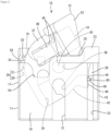
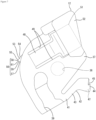
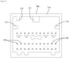
- the housing 11 is made of synthetic resin and formed in the overall shape of a square block. As depicted in FIG. 4 , the housing 11 is fitted inside the hood portion 110. As depicted in FIG. 1 , a plurality of female terminal fittings 20 are housed in the housing 11 (only one female terminal fitting 20 is illustrated in FIG. 1 ). Each female terminal fitting 20 is disposed at a position corresponding to a male terminal fitting 120. Each female terminal fitting 20 are connected to one end of an electric wire 90.
- the housing 11 has a housing portion 14 capable of housing the lever 12.
- the housing portion 14 is provided above a cavity region that houses the female terminal fittings 20.
- the housing portion 14 is delimited by the left and right side walls 16 and 17 and a top wall 18 (see FIG. 2 ) of the housing 11.
- the housing 11 has a locking portion 19 that protrudes inside the housing portion 14.
- a support shaft 62 that supports the lever 12 is disposed so as to protrude.
- the side wall 17 on the other side in the width direction has a pair of upper and lower slits 27 at an upper end portion that delimits the accommodating portion 14. Both slits 27 extend in the front-rear direction and are open to the rear at a rear end side of the upper end portion of the side wall 17.
- the first rising surface 33 is connected to an inner surface of the elastic portion 29 (which is the inner surface of the side wall 17), and is linearly inclined inward in the width direction with respect to the inner surface of the elastic portion 29 so as to extend deeper inside the housing portion 14 toward the rear.
- a surface direction of the first rising surface 33 and a surface direction of the first locking surface 32 intersect each other at an acute angle with the first apex portion 34 positioned in between.
- the first apex portion 34 is curved in an arc from the first locking surface 32 to the first rising surface 33.
- the first apex portion 34 intersects the first locking surface 32 and the first rising surface 33, and is formed as a curved surface whose radius of curvature is smaller than that of the curved portion 35.
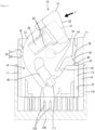
- the lever main body 37 has the cam channel 39 that is open on an upper-side plate surface.
- the cam channel 39 is also open at an outer peripheral edge of the lever main body 37.
- the cam follower 111 of the mating housing 100 enters the entrance of the cam channel 39.
- the cam follower 111 maintains sliding contact with a channel surface of the cam channel 39, which pulls the mating housing 100 toward the housing 11 and progressively fits the two housings 11 and 100 together.
- the cam follower 111 becomes disposed at the inner end of the cam channel 39 and the two housings 11 and 100 become properly fitted together.
- the respective female terminal fittings 20 and the respective male terminal fittings 120 are electrically connected.
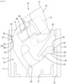
- the locking main body 44 has a locking recess 45 in the form of an L-shaped notch. As depicted in FIG. 3 , at the temporary locking position, the locking recess 45 faces a front end angled region 46 formed from an inner surface to a front surface of the housing-side locking portion 26. At a corner on a front end, the locking main body 44 has a relief recess 47 shaped so that a lower surface side is diagonally cut out.
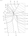
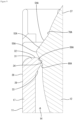
- the second rising surface 54 is connected to the top portion 55 on the opposite side (or rear side) to the side in which the lever 12 rotates toward the main locking position. As depicted in FIG. 6 , the second rising surface 54 is linearly disposed at a constant inclination angle from a connecting position 70 on the outer peripheral edge of the lever main body 37 to the top portion 55. The second rising surface 54 is an inclined surface with a gentle inclination angle with respect to the tangential direction at the connecting position 70 on the outer peripheral edge of the lever main body 37.
- the locking recess 45 of the lever-side locking portion 42 is disposed so as to be capable of fitting together with and locking on the front end angled region 46 of the housing-side locking portion 26.
- the locking side 59 of the second locking surface 56 is disposed so as to face and be capable of locking on the first locking surface 32.
- the locking side 59 of the second locking surface 56 is disposed so as to contact a front end region (that is, a first apex portion 34-side region) of the first locking surface 32 at a gentle angle of inclination or in parallel. By doing so, rotation of the lever 12 from the temporary locking position toward the main locking position is restricted.
- the first apex portion 34 slides on the inclined side 58 and becomes displaced toward the second apex portion 61. As this happens, bending of the elastic portion 29 will become automatically eliminated.
- the elastic portion 29 returns to the natural state.
- the elastic portion 29 has returned to the natural state, as depicted in FIG. 5 , the first locking surface 32 will face the locking side 59 of the second locking surface 56 so as to be lockable.
- FIGS. 9 and 10 a second embodiment of the present disclosure will be described with reference to FIGS. 9 and 10 .
- the shape of a second locking portion 53A differs to the first embodiment described above.
- Other elements are the same as in the first embodiment.
- identical or corresponding structures as those in the first embodiment have been assigned the same reference numerals and redundant description is omitted.
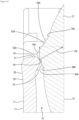
- the second rising surface 54A is linearly disposed at a constant inclination angle from a connecting position 70A on the outer peripheral edge of the lever main body 37 to the top portion 55A.
- the second rising surface 54A is an inclined surface with a gentle angle of inclination with respect to the tangential direction at the connecting position 70A on the outer peripheral edge of the lever main body 37.
- the length (that is, the length in the inclined direction) of the second rising surface 54A is shorter than the length of the second rising surface 54A in the first embodiment.
- the angle of inclination of the second locking surface 56A is larger than the angle of inclination of the inclined side 58A in the first embodiment and smaller than the angle of inclination of the locking side 59 in the first embodiment.
- the length of the second locking surface 56A is shorter than the length of the second rising surface 54A.
Landscapes
- Details Of Connecting Devices For Male And Female Coupling (AREA)
Applications Claiming Priority (2)
| Application Number | Priority Date | Filing Date | Title |
|---|---|---|---|
| JP2020142474A JP7437614B2 (ja) | 2020-08-26 | 2020-08-26 | コネクタ |
| PCT/JP2021/028206 WO2022044688A1 (fr) | 2020-08-26 | 2021-07-29 | Connecteur |
Publications (3)
| Publication Number | Publication Date |
|---|---|
| EP4207510A1 true EP4207510A1 (fr) | 2023-07-05 |
| EP4207510A4 EP4207510A4 (fr) | 2024-02-14 |
| EP4207510B1 EP4207510B1 (fr) | 2025-10-15 |
Family
ID=80353075
Family Applications (1)
| Application Number | Title | Priority Date | Filing Date |
|---|---|---|---|
| EP21861116.8A Active EP4207510B1 (fr) | 2020-08-26 | 2021-07-29 | Connecteur |
Country Status (5)
| Country | Link |
|---|---|
| US (1) | US12368268B2 (fr) |
| EP (1) | EP4207510B1 (fr) |
| JP (1) | JP7437614B2 (fr) |
| CN (1) | CN116057787B (fr) |
| WO (1) | WO2022044688A1 (fr) |
Families Citing this family (1)
| Publication number | Priority date | Publication date | Assignee | Title |
|---|---|---|---|---|
| JP7790278B2 (ja) * | 2022-06-10 | 2025-12-23 | 住友電装株式会社 | レバー式コネクタ |
Family Cites Families (12)
| Publication number | Priority date | Publication date | Assignee | Title |
|---|---|---|---|---|
| JP3758525B2 (ja) * | 2001-05-24 | 2006-03-22 | 住友電装株式会社 | レバー式コネクタ |
| DE10223928A1 (de) * | 2001-05-29 | 2003-01-23 | Sumitomo Wiring Systems | Hebeltyp-Verbinder und Verfahren zum Zusammenbauen |
| JP4577209B2 (ja) * | 2005-12-26 | 2010-11-10 | 住友電装株式会社 | コネクタ |
| JP2010287427A (ja) * | 2009-06-11 | 2010-12-24 | Nissan Motor Co Ltd | 電源回路接続装置 |
| JP5978398B2 (ja) * | 2013-05-30 | 2016-08-24 | 矢崎総業株式会社 | コネクタ |
| JP6252068B2 (ja) | 2013-09-24 | 2017-12-27 | 矢崎総業株式会社 | レバー嵌合式コネクタ |
| JP6246646B2 (ja) * | 2014-03-31 | 2017-12-13 | タイコエレクトロニクスジャパン合同会社 | レバー式コネクタ |
| JP6332074B2 (ja) * | 2015-02-16 | 2018-05-30 | 住友電装株式会社 | レバー式コネクタ |
| US9608357B1 (en) * | 2015-09-11 | 2017-03-28 | Delphi Technologies, Inc. | Right angle connector with terminal contact protection |
| JP6571119B2 (ja) * | 2017-01-13 | 2019-09-04 | 矢崎総業株式会社 | コネクタ |
| JP6951664B2 (ja) * | 2018-01-25 | 2021-10-20 | 住友電装株式会社 | レバー式コネクタ |
| US10734755B2 (en) * | 2018-09-24 | 2020-08-04 | Te Connectivity Corporation | Electrical connector and connector assembly having a seal gland |
-
2020
- 2020-08-26 JP JP2020142474A patent/JP7437614B2/ja active Active
-
2021
- 2021-07-29 WO PCT/JP2021/028206 patent/WO2022044688A1/fr not_active Ceased
- 2021-07-29 EP EP21861116.8A patent/EP4207510B1/fr active Active
- 2021-07-29 CN CN202180050931.0A patent/CN116057787B/zh active Active
- 2021-07-29 US US18/021,501 patent/US12368268B2/en active Active
Also Published As
| Publication number | Publication date |
|---|---|
| WO2022044688A1 (fr) | 2022-03-03 |
| EP4207510A4 (fr) | 2024-02-14 |
| EP4207510B1 (fr) | 2025-10-15 |
| JP7437614B2 (ja) | 2024-02-26 |
| JP2022038143A (ja) | 2022-03-10 |
| CN116057787A (zh) | 2023-05-02 |
| US20230299539A1 (en) | 2023-09-21 |
| US12368268B2 (en) | 2025-07-22 |
| CN116057787B (zh) | 2026-04-14 |
Similar Documents
| Publication | Publication Date | Title |
|---|---|---|
| JP4688113B2 (ja) | コネクタ位置保証装置を有するレバー嵌合型コネクタ組立体 | |
| JP4457927B2 (ja) | コネクタ | |
| EP2454785B1 (fr) | Connecteur à contacts mâles et femelles avec un élément de blocage | |
| JP6424190B2 (ja) | レバー式コネクタ | |
| JP6492030B2 (ja) | コネクタ | |
| JP5945964B2 (ja) | コネクタ | |
| JP2006344473A (ja) | レバー式コネクタ | |
| JP3275290B2 (ja) | レバー式コネクタ | |
| JP6492029B2 (ja) | コネクタ | |
| JP2016213081A (ja) | レバー式コネクタ | |
| JP4497038B2 (ja) | レバー式コネクタ | |
| EP4207510B1 (fr) | Connecteur | |
| JP7424247B2 (ja) | コネクタ | |
| US20060270258A1 (en) | Connector fitting structure | |
| JP4492493B2 (ja) | レバー式コネクタ | |
| JP2015046245A (ja) | 中継端子および中継コネクタ | |
| US6953372B2 (en) | Connector with press-in terminal fittings and recessed bulges surrounding the terminal fittings | |
| US20250038455A1 (en) | Lever-type connector | |
| JP2022154811A (ja) | レバー式コネクタ | |
| JP7460293B2 (ja) | コネクタハウジング、cpa付きコネクタ、及びワイヤーハーネス | |
| JP2023170503A (ja) | Cpa取付け構造、cpa付きコネクタ、及びワイヤーハーネス | |
| JP2025050229A (ja) | コネクタ | |
| JP2024136811A (ja) | コネクタ | |
| JP2010257917A (ja) | ショート端子 | |
| JP2007305484A (ja) | コネクタ |
Legal Events
| Date | Code | Title | Description |
|---|---|---|---|
| STAA | Information on the status of an ep patent application or granted ep patent |
Free format text: STATUS: THE INTERNATIONAL PUBLICATION HAS BEEN MADE |
|
| PUAI | Public reference made under article 153(3) epc to a published international application that has entered the european phase |
Free format text: ORIGINAL CODE: 0009012 |
|
| STAA | Information on the status of an ep patent application or granted ep patent |
Free format text: STATUS: REQUEST FOR EXAMINATION WAS MADE |
|
| 17P | Request for examination filed |
Effective date: 20230220 |
|
| AK | Designated contracting states |
Kind code of ref document: A1 Designated state(s): AL AT BE BG CH CY CZ DE DK EE ES FI FR GB GR HR HU IE IS IT LI LT LU LV MC MK MT NL NO PL PT RO RS SE SI SK SM TR |
|
| DAV | Request for validation of the european patent (deleted) | ||
| DAX | Request for extension of the european patent (deleted) | ||
| REG | Reference to a national code |
Ref country code: DE Free format text: PREVIOUS MAIN CLASS: H01R0013631000 Ref country code: DE Ref legal event code: R079 Ref document number: 602021040606 Country of ref document: DE Free format text: PREVIOUS MAIN CLASS: H01R0013631000 Ipc: H01R0013629000 |
|
| A4 | Supplementary search report drawn up and despatched |
Effective date: 20240117 |
|
| RIC1 | Information provided on ipc code assigned before grant |
Ipc: H01R 13/629 20060101AFI20240111BHEP |
|
| GRAP | Despatch of communication of intention to grant a patent |
Free format text: ORIGINAL CODE: EPIDOSNIGR1 |
|
| STAA | Information on the status of an ep patent application or granted ep patent |
Free format text: STATUS: GRANT OF PATENT IS INTENDED |
|
| INTG | Intention to grant announced |
Effective date: 20250604 |
|
| GRAS | Grant fee paid |
Free format text: ORIGINAL CODE: EPIDOSNIGR3 |
|
| GRAA | (expected) grant |
Free format text: ORIGINAL CODE: 0009210 |
|
| STAA | Information on the status of an ep patent application or granted ep patent |
Free format text: STATUS: THE PATENT HAS BEEN GRANTED |
|
| AK | Designated contracting states |
Kind code of ref document: B1 Designated state(s): AL AT BE BG CH CY CZ DE DK EE ES FI FR GB GR HR HU IE IS IT LI LT LU LV MC MK MT NL NO PL PT RO RS SE SI SK SM TR |
|
| REG | Reference to a national code |
Ref country code: GB Ref legal event code: FG4D Ref country code: CH Ref legal event code: F10 Free format text: ST27 STATUS EVENT CODE: U-0-0-F10-F00 (AS PROVIDED BY THE NATIONAL OFFICE) Effective date: 20251015 |
|
| REG | Reference to a national code |
Ref country code: DE Ref legal event code: R096 Ref document number: 602021040606 Country of ref document: DE |
|
| REG | Reference to a national code |
Ref country code: IE Ref legal event code: FG4D |
|
| REG | Reference to a national code |
Ref country code: NL Ref legal event code: MP Effective date: 20251015 |
|
| REG | Reference to a national code |
Ref country code: AT Ref legal event code: MK05 Ref document number: 1847893 Country of ref document: AT Kind code of ref document: T Effective date: 20251015 |
|
| PG25 | Lapsed in a contracting state [announced via postgrant information from national office to epo] |
Ref country code: NL Free format text: LAPSE BECAUSE OF FAILURE TO SUBMIT A TRANSLATION OF THE DESCRIPTION OR TO PAY THE FEE WITHIN THE PRESCRIBED TIME-LIMIT Effective date: 20251015 |
|
| PG25 | Lapsed in a contracting state [announced via postgrant information from national office to epo] |
Ref country code: ES Free format text: LAPSE BECAUSE OF FAILURE TO SUBMIT A TRANSLATION OF THE DESCRIPTION OR TO PAY THE FEE WITHIN THE PRESCRIBED TIME-LIMIT Effective date: 20251015 |
|
| REG | Reference to a national code |
Ref country code: LT Ref legal event code: MG9D |
|
| PG25 | Lapsed in a contracting state [announced via postgrant information from national office to epo] |
Ref country code: NO Free format text: LAPSE BECAUSE OF FAILURE TO SUBMIT A TRANSLATION OF THE DESCRIPTION OR TO PAY THE FEE WITHIN THE PRESCRIBED TIME-LIMIT Effective date: 20260115 |
|
| PG25 | Lapsed in a contracting state [announced via postgrant information from national office to epo] |
Ref country code: HR Free format text: LAPSE BECAUSE OF FAILURE TO SUBMIT A TRANSLATION OF THE DESCRIPTION OR TO PAY THE FEE WITHIN THE PRESCRIBED TIME-LIMIT Effective date: 20251015 Ref country code: AT Free format text: LAPSE BECAUSE OF FAILURE TO SUBMIT A TRANSLATION OF THE DESCRIPTION OR TO PAY THE FEE WITHIN THE PRESCRIBED TIME-LIMIT Effective date: 20251015 Ref country code: FI Free format text: LAPSE BECAUSE OF FAILURE TO SUBMIT A TRANSLATION OF THE DESCRIPTION OR TO PAY THE FEE WITHIN THE PRESCRIBED TIME-LIMIT Effective date: 20251015 |
|
| PG25 | Lapsed in a contracting state [announced via postgrant information from national office to epo] |
Ref country code: RS Free format text: LAPSE BECAUSE OF FAILURE TO SUBMIT A TRANSLATION OF THE DESCRIPTION OR TO PAY THE FEE WITHIN THE PRESCRIBED TIME-LIMIT Effective date: 20260115 |
|
| PG25 | Lapsed in a contracting state [announced via postgrant information from national office to epo] |
Ref country code: IS Free format text: LAPSE BECAUSE OF FAILURE TO SUBMIT A TRANSLATION OF THE DESCRIPTION OR TO PAY THE FEE WITHIN THE PRESCRIBED TIME-LIMIT Effective date: 20260215 |
|
| PG25 | Lapsed in a contracting state [announced via postgrant information from national office to epo] |
Ref country code: PT Free format text: LAPSE BECAUSE OF FAILURE TO SUBMIT A TRANSLATION OF THE DESCRIPTION OR TO PAY THE FEE WITHIN THE PRESCRIBED TIME-LIMIT Effective date: 20260216 |
|
| PG25 | Lapsed in a contracting state [announced via postgrant information from national office to epo] |
Ref country code: PL Free format text: LAPSE BECAUSE OF FAILURE TO SUBMIT A TRANSLATION OF THE DESCRIPTION OR TO PAY THE FEE WITHIN THE PRESCRIBED TIME-LIMIT Effective date: 20251015 |
|
| PG25 | Lapsed in a contracting state [announced via postgrant information from national office to epo] |
Ref country code: LV Free format text: LAPSE BECAUSE OF FAILURE TO SUBMIT A TRANSLATION OF THE DESCRIPTION OR TO PAY THE FEE WITHIN THE PRESCRIBED TIME-LIMIT Effective date: 20251015 |