EP4207552A1 - Schnellladeverfahren und -system, endgerät und ladegerät - Google Patents
Schnellladeverfahren und -system, endgerät und ladegerät Download PDFInfo
- Publication number
- EP4207552A1 EP4207552A1 EP23157715.6A EP23157715A EP4207552A1 EP 4207552 A1 EP4207552 A1 EP 4207552A1 EP 23157715 A EP23157715 A EP 23157715A EP 4207552 A1 EP4207552 A1 EP 4207552A1
- Authority
- EP
- European Patent Office
- Prior art keywords
- voltage
- charger
- battery
- value
- terminal
- Prior art date
- Legal status (The legal status is an assumption and is not a legal conclusion. Google has not performed a legal analysis and makes no representation as to the accuracy of the status listed.)
- Pending
Links
Images



Classifications
-
- H—ELECTRICITY
- H02—GENERATION; CONVERSION OR DISTRIBUTION OF ELECTRIC POWER
- H02J—ELECTRIC POWER NETWORKS; CIRCUIT ARRANGEMENTS OR SYSTEMS FOR SUPPLYING OR DISTRIBUTING ELECTRIC POWER; SYSTEMS FOR STORING ELECTRIC ENERGY
- H02J7/00—Circuit arrangements for charging or discharging batteries or for supplying loads from batteries
-
- G—PHYSICS
- G01—MEASURING; TESTING
- G01R—MEASURING ELECTRIC VARIABLES; MEASURING MAGNETIC VARIABLES
- G01R31/00—Arrangements for testing electric properties; Arrangements for locating electric faults; Arrangements for electrical testing characterised by what is being tested not provided for elsewhere
- G01R31/36—Arrangements for testing, measuring or monitoring the electrical condition of accumulators or electric batteries, e.g. capacity or state of charge [SoC]
- G01R31/3644—Constructional arrangements
- G01R31/3648—Constructional arrangements comprising digital calculation means, e.g. for performing an algorithm
-
- H—ELECTRICITY
- H01—ELECTRIC ELEMENTS
- H01M—PROCESSES OR MEANS, e.g. BATTERIES, FOR THE DIRECT CONVERSION OF CHEMICAL ENERGY INTO ELECTRICAL ENERGY
- H01M10/00—Secondary cells; Manufacture thereof
- H01M10/42—Methods or arrangements for servicing or maintenance of secondary cells or secondary half-cells
- H01M10/44—Methods for charging or discharging
-
- H—ELECTRICITY
- H02—GENERATION; CONVERSION OR DISTRIBUTION OF ELECTRIC POWER
- H02J—ELECTRIC POWER NETWORKS; CIRCUIT ARRANGEMENTS OR SYSTEMS FOR SUPPLYING OR DISTRIBUTING ELECTRIC POWER; SYSTEMS FOR STORING ELECTRIC ENERGY
- H02J7/00—Circuit arrangements for charging or discharging batteries or for supplying loads from batteries
- H02J7/60—Circuit arrangements for charging or discharging batteries or for supplying loads from batteries including safety or protection arrangements
- H02J7/61—Circuit arrangements for charging or discharging batteries or for supplying loads from batteries including safety or protection arrangements against overcharge
-
- H—ELECTRICITY
- H02—GENERATION; CONVERSION OR DISTRIBUTION OF ELECTRIC POWER
- H02J—ELECTRIC POWER NETWORKS; CIRCUIT ARRANGEMENTS OR SYSTEMS FOR SUPPLYING OR DISTRIBUTING ELECTRIC POWER; SYSTEMS FOR STORING ELECTRIC ENERGY
- H02J7/00—Circuit arrangements for charging or discharging batteries or for supplying loads from batteries
- H02J7/60—Circuit arrangements for charging or discharging batteries or for supplying loads from batteries including safety or protection arrangements
- H02J7/663—Circuit arrangements for charging or discharging batteries or for supplying loads from batteries including safety or protection arrangements using battery or load disconnect circuits
-
- H—ELECTRICITY
- H02—GENERATION; CONVERSION OR DISTRIBUTION OF ELECTRIC POWER
- H02J—ELECTRIC POWER NETWORKS; CIRCUIT ARRANGEMENTS OR SYSTEMS FOR SUPPLYING OR DISTRIBUTING ELECTRIC POWER; SYSTEMS FOR STORING ELECTRIC ENERGY
- H02J7/00—Circuit arrangements for charging or discharging batteries or for supplying loads from batteries
- H02J7/70—Circuit arrangements for charging or discharging batteries or for supplying loads from batteries characterised by the mechanical construction
-
- H—ELECTRICITY
- H02—GENERATION; CONVERSION OR DISTRIBUTION OF ELECTRIC POWER
- H02J—ELECTRIC POWER NETWORKS; CIRCUIT ARRANGEMENTS OR SYSTEMS FOR SUPPLYING OR DISTRIBUTING ELECTRIC POWER; SYSTEMS FOR STORING ELECTRIC ENERGY
- H02J7/00—Circuit arrangements for charging or discharging batteries or for supplying loads from batteries
- H02J7/80—Circuit arrangements for charging or discharging batteries or for supplying loads from batteries including monitoring or indicating arrangements
-
- H—ELECTRICITY
- H02—GENERATION; CONVERSION OR DISTRIBUTION OF ELECTRIC POWER
- H02J—ELECTRIC POWER NETWORKS; CIRCUIT ARRANGEMENTS OR SYSTEMS FOR SUPPLYING OR DISTRIBUTING ELECTRIC POWER; SYSTEMS FOR STORING ELECTRIC ENERGY
- H02J7/00—Circuit arrangements for charging or discharging batteries or for supplying loads from batteries
- H02J7/90—Regulation of charging or discharging current or voltage
- H02J7/933—Regulation of charging or discharging current or voltage the cycle being controlled or terminated in response to electric parameters
-
- H—ELECTRICITY
- H02—GENERATION; CONVERSION OR DISTRIBUTION OF ELECTRIC POWER
- H02J—ELECTRIC POWER NETWORKS; CIRCUIT ARRANGEMENTS OR SYSTEMS FOR SUPPLYING OR DISTRIBUTING ELECTRIC POWER; SYSTEMS FOR STORING ELECTRIC ENERGY
- H02J7/00—Circuit arrangements for charging or discharging batteries or for supplying loads from batteries
- H02J7/90—Regulation of charging or discharging current or voltage
- H02J7/96—Regulation of charging or discharging current or voltage in response to battery voltage
- H02J7/963—Regulation of charging or discharging current or voltage in response to battery voltage in response to battery voltage gradient
-
- H—ELECTRICITY
- H01—ELECTRIC ELEMENTS
- H01M—PROCESSES OR MEANS, e.g. BATTERIES, FOR THE DIRECT CONVERSION OF CHEMICAL ENERGY INTO ELECTRICAL ENERGY
- H01M10/00—Secondary cells; Manufacture thereof
- H01M10/42—Methods or arrangements for servicing or maintenance of secondary cells or secondary half-cells
- H01M10/425—Structural combination with electronic components, e.g. electronic circuits integrated to the outside of the casing
- H01M10/4257—Smart batteries, e.g. electronic circuits inside the housing of the cells or batteries
-
- H—ELECTRICITY
- H02—GENERATION; CONVERSION OR DISTRIBUTION OF ELECTRIC POWER
- H02J—ELECTRIC POWER NETWORKS; CIRCUIT ARRANGEMENTS OR SYSTEMS FOR SUPPLYING OR DISTRIBUTING ELECTRIC POWER; SYSTEMS FOR STORING ELECTRIC ENERGY
- H02J2207/00—Details of circuit arrangements for charging or discharging batteries or supplying loads from batteries
- H02J2207/20—Charging or discharging characterised by the power electronics converter
-
- H—ELECTRICITY
- H02—GENERATION; CONVERSION OR DISTRIBUTION OF ELECTRIC POWER
- H02J—ELECTRIC POWER NETWORKS; CIRCUIT ARRANGEMENTS OR SYSTEMS FOR SUPPLYING OR DISTRIBUTING ELECTRIC POWER; SYSTEMS FOR STORING ELECTRIC ENERGY
- H02J7/00—Circuit arrangements for charging or discharging batteries or for supplying loads from batteries
- H02J7/40—Circuit arrangements for charging or discharging batteries or for supplying loads from batteries characterised by the exchange of charge or discharge related data
- H02J7/42—Circuit arrangements for charging or discharging batteries or for supplying loads from batteries characterised by the exchange of charge or discharge related data with electronic devices having internal batteries, e.g. mobile phones
-
- Y—GENERAL TAGGING OF NEW TECHNOLOGICAL DEVELOPMENTS; GENERAL TAGGING OF CROSS-SECTIONAL TECHNOLOGIES SPANNING OVER SEVERAL SECTIONS OF THE IPC; TECHNICAL SUBJECTS COVERED BY FORMER USPC CROSS-REFERENCE ART COLLECTIONS [XRACs] AND DIGESTS
- Y02—TECHNOLOGIES OR APPLICATIONS FOR MITIGATION OR ADAPTATION AGAINST CLIMATE CHANGE
- Y02E—REDUCTION OF GREENHOUSE GAS [GHG] EMISSIONS, RELATED TO ENERGY GENERATION, TRANSMISSION OR DISTRIBUTION
- Y02E60/00—Enabling technologies; Technologies with a potential or indirect contribution to GHG emissions mitigation
- Y02E60/10—Energy storage using batteries
Definitions
- the present invention relates to a charging technology, and in particular, to a fast charging method and system, and an apparatus.
- terminals have increasingly powerful functions. Users may work and entertain themselves by using the terminals, and a terminal has become indispensable in people's daily life. However, a battery life of a terminal is limited, and a user needs to charge the terminal constantly.
- Embodiments of the present invention provide a fast charging method and system, a terminal, and a charger, to fast charge the terminal, thereby improving user experience.
- a first aspect of the present invention discloses a terminal, and the terminal includes a detection circuit, a conversion circuit, a transmitter, a receiver, a central processing unit CPU, a charging circuit, and a battery, where
- the conversion circuit is a buck circuit or a switch-capacitor conversion circuit.
- the CPU is configured to: compare the value of the voltage between the positive and negative electrodes with a first preset threshold, to obtain a comparison result, and generate the instruction information according to the comparison result.
- the CPU is further configured to: when detecting that the voltage between the positive and negative electrodes of the battery reaches a second preset threshold, send a break connection notification to the receiver; and the receiver is configured to break an electrical connection to the charger according to the break connection notification, where the first preset threshold is less than or equal to the second preset threshold.
- the terminal further includes a memory and a bus system.
- the processor and the memory are connected by using the bus system.
- the memory is configured to store an instruction.
- the processor is configured to execute the instruction stored in the memory, so that the terminal is fast charged.
- a second aspect of the present invention discloses a charger, and the charger includes a receiver, a voltage adjustment circuit, and a current adjustment circuit, where
- a third aspect of the present invention discloses another charger, and the charger includes a receiver, a voltage adjustment circuit, and a current adjustment circuit, where
- a fourth aspect of the present invention discloses a fast charging system, the system includes a terminal, a charger, and a connection cable, and the terminal is connected to the charger by using the connection cable, where
- the terminal generates instruction information according to the value of the voltage between the positive and negative electrodes of the battery includes: the terminal compares the value of the voltage between the positive and negative electrodes with a first preset threshold, to obtain a comparison result, and generates the instruction information according to the comparison result.
- the terminal in the system detects that the voltage between the positive and negative electrodes of the battery reaches a second preset threshold
- the terminal can break an electrical connection between the terminal and the charger, or may instruct the charger to enter a sleep mode, so that the charger stops supplying power to the terminal.
- the terminal may further actively disconnect the electrical connection to the charger, or may instruct the charger to enter a sleep mode, so that the charger stops supplying power to the terminal.
- a fifth aspect of the present invention discloses a fast charging method, and the method includes:
- the generating, by the terminal, instruction information according to the value of the voltage between the positive and negative electrodes of the battery includes: comparing, by the terminal, the value of the voltage between the positive and negative electrodes with a first preset threshold, to obtain a comparison result, and generating the instruction information according to the comparison result.
- the terminal breaks an electrical connection between the terminal and the charger or instructs the charger to stop charging.
- a sixth aspect of the present invention discloses another fast charging method, and the method includes:
- the technical solutions of the present invention provide a fast charging method and system, a terminal, and a charger.
- the instruction information is sent to the charger connected to the terminal, so as to instruct the charger to adjust the output voltage and the output current.
- the terminal converts the output voltage of the charger into 1/K times the output voltage, and converts the output current of the charger into K times the output current.
- the conversion circuit is a conversion circuit with a fixed conversion ratio.
- the conversion coefficient K is a constant value, and K is any real number greater than 1.
- the charging circuit in the terminal charges the battery with the 1/K times the output voltage and the K times the output current.
- the terminal can be fast charged by implementing the technical solutions provided in the present invention, thereby improving user experience.
- the present invention provides a fast charging system (FCS for short).
- FCS can implement fast charging.
- FIG. 1 For a detailed schematic diagram of the FCS, refer to FIG. 1 .
- the system includes a terminal 10, a charger 20, and a connection cable 30.
- the terminal 10 is connected to the charger 20 by using the connection cable 30.
- the system implements fast charging by using the following procedure.
- the terminal 10 is configured to obtain a value of a voltage between positive and negative electrodes of a battery in the terminal 10.
- a detection circuit may be formed by connecting the two ends of the battery, so that the value of the voltage between the positive and negative electrodes of the battery can be obtained at any time.
- the terminal may be an electronic device such as a mobile phone, a tablet computer, an intelligent wearable device, or a computer.
- the battery in the terminal is usually a lithium-ion battery.
- a type of the battery is not limited herein.
- the terminal 10 is configured to: generate instruction information according to the value of the voltage between the positive and negative electrodes of the battery, and send the instruction information to the charger 20.
- connection cable between the terminal 10 and the charger 20 has a communication function, and may be used for transferring information between the terminal 10 and the charger 20.
- connection cable there are communication lines (that is, a line D+ and a line D-) between the terminal 10 and the charger 20.
- Direct current voltages with various amplitudes are separately applied to the lines D+ and D-, and multiple status combinations are generated.
- Each state may represent one signal.
- (0 V, 0 V) represents that a charging current is 0 A.
- (0 V, 0.4 V) represents 0.5 A.
- (0.4 V, 0.4 V) represents 2 A.
- PWM voltages with a duty cycle are separately applied to the lines D+ and D-, and a pulse width is used to represent a signal.
- communication may be performed between the terminal 10 and the charger 20 in a wireless manner.
- the charger 20 is configured to: adjust a voltage value of an output voltage to K times the value of the voltage between the positive and negative electrodes of the battery according to the instruction information, determine a charging mode according to the instruction information, obtain a current value corresponding to the charging mode, and adjust an output current according to the corresponding current value, where K is any real number greater than 1.
- the instruction information includes the value V1 of the voltage between the positive and negative electrodes of the battery and V2, that is, K times the value of the voltage between the positive and negative electrodes of the battery. Because K is greater than 1, V2 is greater than V1.
- the charger directly adjusts the output voltage to V2, that is, K times the value of the voltage between the positive and negative electrodes of the battery.
- the instruction information includes the value V1 of the voltage between the positive and negative electrodes of the battery, and a voltage adjustment coefficient K is pre-stored in the charger. Therefore, the charger directly adjusts the output voltage to V2, that is, K times the value of the voltage between the positive and negative electrodes of the battery.
- the charger determines the charging mode according to the value V1 of the voltage between the positive and negative electrodes of the battery, then obtains the current value corresponding to the charging mode from a memory of the terminal, and adjusts the output current according to the corresponding current value.
- the terminal 10 is configured to: convert the output voltage of the charger 20 into 1/K times the output voltage, and convert the output current of the charger 20 into K times the output current, so that a charging circuit between the two ends of the battery charges the battery with the 1/K times the output voltage and the K times the output current, where K is a conversion coefficient of a conversion circuit with a fixed conversion ratio in the terminal and is a constant value.
- the voltage between the positive and negative electrodes of the battery may be obtained at any time, and a charging current may be adjusted according to the value of the voltage.
- the terminal 10 compares the obtained voltage value with a first preset threshold, obtains a comparison result, and generates the instruction information according to the comparison result, to instruct the charger to adjust the current.
- the terminal 10 detects that the voltage between the positive and negative electrodes of the battery reaches a second preset threshold, the terminal breaks an electrical connection between the terminal and the charger.
- the first preset threshold is less than or equal to the second preset threshold.
- the terminal in the FCS provided in this embodiment of the present invention uses a direct current/direct current (DC/DC) conversion manner with a fixed conversion ratio, works with a fixed maximum duty cycle, and continuously adjusts the output voltage and the output current of the charger based on a real-time voltage feedback of the battery, thereby effectively improving charging efficiency of the entire FCS and shortening a fast charging time.
- DC/DC direct current/direct current
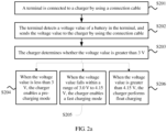
- a specific fast charging method is provided.
- the method may be applied to the FCS described in FIG. 1 . It is assumed that 3 V is a lower limit threshold of a fast charging voltage, 4.15 V is an upper limit threshold of the fast charging voltage, and a conversion coefficient K of a DC/DC conversion module with a fixed conversion ratio in a terminal is equal to 2, and the method includes the following steps.
- the terminal is connected to a charger by using a connection cable.
- the terminal detects a value of a voltage between positive and negative electrodes of a battery in the terminal, and sends the voltage value to the charger by using the connection cable.
- the charger determines whether the voltage value is greater than 3 V.
- the charger When the voltage value is less than 3 V, the charger enables a pre-charging mode.
- the pre-charging mode is as follows: When the voltage value is less than 3 V, the charger performs pre-charging with a small current, a selected pre-charging current is 0.2 C (a current range may be 0.05 C to 0.5 C). A current value of the pre-charging current may be preset at delivery, or may be manually set by a user within the current range. It should be noted that if a capacity of the battery is 3 Ah, 1 C represents 3 A.
- the fast charging mode is as follows: When the value of the voltage between the positive and negative electrodes of the battery falls within the range of 3.0 V to 4.15 V, the charger performs fast charging.
- the charger adjusts a specified charging current of 2.0 C (a current range may be 0.5 C to 10 C).
- a current value of the current may be preset at delivery, or may be manually set by a user within the current range.
- An output current of the charger is 2.0 C.
- a mobile phone side converts the output voltage V1 and the output current I1 of the charger by using the DC/DC conversion module with a fixed conversion ratio.
- the float charging may be understood as charging with a constant voltage or a small current.
- a charging current range is 0.01 C to 1.0 C.
- a current value of the current may be preset at delivery, or may be manually set by a user within the current range.
- a terminal 10 in the FCS includes a detection circuit 110, a conversion circuit 120, a transmitter 130, a battery 140, a Central Processing Unit (CPU) 150, a charging circuit 160, and a receiver 170.
- CPU Central Processing Unit
- the detection circuit 110 is configured to detect a value of a voltage between positive and negative electrodes of the battery 140.
- a switch Qb is serially connected to the battery. During charging, the switch Qb is turned on. When the voltage of the battery is being detected, the switch Qb is turned off. Both a charging current and a discharging current are 0, so that voltage drops of the cable and internal resistance drop to the minimum. Qd is turned on at the same time.
- the voltage of the battery is divided by R1R2 and sent to a back-end analog-to-digital converter or a comparator, to obtain the voltage of the battery.
- the CPU 150 is configured to generate instruction information according to the value of the voltage between the positive and negative electrodes of the battery 140.
- the transmitter 130 is configured to send the instruction information to a charger 20 connected to the terminal 10, so as to instruct the charger 20 to adjust an output voltage and an output current.
- the receiver 170 is configured to receive the output voltage and the output current transmitted from the charger, where the receiver is electrically connected to the charger.
- the conversion circuit 120 is configured to: convert the output voltage received by the receiver 170 into 1/K times the output voltage, and convert the output current received by the receiver 170 into K times the output current, where the conversion circuit 120 is a conversion circuit with a fixed conversion ratio, the conversion coefficient K is a constant value, and K is any real number greater than 1.
- the charging circuit 160 is configured to charge the battery 140 with the 1/K times the output voltage and the K times the output current.
- the conversion circuit is a buck circuit or a switch-capacitor conversion circuit.
- the conversion circuit 120 uses a buck manner with a fixed duty cycle.
- a buck with a fixed duty cycle switching transistors Q1 and Q2 form a bridge arm.
- Drive signals V1 and V2 drive Q1 and Q2 to be alternatively turned on, to convert a direct current voltage Vin into a pulse voltage with a fixed duty cycle, and implement a voltage drop with a conversion coefficient of K.
- the duty cycle is fixed at a maximum value, to implement efficient charging.
- multiple bucks may be connected in parallel according to a sequence of phases to form a multiphase buck.
- the DC/DC conversion module may be further a switch-capacitor converter.
- Four switching transistors in the switch-capacitor converter are connected in series.
- a capacitor C7 is connected between a midpoint of Q1Q2 and a midpoint of Q3Q4.
- V2 to V5 are drivers of the switching transistors.
- V2 and V5 are complementary.
- V3 and V4 are complementary.
- a 2:1 switch-capacitor converter may drop an input voltage to a half of the input voltage at a fixed ratio of 2:1. After conversion performed on Vin by the conversion circuit, an output voltage Vout ⁇ Vin/2. Switch-capacitor conversion does not need an inductor, and a loss can be significantly reduced. Therefore, conversion efficiency can be significantly improved, and a larger charging current can be implemented.
- the CPU 150 is further configured to: compare the voltage value obtained by the detection circuit 110 with a first preset threshold, to obtain a comparison result, and generate the instruction information according to the comparison result.
- the transmitter 130 is configured to send the instruction information to the charger.
- the instruction information is used to instruct the charger to adjust the output current.
- the first preset threshold is 3 V.
- the detection circuit 110 detects the value of the voltage between the positive and negative electrodes of the battery, and the detected value of the voltage between the positive and negative electrodes is 2.5 V.
- the CPU 150 determines that the value of the voltage between the positive and negative electrodes is less than the first preset threshold, and instructs the charger to perform charging in a slow charging manner. If the detected voltage value is 3.5 V, the CPU 150 determines that the value of the voltage between the positive and negative electrodes is greater than the first preset threshold, and instructs the charger to perform charging in a fast charging manner.
- the slow charging manner has a corresponding output current (which may be a current value, or may be a value range).
- the fast charging manner also has a corresponding output current (which may be a current value, or may be a value range).
- the CPU 150 is further configured to: when detecting that the voltage of the battery 140 reaches a second preset threshold, send a break connection notification to the receiver 170.
- the receiver 170 is configured to break an electrical connection to the charger according to the break connection notification.
- the CPU 150 may further instruct the charger 20 to enter a sleep mode, so that the charger stops supplying power.
- the detection circuit 110 may be further configured to detect a current of the battery 140 and a state of charge of the battery. When the current is excessively large or charges are consumed excessively quickly, the detection circuit 110 gives a notification on an interface of the terminal.
- the terminal 10 may further include a memory 180 and a bus system.
- the CPU 150 and the memory are connected by using the bus system.
- the memory is configured to store an instruction.
- the processor is configured to execute the instruction stored in the memory, so that the terminal 10 performs the fast charging method.
- the CPU 150 may be another general-purpose processor, a Digital Signal Processor (DSP), an Application Specific Integrated Circuit) (ASIC), a Field-Programmable Gate Array (FPGA) or another programmable logic device, a discrete gate or a transistor logic device, a discrete hardware component, or the like.
- the general-purpose processor may be a microprocessor, or the processor may be any conventional processor.
- the memory may include a read-only memory and a random access memory, and provide an instruction and data for the CPU.
- a part of the memory may further include a nonvolatile random access memory.
- the memory may further store information about a device type.
- the bus system may include a power bus, a control bus, a status signal bus, and the like.
- the charger 20 in the FCS includes a receiver 210, a voltage adjustment circuit 220, and a current adjustment circuit 230.
- the receiver 210 is configured to receive instruction information sent by the terminal 10, where the instruction information includes a value of a voltage between positive and negative electrodes of the battery in the terminal 10 and K times the value of the voltage between the positive and negative electrodes, and K is any real number greater than 1.
- the voltage adjustment circuit 220 is configured to adjust a voltage value of an output voltage to K times the value of the voltage between the positive and negative electrodes of the battery.
- the current adjustment circuit 230 is configured to: determine a charging mode according to the value of the voltage between the positive and negative electrodes of the battery, obtain a current value corresponding to the charging mode, and adjust an output current according to the corresponding current value.
- the charger is connected to a power supply. Therefore, the charger includes an alternating current/direct current conversion module, so as to convert an alternating current provided by the power supply into a direct current.
- the terminal uses a DC/DC conversion manner with a fixed conversion ratio, works with a fixed duty cycle, and continuously adjusts the output voltage and the output current of the charger based on a real-time voltage feedback of the battery. Conversion efficiency of the DC/DC conversion manner is higher, so that a charging current output to the battery on a mobile phone side can be larger, and charging efficiency of the entire FCS is effectively improved, thereby effectively shortening a fast charging time.
- an embodiment of the present invention further provides a charging method.
- the method includes a terminal side method and a charger side method.
- the fast charging method on a terminal side includes the following steps:
- the terminal generates the instruction information according to the value of the voltage between the positive and negative electrodes of the battery includes the following:
- the terminal compares the value of the voltage between the positive and negative electrodes with a first preset threshold, to obtain a comparison result, and generates the instruction information according to the comparison result. Further, it should be noted that the terminal 10 needs to continuously detect whether the battery is fully charged, and when the battery is fully charged, needs to instruct the charger 20 to stop charging or disconnect an electrical connection to the charger 20. Optionally, the terminal 10 may detect whether the voltage between the positive and negative electrodes of the battery reaches a second preset threshold, and when detecting that the voltage between the positive and negative electrodes of the battery reaches the second preset threshold, disconnects an electrical connection between the terminal and the charger.
- the fast charging method on a charger 20 side includes the following steps:
- the fast charging method on a charger 20 side further includes the following steps:
- the terminal uses a DC/DC conversion manner with a fixed conversion ratio, works with a fixed duty cycle, and continuously adjusts the output voltage and the output current of the charger based on a real-time voltage feedback of the battery. Conversion efficiency of the DC/DC conversion manner is higher, so that a charging current output to the battery on a mobile phone side can be larger, and charging efficiency of the entire FCS is effectively improved, thereby shortening a fast charging time.
- a charger and a mobile phone are used as an example for description.
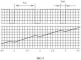
- FIG. 9 an upper part of FIG. 9 is a pulse current waveform, and a lower part of FIG. 9 is a waveform when a voltage of a battery becomes higher after charging.
- a horizontal coordinate represents a time, and a vertical coordinate represents a charging current.
- the charging current is a relatively large value, and the voltage of the battery rises.
- the current is 0 or a relatively small value, and the voltage of the battery drops down.
- the voltage of the battery may be detected.
- a current value during the period of T on may also vary according to the voltage of the battery. For example, at first, the voltage of the battery is 3 V, and a current during the period of T on is 8 A. When the voltage of the battery reaches 4.0 V, the current is adjusted to a small value: 6 A. When the voltage of the battery reaches 4.15 V, the current is adjusted to a small value: 3 A, until the battery is fully charged.
- a value of the period of T off may change. For example, when the voltage of the battery reaches 4.2 V, the period of T off gets longer as a battery level gets closer to a full battery level. The process in which the period of T off gets longer may be implemented by detecting the voltage of the battery.
- the voltage of the battery necessarily slightly exceeds 4.2 V. Then, after the pulse ends, the voltage of the battery starts to drop down, and when the voltage drops down to 4.18 V, another pulse comes.
- a higher battery level necessarily leads to a longer time for the voltage to drop down to 4.18 V. When the time is long enough, it is considered that the battery is fully charged, and an electrical connection between the terminal and the charger can be broken.
- the disclosed system, apparatus, and method may be implemented in other manners.
- the described apparatus embodiment is merely an example.
- the unit division is merely logical function division and may be other division in actual implementation.
- a plurality of units or components may be combined or integrated into another system, or some features may be ignored or not performed.
- the displayed or discussed mutual couplings or direct couplings or communication connections may be implemented by using some interfaces.
- the indirect couplings or communication connections between the apparatuses or units may be implemented in electronic, mechanical, or other forms.
- the units described as separate parts may or may not be physically separate, and parts displayed as units may or may not be physical units, may be located in one position, or may be distributed on a plurality of network units. Some or all of the units may be selected according to actual requirements to achieve the objectives of the solutions of the embodiments.
- function units in the embodiments of the present invention may be integrated into one processing unit, or each of the units may exist alone physically, or two or more units are integrated into one unit.
- the functions When the functions are implemented in the form of a software functional unit and sold or used as an independent product, the functions may be stored in a computer-readable storage medium. Based on such an understanding, the technical solutions of the present invention essentially, or the part contributing to the prior art, or some of the technical solutions may be implemented in a form of a software product.
- the software product is stored in a storage medium, and includes several instructions for instructing a computer device (which may be a personal computer, a server, or a network device) to perform all or some of the steps of the methods described in the embodiments of the present invention.
- the foregoing storage medium includes: any medium that can store program code, such as a USB flash drive, a removable hard disk, a read-only memory (ROM, Read-Only Memory), a random access memory (RAM, Random Access Memory), a magnetic disk, or an optical disc.
- program code such as a USB flash drive, a removable hard disk, a read-only memory (ROM, Read-Only Memory), a random access memory (RAM, Random Access Memory), a magnetic disk, or an optical disc.
Landscapes
- Engineering & Computer Science (AREA)
- Power Engineering (AREA)
- Physics & Mathematics (AREA)
- General Physics & Mathematics (AREA)
- Manufacturing & Machinery (AREA)
- Chemical & Material Sciences (AREA)
- Chemical Kinetics & Catalysis (AREA)
- Electrochemistry (AREA)
- General Chemical & Material Sciences (AREA)
- Charge And Discharge Circuits For Batteries Or The Like (AREA)
- Secondary Cells (AREA)
Applications Claiming Priority (4)
| Application Number | Priority Date | Filing Date | Title |
|---|---|---|---|
| CN201610218184.8A CN107231012B (zh) | 2016-04-08 | 2016-04-08 | 一种快速充电的方法、终端、充电器和系统 |
| EP17778601.9A EP3435511B1 (de) | 2016-04-08 | 2017-03-24 | Schnellladeverfahren, endgerät, ladegerät und system |
| EP19211984.0A EP3654487B1 (de) | 2016-04-08 | 2017-03-24 | Schnellladeverfahren und -system, endgerät und ladegerät |
| PCT/CN2017/078098 WO2017173937A1 (zh) | 2016-04-08 | 2017-03-24 | 一种快速充电的方法、终端、充电器和系统 |
Related Parent Applications (3)
| Application Number | Title | Priority Date | Filing Date |
|---|---|---|---|
| EP19211984.0A Division EP3654487B1 (de) | 2016-04-08 | 2017-03-24 | Schnellladeverfahren und -system, endgerät und ladegerät |
| EP19211984.0A Division-Into EP3654487B1 (de) | 2016-04-08 | 2017-03-24 | Schnellladeverfahren und -system, endgerät und ladegerät |
| EP17778601.9A Division EP3435511B1 (de) | 2016-04-08 | 2017-03-24 | Schnellladeverfahren, endgerät, ladegerät und system |
Publications (1)
| Publication Number | Publication Date |
|---|---|
| EP4207552A1 true EP4207552A1 (de) | 2023-07-05 |
Family
ID=59932828
Family Applications (3)
| Application Number | Title | Priority Date | Filing Date |
|---|---|---|---|
| EP23157715.6A Pending EP4207552A1 (de) | 2016-04-08 | 2017-03-24 | Schnellladeverfahren und -system, endgerät und ladegerät |
| EP17778601.9A Active EP3435511B1 (de) | 2016-04-08 | 2017-03-24 | Schnellladeverfahren, endgerät, ladegerät und system |
| EP19211984.0A Active EP3654487B1 (de) | 2016-04-08 | 2017-03-24 | Schnellladeverfahren und -system, endgerät und ladegerät |
Family Applications After (2)
| Application Number | Title | Priority Date | Filing Date |
|---|---|---|---|
| EP17778601.9A Active EP3435511B1 (de) | 2016-04-08 | 2017-03-24 | Schnellladeverfahren, endgerät, ladegerät und system |
| EP19211984.0A Active EP3654487B1 (de) | 2016-04-08 | 2017-03-24 | Schnellladeverfahren und -system, endgerät und ladegerät |
Country Status (8)
| Country | Link |
|---|---|
| US (4) | US10734830B2 (de) |
| EP (3) | EP4207552A1 (de) |
| JP (1) | JP6669931B2 (de) |
| KR (1) | KR102220839B1 (de) |
| CN (3) | CN110212599B (de) |
| DE (1) | DE202017007596U1 (de) |
| ES (2) | ES2951335T3 (de) |
| WO (1) | WO2017173937A1 (de) |
Families Citing this family (15)
| Publication number | Priority date | Publication date | Assignee | Title |
|---|---|---|---|---|
| CN107231013B (zh) * | 2016-05-24 | 2019-01-15 | 华为技术有限公司 | 一种充电的方法、终端、充电器和系统 |
| CN109690900B (zh) * | 2016-06-01 | 2021-03-23 | 华为技术有限公司 | 一种充电的方法及终端 |
| CN108258348B (zh) * | 2018-02-13 | 2022-04-29 | 中兴通讯股份有限公司 | 充电方法及装置、系统、充电电路、终端、充电系统 |
| WO2019232775A1 (zh) | 2018-06-08 | 2019-12-12 | 华为技术有限公司 | 一种无线充电装置以及使用所述装置的终端 |
| CN108849611A (zh) * | 2018-06-14 | 2018-11-23 | 北京北科驿唐科技有限公司 | 一种用于宠物防丢器的省电方法和装置 |
| CN110957773B (zh) * | 2019-10-29 | 2022-04-01 | 大族激光科技产业集团股份有限公司 | 一种高压直流充电系统 |
| CN111416408A (zh) * | 2020-03-09 | 2020-07-14 | 长兴永烜机械有限公司 | 一种充电器及其充电控制方法 |
| CN111509962A (zh) * | 2020-05-26 | 2020-08-07 | 深圳市雷能混合集成电路有限公司 | 一种防电流反灌的控制方法、装置和电源设备 |
| TWI740615B (zh) * | 2020-08-19 | 2021-09-21 | 僑威科技股份有限公司 | 行動電子裝置之快充式充電裝置 |
| CN114079317B (zh) * | 2020-08-19 | 2024-02-02 | 广州贵冠科技有限公司 | 移动电子装置的快充式充电装置 |
| JP6865879B1 (ja) | 2020-09-07 | 2021-04-28 | 日本たばこ産業株式会社 | エアロゾル発生システム、吸引器用コントローラ、および電源装置 |
| WO2022085924A1 (ko) * | 2020-10-19 | 2022-04-28 | 주식회사 브로나인 | 연결된 전자기기의 전력규격 분석에 기초한 전력 공급 장치, 방법 및 프로그램 |
| CN112491112A (zh) * | 2020-11-18 | 2021-03-12 | 惠州Tcl移动通信有限公司 | 移动终端充电器及移动终端充电器充电方法 |
| CN115037012B (zh) * | 2022-07-01 | 2026-02-13 | 安克创新科技股份有限公司 | 电池的充电控制方法、系统、设备及存储介质 |
| CN118826196A (zh) * | 2023-04-18 | 2024-10-22 | 中兴通讯股份有限公司 | 充电方法、电子设备、计算机可读介质 |
Citations (5)
| Publication number | Priority date | Publication date | Assignee | Title |
|---|---|---|---|---|
| US20090174366A1 (en) * | 2008-01-09 | 2009-07-09 | Freescale Semiconductor, Inc. | Multiple Function Switching Regulator for Use in Mobile Electronic Devices |
| US20140300321A1 (en) * | 2013-04-04 | 2014-10-09 | Samsung Electronics Co., Ltd. | Method for controlling charging of electronic device, and electronic device and charging device supporting the same |
| WO2015113333A1 (zh) * | 2014-01-28 | 2015-08-06 | 广东欧珀移动通信有限公司 | 电子设备充电控制装置及方法 |
| WO2015113349A1 (zh) * | 2014-01-28 | 2015-08-06 | 广东欧珀移动通信有限公司 | 电池充电装置及方法 |
| EP2942853A1 (de) * | 2013-01-18 | 2015-11-11 | Huawei Device Co., Ltd. | Ladeverfahren, mobile vorrichtung, ladevorrichtung und ladesystem |
Family Cites Families (40)
| Publication number | Priority date | Publication date | Assignee | Title |
|---|---|---|---|---|
| CA2022802A1 (en) * | 1989-12-05 | 1991-06-06 | Steven E. Koenck | Fast battery charging system and method |
| JP2914259B2 (ja) * | 1995-12-14 | 1999-06-28 | 日本電気株式会社 | 携帯電子機器と携帯電子機器の充電制御方法 |
| JPH11103538A (ja) * | 1997-09-27 | 1999-04-13 | My Way Giken Kk | 光発電システム |
| US7336054B2 (en) * | 1998-08-14 | 2008-02-26 | Milwaukee Electric Tool Corporation | Apparatus and method of activating a microcontroller |
| US6172481B1 (en) | 1999-09-02 | 2001-01-09 | Qualcomm Incorporated | Method and apparatus for rapid charging batteries under sub-optimal interconnect conditions |
| US6946817B2 (en) * | 2001-03-01 | 2005-09-20 | Research In Motion Limited | System and method for powering and charging a mobile communication device |
| CA2456608C (en) * | 2003-01-31 | 2009-01-06 | Universidad Tecnica Federico Santa Maria | A system to determine and analyze the dynamic internal load in revolving mills, for mineral grinding |
| US7135836B2 (en) * | 2003-03-28 | 2006-11-14 | Power Designers, Llc | Modular and reconfigurable rapid battery charger |
| US20050096518A1 (en) * | 2003-10-31 | 2005-05-05 | Yu-Hong Chang | Biological test system |
| JP4820257B2 (ja) * | 2006-09-28 | 2011-11-24 | パナソニック株式会社 | 昇圧コンバータ |
| US7937058B2 (en) * | 2006-10-18 | 2011-05-03 | Freescale Semiconductor, Inc. | Controlling the bandwidth of an analog filter |
| WO2008074158A1 (en) * | 2006-12-21 | 2008-06-26 | Icera Canada ULC | Closed-loop digital power control for a wireless transmitter |
| US8427113B2 (en) | 2007-08-01 | 2013-04-23 | Intersil Americas LLC | Voltage converter with combined buck converter and capacitive voltage divider |
| US8405361B2 (en) | 2007-09-21 | 2013-03-26 | Qualcomm Incorporated | System and method for charging a rechargeable battery |
| US8278871B2 (en) * | 2009-04-03 | 2012-10-02 | Medtronic, Inc. | Open-loop recharge for an implantable medical device |
| KR101576182B1 (ko) * | 2009-05-28 | 2015-12-10 | 삼성전자주식회사 | 태양전지를 구비하는 휴대 단말기의 충전 제어 장치 및 방법 |
| US20110089899A1 (en) * | 2009-10-20 | 2011-04-21 | Xin Xu | Lithium-ion auto startup storage battery with a supercapacitor function |
| TWM385858U (en) * | 2010-02-12 | 2010-08-01 | Fu Da Tong Technology Co Ltd | Frequency conversion type wireless power supply and charging device |
| EP2424067A1 (de) * | 2010-08-26 | 2012-02-29 | ST-Ericsson SA | Leistungsverwaltungsschaltung für ein tragbares elektronisches Gerät mit USB-Funktionalität und Verfahren dafür |
| GB2484773B (en) * | 2010-10-21 | 2013-09-11 | Chervon Hk Ltd | Battery charging system having multiple charging modes |
| DE102012101769A1 (de) * | 2012-03-02 | 2013-09-05 | Phoenix Contact Gmbh & Co. Kg | Steuermodul für einen elektrischen Energiespeicher, Energiespeichereinheit mit einem solchen Steuermodul, unterbrechungsfreie Stromversorgungseinrichtung und Verfahren zum betreiben eines Steuermoduls |
| CN102769156B (zh) | 2012-07-17 | 2015-04-22 | 广东欧珀移动通信有限公司 | 一种快速充电方法 |
| JP5955714B2 (ja) * | 2012-09-18 | 2016-07-20 | 株式会社東芝 | 電池パックおよび電気自動車 |
| WO2014077978A1 (en) | 2012-11-14 | 2014-05-22 | Apple Inc. | High voltage charging for a portable device |
| CN103078372A (zh) * | 2012-12-29 | 2013-05-01 | 杭州汇点网络科技有限公司 | 一种多电池组模式的电动汽车充电方法 |
| US9882418B2 (en) | 2013-04-22 | 2018-01-30 | Mediatek Inc. | Switching mode charger for charging system |
| CN103236568B (zh) * | 2013-05-03 | 2016-03-30 | 努比亚技术有限公司 | 充电方法和充电系统 |
| US9590436B2 (en) | 2013-05-24 | 2017-03-07 | Qualcomm Incorporated | Master-slave multi-phase charging |
| US9356460B2 (en) | 2013-08-05 | 2016-05-31 | Texas Instruments Incorporated | Method and apparatus of fast battery charging with universal high power input source |
| US9490644B2 (en) | 2013-09-09 | 2016-11-08 | Apple Inc. | Reconfigurable compensator with large-signal stabilizing network |
| US9444281B2 (en) | 2014-01-03 | 2016-09-13 | Apple Inc. | Unified high power and low power battery charger |
| CN106385094B (zh) * | 2014-01-28 | 2019-02-12 | Oppo广东移动通信有限公司 | 快速充电控制方法和系统 |
| CN103779907B (zh) | 2014-01-28 | 2016-11-23 | 广东欧珀移动通信有限公司 | 终端及其电池充电控制装置与方法 |
| US10601251B2 (en) * | 2014-08-12 | 2020-03-24 | Apple Inc. | System and method for power transfer |
| CN104505888B (zh) | 2014-12-24 | 2016-08-17 | 广东欧珀移动通信有限公司 | 一种移动终端及充电装置 |
| KR20170100649A (ko) * | 2014-12-29 | 2017-09-04 | 에너저스 코포레이션 | 무선 전력 전송을 위한 시스템 및 방법 |
| CN104600796B (zh) | 2014-12-30 | 2019-09-20 | 惠州Tcl移动通信有限公司 | 快速充电的移动终端及方法、系统 |
| CN204578156U (zh) * | 2015-04-27 | 2015-08-19 | 南通理工学院 | 一种蓄电池快充电控制器 |
| US9748788B2 (en) * | 2015-09-17 | 2017-08-29 | Qualcomm Incorporated | Systems and methods for charging a battery |
| US10734839B2 (en) * | 2017-11-30 | 2020-08-04 | International Business Machines Corporation | Smart meters for monitoring individual and multiple energy consuming devices |
-
2016
- 2016-04-08 CN CN201910426056.6A patent/CN110212599B/zh active Active
- 2016-04-08 CN CN201910425330.8A patent/CN110289668B/zh active Active
- 2016-04-08 CN CN201610218184.8A patent/CN107231012B/zh active Active
-
2017
- 2017-03-24 WO PCT/CN2017/078098 patent/WO2017173937A1/zh not_active Ceased
- 2017-03-24 JP JP2019500725A patent/JP6669931B2/ja active Active
- 2017-03-24 ES ES19211984T patent/ES2951335T3/es active Active
- 2017-03-24 KR KR1020187029262A patent/KR102220839B1/ko active Active
- 2017-03-24 EP EP23157715.6A patent/EP4207552A1/de active Pending
- 2017-03-24 EP EP17778601.9A patent/EP3435511B1/de active Active
- 2017-03-24 EP EP19211984.0A patent/EP3654487B1/de active Active
- 2017-03-24 DE DE202017007596.2U patent/DE202017007596U1/de active Active
- 2017-03-24 ES ES17778601T patent/ES2793473T3/es active Active
-
2018
- 2018-10-01 US US16/148,305 patent/US10734830B2/en active Active
-
2020
- 2020-07-09 US US16/924,509 patent/US11581745B2/en active Active
-
2023
- 2023-01-18 US US18/156,173 patent/US11990774B2/en active Active
-
2024
- 2024-04-18 US US18/638,973 patent/US20240266841A1/en active Pending
Patent Citations (7)
| Publication number | Priority date | Publication date | Assignee | Title |
|---|---|---|---|---|
| US20090174366A1 (en) * | 2008-01-09 | 2009-07-09 | Freescale Semiconductor, Inc. | Multiple Function Switching Regulator for Use in Mobile Electronic Devices |
| EP2942853A1 (de) * | 2013-01-18 | 2015-11-11 | Huawei Device Co., Ltd. | Ladeverfahren, mobile vorrichtung, ladevorrichtung und ladesystem |
| US20140300321A1 (en) * | 2013-04-04 | 2014-10-09 | Samsung Electronics Co., Ltd. | Method for controlling charging of electronic device, and electronic device and charging device supporting the same |
| WO2015113333A1 (zh) * | 2014-01-28 | 2015-08-06 | 广东欧珀移动通信有限公司 | 电子设备充电控制装置及方法 |
| WO2015113349A1 (zh) * | 2014-01-28 | 2015-08-06 | 广东欧珀移动通信有限公司 | 电池充电装置及方法 |
| EP3101758A1 (de) * | 2014-01-28 | 2016-12-07 | Guangdong Oppo Mobile Telecommunications Corp., Ltd. | Batterieladevorrichtung und verfahren |
| EP3101752A1 (de) * | 2014-01-28 | 2016-12-07 | Guangdong Oppo Mobile Telecommunications Corp., Ltd. | Aufladesteuerungsvorrichtung und -verfahren für elektronische vorrichtung |
Also Published As
| Publication number | Publication date |
|---|---|
| US11990774B2 (en) | 2024-05-21 |
| EP3654487A1 (de) | 2020-05-20 |
| EP3435511A4 (de) | 2019-01-30 |
| US20230155392A1 (en) | 2023-05-18 |
| CN107231012B (zh) | 2019-05-24 |
| JP2019511197A (ja) | 2019-04-18 |
| CN110289668B (zh) | 2022-03-08 |
| KR20180118786A (ko) | 2018-10-31 |
| KR102220839B1 (ko) | 2021-02-25 |
| CN110289668A (zh) | 2019-09-27 |
| ES2793473T3 (es) | 2020-11-16 |
| EP3435511A1 (de) | 2019-01-30 |
| US11581745B2 (en) | 2023-02-14 |
| DE202017007596U1 (de) | 2023-06-13 |
| US20200343756A1 (en) | 2020-10-29 |
| US10734830B2 (en) | 2020-08-04 |
| US20190036354A1 (en) | 2019-01-31 |
| ES2951335T3 (es) | 2023-10-19 |
| CN107231012A (zh) | 2017-10-03 |
| EP3435511B1 (de) | 2020-03-04 |
| US20240266841A1 (en) | 2024-08-08 |
| EP3654487B1 (de) | 2023-05-03 |
| CN110212599A (zh) | 2019-09-06 |
| WO2017173937A1 (zh) | 2017-10-12 |
| JP6669931B2 (ja) | 2020-03-18 |
| CN110212599B (zh) | 2022-12-27 |
Similar Documents
| Publication | Publication Date | Title |
|---|---|---|
| US11990774B2 (en) | Fast charging method and system, terminal, and charger | |
| US20230018211A1 (en) | Charging method, terminal, charger, and system | |
| CN116647010B (zh) | 充放电电路和电子设备 | |
| CN102946131B (zh) | 自适应输入电源的充电器及控制充电器的输入电流的方法 | |
| EP2747238B1 (de) | Ausgleich von parallel geschalteten Batteriezellen | |
| EP3522332B1 (de) | Ladegerät | |
| US10790689B2 (en) | Intelligent contact charging devices and methods | |
| JP2019216602A (ja) | アダプタ及び充電制御方法 | |
| CN107994656A (zh) | 一种提高电池使用寿命的智能充电系统及终端 | |
| US20180316373A1 (en) | Communication device, adapter device, communication system | |
| CN104467135A (zh) | 待充电设备的充电方法、装置、待充电设备及充电系统 | |
| US20240072574A1 (en) | Wireless charging method and apparatus, and storage medium | |
| CN106484648B (zh) | 一种通信设备、系统及数据发送、接收方法 | |
| CN107612052A (zh) | 移动终端的充电方法以及移动终端 | |
| CN118300232A (zh) | 电池均衡电路、方法及电子设备 | |
| CN210327112U (zh) | 电源管理电路及用电设备及用电设备系统 |
Legal Events
| Date | Code | Title | Description |
|---|---|---|---|
| PUAI | Public reference made under article 153(3) epc to a published international application that has entered the european phase |
Free format text: ORIGINAL CODE: 0009012 |
|
| STAA | Information on the status of an ep patent application or granted ep patent |
Free format text: STATUS: REQUEST FOR EXAMINATION WAS MADE |
|
| 17P | Request for examination filed |
Effective date: 20230221 |
|
| AC | Divisional application: reference to earlier application |
Ref document number: 3435511 Country of ref document: EP Kind code of ref document: P Ref document number: 3654487 Country of ref document: EP Kind code of ref document: P |
|
| AK | Designated contracting states |
Kind code of ref document: A1 Designated state(s): AL AT BE BG CH CY CZ DE DK EE ES FI FR GB GR HR HU IE IS IT LI LT LU LV MC MK MT NL NO PL PT RO RS SE SI SK SM TR |
|
| STAA | Information on the status of an ep patent application or granted ep patent |
Free format text: STATUS: EXAMINATION IS IN PROGRESS |
|
| 17Q | First examination report despatched |
Effective date: 20240130 |