EP4207844A1 - Prise en charge de mt-sdt en considération de la division cu-du - Google Patents
Prise en charge de mt-sdt en considération de la division cu-du Download PDFInfo
- Publication number
- EP4207844A1 EP4207844A1 EP22200650.4A EP22200650A EP4207844A1 EP 4207844 A1 EP4207844 A1 EP 4207844A1 EP 22200650 A EP22200650 A EP 22200650A EP 4207844 A1 EP4207844 A1 EP 4207844A1
- Authority
- EP
- European Patent Office
- Prior art keywords
- gnb
- sdt
- receiving
- rrc
- ran
- Prior art date
- Legal status (The legal status is an assumption and is not a legal conclusion. Google has not performed a legal analysis and makes no representation as to the accuracy of the status listed.)
- Pending
Links
Images



Classifications
-
- H—ELECTRICITY
- H04—ELECTRIC COMMUNICATION TECHNIQUE
- H04W—WIRELESS COMMUNICATION NETWORKS
- H04W76/00—Connection management
- H04W76/20—Manipulation of established connections
- H04W76/25—Maintenance of established connections
-
- H—ELECTRICITY
- H04—ELECTRIC COMMUNICATION TECHNIQUE
- H04W—WIRELESS COMMUNICATION NETWORKS
- H04W8/00—Network data management
-
- H—ELECTRICITY
- H04—ELECTRIC COMMUNICATION TECHNIQUE
- H04W—WIRELESS COMMUNICATION NETWORKS
- H04W76/00—Connection management
- H04W76/20—Manipulation of established connections
- H04W76/27—Transitions between radio resource control [RRC] states
-
- H—ELECTRICITY
- H04—ELECTRIC COMMUNICATION TECHNIQUE
- H04W—WIRELESS COMMUNICATION NETWORKS
- H04W68/00—User notification, e.g. alerting and paging, for incoming communication, change of service or the like
-
- H—ELECTRICITY
- H04—ELECTRIC COMMUNICATION TECHNIQUE
- H04W—WIRELESS COMMUNICATION NETWORKS
- H04W72/00—Local resource management
- H04W72/12—Wireless traffic scheduling
- H04W72/1263—Mapping of traffic onto schedule, e.g. scheduled allocation or multiplexing of flows
- H04W72/1273—Mapping of traffic onto schedule, e.g. scheduled allocation or multiplexing of flows of downlink data flows
-
- H—ELECTRICITY
- H04—ELECTRIC COMMUNICATION TECHNIQUE
- H04W—WIRELESS COMMUNICATION NETWORKS
- H04W74/00—Wireless channel access
- H04W74/08—Non-scheduled access, e.g. ALOHA
- H04W74/0833—Random access procedures, e.g. with 4-step access
-
- H—ELECTRICITY
- H04—ELECTRIC COMMUNICATION TECHNIQUE
- H04W—WIRELESS COMMUNICATION NETWORKS
- H04W76/00—Connection management
- H04W76/10—Connection setup
- H04W76/12—Setup of transport tunnels
-
- H—ELECTRICITY
- H04—ELECTRIC COMMUNICATION TECHNIQUE
- H04W—WIRELESS COMMUNICATION NETWORKS
- H04W68/00—User notification, e.g. alerting and paging, for incoming communication, change of service or the like
- H04W68/005—Transmission of information for alerting of incoming communication
-
- H—ELECTRICITY
- H04—ELECTRIC COMMUNICATION TECHNIQUE
- H04W—WIRELESS COMMUNICATION NETWORKS
- H04W76/00—Connection management
- H04W76/10—Connection setup
- H04W76/19—Connection re-establishment
-
- H—ELECTRICITY
- H04—ELECTRIC COMMUNICATION TECHNIQUE
- H04W—WIRELESS COMMUNICATION NETWORKS
- H04W8/00—Network data management
- H04W8/26—Network addressing or numbering for mobility support
-
- H—ELECTRICITY
- H04—ELECTRIC COMMUNICATION TECHNIQUE
- H04W—WIRELESS COMMUNICATION NETWORKS
- H04W88/00—Devices specially adapted for wireless communication networks, e.g. terminals, base stations or access point devices
- H04W88/02—Terminal devices
-
- H—ELECTRICITY
- H04—ELECTRIC COMMUNICATION TECHNIQUE
- H04W—WIRELESS COMMUNICATION NETWORKS
- H04W88/00—Devices specially adapted for wireless communication networks, e.g. terminals, base stations or access point devices
- H04W88/08—Access point devices
Definitions
- the present disclosure relates to support of Mobile-Terminated Small Data Transmission (MT-SDT) considering Central Unit (CU)-Distributed Unit (DU) split.
- MT-SDT Mobile-Terminated Small Data Transmission
- CU Central Unit
- DU Distributed Unit
- 3rd generation partnership project (3GPP) long-term evolution (LTE) is a technology for enabling high-speed packet communications.
- 3GPP 3rd generation partnership project
- LTE long-term evolution
- Many schemes have been proposed for the LTE objective including those that aim to reduce user and provider costs, improve service quality, and expand and improve coverage and system capacity.
- the 3GPP LTE requires reduced cost per bit, increased service availability, flexible use of a frequency band, a simple structure, an open interface, and adequate power consumption of a terminal as an upper-level requirement.
- ITU international telecommunication union
- NR new radio
- 3GPP has to identify and develop the technology components needed for successfully standardizing the new RAT timely satisfying both the urgent market needs, and the more long-term requirements set forth by the ITU radio communication sector (ITU-R) international mobile telecommunications (IMT)-2020 process.
- ITU-R ITU radio communication sector
- IMT international mobile telecommunications
- the NR should be able to use any spectrum band ranging at least up to 100 GHz that may be made available for wireless communications even in a more distant future.
- the NR targets a single technical framework addressing all usage scenarios, requirements and deployment scenarios including enhanced mobile broadband (eMBB), massive machine-type-communications (mMTC), ultra-reliable and low latency communications (URLLC), etc.
- eMBB enhanced mobile broadband
- mMTC massive machine-type-communications
- URLLC ultra-reliable and low latency communications
- the NR shall be inherently forward compatible.
- the SDT in the 3GPP refers to data transmission in an inactive state. Specifically, the SDT is a transmission for a short data burst in a connectionless state where a device does not need to establish and teardown connections when small amounts of data need to be sent.
- MO Mobile Originating
- UL Uplink
- UE User Equipment
- MT Mobile Terminated
- DL Downlink
- a method of informing the UE that the MT-SDT is to be performed may be required based on the MO-SDT.
- a Central Unit (CU) and a Distributed Unit (DU) are separated in the NG-RAN, or when a CU is additionally separated into Control Plane (CP) and User Plane (UP), a method of supporting MT-SDT may be required.
- CP Control Plane
- UP User Plane
- a method performed by a receiving gNB adapted to operate in a wireless communication system includes, receiving a Radio Access Network (RAN) paging message from a last serving gNB.
- the RAN paging message includes an MT-SDT indication informing that a Mobile Terminated (MT)-Small Data Transmission (SDT) is supported.
- the method includes, transmitting a Retrieve UE Context Request message to the last serving gNB based on an Inactive Radio Network Temporary Identity (I-RNTI).
- the Retrieve UE Context Request message includes information about a Downlink (DL) Transport Network Layer (TNL) address associated with the MT-SDT.
- the method includes, receiving DL data associated with the MT-SDT from the last serving gNB based on the DL TNL address, and transmitting the DL data to the UE.
- DL Downlink
- TNL Transport Network Layer
- a method performed by a User Equipment (UE) adapted to operate in a wireless communication system includes, receiving a paging message from a receiving gNB.
- the paging message is based on Mobile Terminated (MT)-Small Data Transmission (SDT).
- the method includes, receiving DL data associated with the MT-SDT from the receiving gNB.
- MT Mobile Terminated
- SDT Mobile Terminated
- the present disclosure may have various advantageous effects.
- the CU-CP can determine whether to attempt MT-SDT while maintaining the RRC _INACTIVE state for the UE or to transition the UE to the RRC_CONNECTED state.
- MT-SDT when MT-SDT is applicable, it is possible to prevent the UE from receiving DL data after unnecessarily transitioning to the RRC _CONNECTED state.
- the new gNB can quickly create a DL data forwarding tunnel, so that the DL data is quickly delivered through the MT-SDT.
- CDMA code division multiple access
- FDMA frequency division multiple access
- TDMA time division multiple access
- OFDMA orthogonal frequency division multiple access
- SC-FDMA single carrier frequency division multiple access
- MC-FDMA multicarrier frequency division multiple access
- CDMA may be embodied through radio technology such as universal terrestrial radio access (UTRA) or CDMA2000.
- TDMA may be embodied through radio technology such as global system for mobile communications (GSM), general packet radio service (GPRS), or enhanced data rates for GSM evolution (EDGE).
- GSM global system for mobile communications
- GPRS general packet radio service
- EDGE enhanced data rates for GSM evolution
- OFDMA may be embodied through radio technology such as institute of electrical and electronics engineers (IEEE) 802.11 (Wi-Fi), IEEE 802.16 (WiMAX), IEEE 802.20, or evolved UTRA (E-UTRA).
- IEEE institute of electrical and electronics engineers
- Wi-Fi Wi-Fi
- WiMAX IEEE 802.16
- E-UTRA evolved UTRA
- UTRA is a part of a universal mobile telecommunications system (UMTS).
- 3rd generation partnership project (3GPP) long term evolution (LTE) is a part of evolved UMTS (E-UMTS) using E-UTRA.
- 3GPP LTE employs OFDMA in DL and SC-FDMA in UL.
- Evolution of 3GPP LTE includes LTE-A (advanced), LTE-A Pro, and/or 5G new radio (NR).
- implementations of the present disclosure are mainly described in regards to a 3GPP based wireless communication system.
- the technical features of the present disclosure are not limited thereto.
- the following detailed description is given based on a mobile communication system corresponding to a 3GPP based wireless communication system, aspects of the present disclosure that are not limited to 3GPP based wireless communication system are applicable to other mobile communication systems.
- a or B may mean “only A”, “only B”, or “both A and B”.
- a or B in the present disclosure may be interpreted as “A and/or B”.
- A, B or C in the present disclosure may mean “only A”, “only B”, “only C”, or "any combination of A, B and C”.
- slash (/) or comma (,) may mean “and/or”.
- A/B may mean “A and/or B”.
- A/B may mean "only A”, “only B”, or “both A and B”.
- A, B, C may mean "A, B or C”.
- At least one of A and B may mean “only A”, “only B” or “both A and B”.
- the expression “at least one of A or B” or “at least one of A and/or B” in the present disclosure may be interpreted as same as “at least one of A and B”.
- At least one of A, B and C may mean “only A”, “only B”, “only C”, or “any combination of A, B and C”.
- at least one of A, B or C or “at least one of A, B and/or C” may mean “at least one of A, B and C”.
- parentheses used in the present disclosure may mean “for example”.
- control information PDCCH
- PDCCH control information
- PDCCH control information
- PDCCH control information
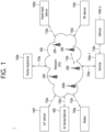
- FIG. 1 shows an example of a communication system to which implementations of the present disclosure is applied.
- the 5G usage scenarios shown in FIG. 1 are only exemplary, and the technical features of the present disclosure can be applied to other 5G usage scenarios which are not shown in FIG. 1 .
- Three main requirement categories for 5G include (1) a category of enhanced mobile broadband (eMBB), (2) a category of massive machine type communication (mMTC), and (3) a category of ultra-reliable and low latency communications (URLLC).
- eMBB enhanced mobile broadband
- mMTC massive machine type communication
- URLLC ultra-reliable and low latency communications
- the communication system 1 includes wireless devices 100a to 100f, base stations (BSs) 200, and a network 300.
- FIG. 1 illustrates a 5G network as an example of the network of the communication system 1, the implementations of the present disclosure are not limited to the 5G system, and can be applied to the future communication system beyond the 5G system.
- the BSs 200 and the network 300 may be implemented as wireless devices and a specific wireless device may operate as a BS/network node with respect to other wireless devices.
- the wireless devices 100a to 100f represent devices performing communication using radio access technology (RAT) (e.g., 5G new RAT (NR)) or LTE) and may be referred to as communication/radio/5G devices.
- RAT radio access technology
- the wireless devices 100a to 100f may include, without being limited to, a robot 100a, vehicles 100b-1 and 100b-2, an extended reality (XR) device 100c, a hand-held device 100d, a home appliance 100e, an IoT device 100f, and an artificial intelligence (AI) device/server 400.
- the vehicles may include a vehicle having a wireless communication function, an autonomous driving vehicle, and a vehicle capable of performing communication between vehicles.
- the vehicles may include an unmanned aerial vehicle (UAV) (e.g., a drone).
- UAV unmanned aerial vehicle
- the XR device may include an AR/VR/Mixed Reality (MR) device and may be implemented in the form of a head-mounted device (HMD), a head-up display (HUD) mounted in a vehicle, a television, a smartphone, a computer, a wearable device, a home appliance device, a digital signage, a vehicle, a robot, etc.
- the hand-held device may include a smartphone, a smartpad, a wearable device (e.g., a smartwatch or a smartglasses), and a computer (e.g., a notebook).
- the home appliance may include a TV, a refrigerator, and a washing machine.
- the IoT device may include a sensor and a smartmeter.
- the wireless devices 100a to 100f may be called user equipments (UEs).
- a UE may include, for example, a cellular phone, a smartphone, a laptop computer, a digital broadcast terminal, a personal digital assistant (PDA), a portable multimedia player (PMP), a navigation system, a slate personal computer (PC), a tablet PC, an ultrabook, a vehicle, a vehicle having an autonomous traveling function, a connected car, an UAV, an AI module, a robot, an AR device, a VR device, an MR device, a hologram device, a public safety device, an MTC device, an IoT device, a medical device, a FinTech device (or a financial device), a security device, a weather/environment device, a device related to a 5G service, or a device related to a fourth industrial revolution field.
- PDA personal digital assistant
- PMP portable multimedia player
- PC slate personal computer
- tablet PC a tablet PC
- ultrabook a vehicle, a vehicle having an autonomous
- the UAV may be, for example, an aircraft aviated by a wireless control signal without a human being onboard.
- the VR device may include, for example, a device for implementing an object or a background of the virtual world.
- the AR device may include, for example, a device implemented by connecting an object or a background of the virtual world to an object or a background of the real world.
- the MR device may include, for example, a device implemented by merging an object or a background of the virtual world into an object or a background of the real world.
- the hologram device may include, for example, a device for implementing a stereoscopic image of 360 degrees by recording and reproducing stereoscopic information, using an interference phenomenon of light generated when two laser lights called holography meet.
- the public safety device may include, for example, an image relay device or an image device that is wearable on the body of a user.
- the MTC device and the IoT device may be, for example, devices that do not require direct human intervention or manipulation.
- the MTC device and the IoT device may include smartmeters, vending machines, thermometers, smartbulbs, door locks, or various sensors.
- the medical device may be, for example, a device used for the purpose of diagnosing, treating, relieving, curing, or preventing disease.
- the medical device may be a device used for the purpose of diagnosing, treating, relieving, or correcting injury or impairment.
- the medical device may be a device used for the purpose of inspecting, replacing, or modifying a structure or a function.
- the medical device may be a device used for the purpose of adjusting pregnancy.
- the medical device may include a device for treatment, a device for operation, a device for (in vitro) diagnosis, a hearing aid, or a device for procedure.
- the security device may be, for example, a device installed to prevent a danger that may arise and to maintain safety.
- the security device may be a camera, a closed-circuit TV (CCTV), a recorder, or a black box.
- CCTV closed-circuit TV
- the FinTech device may be, for example, a device capable of providing a financial service such as mobile payment.
- the FinTech device may include a payment device or a point of sales (POS) system.
- POS point of sales
- the weather/environment device may include, for example, a device for monitoring or predicting a weather/environment.
- the wireless devices 100a to 100f may be connected to the network 300 via the BSs 200.
- An AI technology may be applied to the wireless devices 100a to 100f and the wireless devices 100a to 100f may be connected to the AI server 400 via the network 300.
- the network 300 may be configured using a 3G network, a 4G (e.g., LTE) network, a 5G (e.g., NR) network, and a beyond-5G network.
- the wireless devices 100a to 100f may communicate with each other through the BSs 200/network 300, the wireless devices 100a to 100f may perform direct communication (e.g., sidelink communication) with each other without passing through the BSs 200/network 300.
- the vehicles 100b-1 and 100b-2 may perform direct communication (e.g., vehicle-to-vehicle (V2V)/vehicle-to-everything (V2X) communication).
- the IoT device e.g., a sensor
- the IoT device may perform direct communication with other IoT devices (e.g., sensors) or other wireless devices 100a to 100f.
- Wireless communication/connections 150a, 150b and 150c may be established between the wireless devices 100a to 100f and/or between wireless device 100a to 100f and BS 200 and/or between BSs 200.
- the wireless communication/connections may be established through various RATs (e.g., 5G NR) such as uplink/downlink communication 150a, sidelink communication (or device-to-device (D2D) communication) 150b, inter-base station communication 150c (e.g., relay, integrated access and backhaul (IAB)), etc.
- the wireless devices 100a to 100f and the BSs 200/the wireless devices 100a to 100f may transmit/receive radio signals to/from each other through the wireless communication/connections 150a, 150b and 150c.
- the wireless communication/connections 150a, 150b and 150c may transmit/receive signals through various physical channels.
- various configuration information configuring processes e.g., channel encoding/decoding, modulation/demodulation, and resource mapping/de-mapping
- resource allocating processes for transmitting/receiving radio signals, may be performed based on the various proposals of the present disclosure.
- AI refers to the field of studying artificial intelligence or the methodology that can create it
- machine learning refers to the field of defining various problems addressed in the field of AI and the field of methodology to solve them.
- Machine learning is also defined as an algorithm that increases the performance of a task through steady experience on a task.
- Robot means a machine that automatically processes or operates a given task by its own ability.
- robots with the ability to recognize the environment and make self-determination to perform actions can be called intelligent robots.
- Robots can be classified as industrial, medical, home, military, etc., depending on the purpose or area of use.
- the robot can perform a variety of physical operations, such as moving the robot joints with actuators or motors.
- the movable robot also includes wheels, brakes, propellers, etc., on the drive, allowing it to drive on the ground or fly in the air.
- Autonomous driving means a technology that drives on its own, and autonomous vehicles mean vehicles that drive without user's control or with minimal user's control.
- autonomous driving may include maintaining lanes in motion, automatically adjusting speed such as adaptive cruise control, automatic driving along a set route, and automatically setting a route when a destination is set.
- the vehicle covers vehicles equipped with internal combustion engines, hybrid vehicles equipped with internal combustion engines and electric motors, and electric vehicles equipped with electric motors, and may include trains, motorcycles, etc., as well as cars.
- Autonomous vehicles can be seen as robots with autonomous driving functions.
- VR technology provides objects and backgrounds of real world only through computer graphic (CG) images.
- AR technology provides a virtual CG image on top of a real object image.
- MR technology is a CG technology that combines and combines virtual objects into the real world.
- MR technology is similar to AR technology in that they show real and virtual objects together. However, there is a difference in that in AR technology, virtual objects are used as complementary forms to real objects, while in MR technology, virtual objects and real objects are used as equal personalities.
- NR supports multiples numerologies (and/or multiple subcarrier spacings (SCS)) to support various 5G services. For example, if SCS is 15 kHz, wide area can be supported in traditional cellular bands, and if SCS is 30 kHz/60 kHz, dense-urban, lower latency, and wider carrier bandwidth can be supported. If SCS is 60 kHz or higher, bandwidths greater than 24.25 GHz can be supported to overcome phase noise.
- numerologies and/or multiple subcarrier spacings (SCS)
- the NR frequency band may be defined as two types of frequency range, i.e., FR1 and FR2.
- the numerical value of the frequency range may be changed.
- the frequency ranges of the two types may be as shown in Table 1 below.
- FR1 may mean "sub 6 GHz range”
- FR2 may mean "above 6 GHz range”
- mmW millimeter wave
- FR1 may include a frequency band of 410MHz to 7125MHz as shown in Table 2 below. That is, FR1 may include a frequency band of 6GHz (or 5850, 5900, 5925 MHz, etc.) or more. For example, a frequency band of 6 GHz (or 5850, 5900, 5925 MHz, etc.) or more included in FR1 may include an unlicensed band. Unlicensed bands may be used for a variety of purposes, for example for communication for vehicles (e.g., autonomous driving). [Table 2] Frequency Range designation Corresponding frequency range Subcarrier Spacing FR1 410MHz - 7125MHz 15, 30, 60kHz FR2 24250MHz - 52600MHz 60, 120, 240kHz
- the radio communication technologies implemented in the wireless devices in the present disclosure may include narrowband internet-of-things (NB-IoT) technology for low-power communication as well as LTE, NR and 6G.
- NB-IoT technology may be an example of low power wide area network (LPWAN) technology, may be implemented in specifications such as LTE Cat NB1 and/or LTE Cat NB2, and may not be limited to the above-mentioned names.
- LPWAN low power wide area network
- the radio communication technologies implemented in the wireless devices in the present disclosure may communicate based on LTE-M technology.
- LTE-M technology may be an example of LPWAN technology and be called by various names such as enhanced machine type communication (eMTC).
- eMTC enhanced machine type communication
- LTE-M technology may be implemented in at least one of the various specifications, such as 1) LTE Cat 0, 2) LTE Cat M1, 3) LTE Cat M2, 4) LTE non-bandwidth limited (non-BL), 5) LTE-MTC, 6) LTE Machine Type Communication, and/or 7) LTE M, and may not be limited to the above-mentioned names.
- the radio communication technologies implemented in the wireless devices in the present disclosure may include at least one of ZigBee, Bluetooth, and/or LPWAN which take into account low-power communication, and may not be limited to the above-mentioned names.
- ZigBee technology may generate personal area networks (PANs) associated with small/low-power digital communication based on various specifications such as IEEE 802.15.4 and may be called various names.
- PANs personal area networks
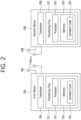
- FIG. 2 shows an example of wireless devices to which implementations of the present disclosure is applied.
- a first wireless device 100 and a second wireless device 200 may transmit/receive radio signals to/from an external device through a variety of RATs (e.g., LTE and NR).
- RATs e.g., LTE and NR
- ⁇ the first wireless device 100 and the second wireless device 200 ⁇ may correspond to at least one of ⁇ the wireless device 100a to 100f and the BS 200 ⁇ , ⁇ the wireless device 100a to 100f and the wireless device 100a to 100f ⁇ and/or ⁇ the BS 200 and the BS 200 ⁇ of FIG. 1 .
- the first wireless device 100 may include at least one transceiver, such as a transceiver 106, at least one processing chip, such as a processing chip 101, and/or one or more antennas 108.
- a transceiver such as a transceiver 106
- a processing chip such as a processing chip 101
- antennas 108 one or more antennas 108.
- the processing chip 101 may include at least one processor, such a processor 102, and at least one memory, such as a memory 104. It is exemplarily shown in FIG. 2 that the memory 104 is included in the processing chip 101. Additional and/or alternatively, the memory 104 may be placed outside of the processing chip 101.
- the processor 102 may control the memory 104 and/or the transceiver 106 and may be adapted to implement the descriptions, functions, procedures, suggestions, methods and/or operational flowcharts described in the present disclosure. For example, the processor 102 may process information within the memory 104 to generate first information/signals and then transmit radio signals including the first information/signals through the transceiver 106. The processor 102 may receive radio signals including second information/signals through the transceiver 106 and then store information obtained by processing the second information/signals in the memory 104.
- the memory 104 may be operably connectable to the processor 102.
- the memory 104 may store various types of information and/or instructions.
- the memory 104 may store a software code 105 which implements instructions that, when executed by the processor 102, perform the descriptions, functions, procedures, suggestions, methods and/or operational flowcharts disclosed in the present disclosure.
- the software code 105 may implement instructions that, when executed by the processor 102, perform the descriptions, functions, procedures, suggestions, methods and/or operational flowcharts disclosed in the present disclosure.
- the software code 105 may control the processor 102 to perform one or more protocols.
- the software code 105 may control the processor 102 to perform one or more layers of the radio interface protocol.
- the processor 102 and the memory 104 may be a part of a communication modem/circuit/chip designed to implement RAT (e.g., LTE or NR).
- the transceiver 106 may be connected to the processor 102 and transmit and/or receive radio signals through one or more antennas 108.
- Each of the transceiver 106 may include a transmitter and/or a receiver.
- the transceiver 106 may be interchangeably used with radio frequency (RF) unit(s).
- the first wireless device 100 may represent a communication modem/circuit/chip.
- the second wireless device 200 may include at least one transceiver, such as a transceiver 206, at least one processing chip, such as a processing chip 201, and/or one or more antennas 208.
- the processing chip 201 may include at least one processor, such a processor 202, and at least one memory, such as a memory 204. It is exemplarily shown in FIG. 2 that the memory 204 is included in the processing chip 201. Additional and/or alternatively, the memory 204 may be placed outside of the processing chip 201.
- the processor 202 may control the memory 204 and/or the transceiver 206 and may be adapted to implement the descriptions, functions, procedures, suggestions, methods and/or operational flowcharts described in the present disclosure. For example, the processor 202 may process information within the memory 204 to generate third information/signals and then transmit radio signals including the third information/signals through the transceiver 206. The processor 202 may receive radio signals including fourth information/signals through the transceiver 106 and then store information obtained by processing the fourth information/signals in the memory 204.
- the memory 204 may be operably connectable to the processor 202.
- the memory 204 may store various types of information and/or instructions.
- the memory 204 may store a software code 205 which implements instructions that, when executed by the processor 202, perform the descriptions, functions, procedures, suggestions, methods and/or operational flowcharts disclosed in the present disclosure.
- the software code 205 may implement instructions that, when executed by the processor 202, perform the descriptions, functions, procedures, suggestions, methods and/or operational flowcharts disclosed in the present disclosure.
- the software code 205 may control the processor 202 to perform one or more protocols.
- the software code 205 may control the processor 202 to perform one or more layers of the radio interface protocol.
- the processor 202 and the memory 204 may be a part of a communication modem/circuit/chip designed to implement RAT (e.g., LTE or NR).
- the transceiver 206 may be connected to the processor 202 and transmit and/or receive radio signals through one or more antennas 208.
- Each of the transceiver 206 may include a transmitter and/or a receiver.
- the transceiver 206 may be interchangeably used with RF unit.
- the second wireless device 200 may represent a communication modem/circuit/chip.
- One or more protocol layers may be implemented by, without being limited to, one or more processors 102 and 202.
- the one or more processors 102 and 202 may implement one or more layers (e.g., functional layers such as physical (PHY) layer, media access control (MAC) layer, radio link control (RLC) layer, packet data convergence protocol (PDCP) layer, radio resource control (RRC) layer, and service data adaptation protocol (SDAP) layer).
- layers e.g., functional layers such as physical (PHY) layer, media access control (MAC) layer, radio link control (RLC) layer, packet data convergence protocol (PDCP) layer, radio resource control (RRC) layer, and service data adaptation protocol (SDAP) layer).
- PHY physical
- MAC media access control
- RLC radio link control
- PDCP packet data convergence protocol
- RRC radio resource control
- SDAP service data adaptation protocol
- the one or more processors 102 and 202 may generate one or more protocol data units (PDUs) and/or one or more service data unit (SDUs) according to the descriptions, functions, procedures, suggestions, methods and/or operational flowcharts disclosed in the present disclosure.
- the one or more processors 102 and 202 may generate messages, control information, data, or information according to the descriptions, functions, procedures, suggestions, methods and/or operational flowcharts disclosed in the present disclosure.
- the one or more processors 102 and 202 may generate signals (e.g., baseband signals) including PDUs, SDUs, messages, control information, data, or information according to the descriptions, functions, procedures, suggestions, methods and/or operational flowcharts disclosed in the present disclosure and provide the generated signals to the one or more transceivers 106 and 206.
- the one or more processors 102 and 202 may receive the signals (e.g., baseband signals) from the one or more transceivers 106 and 206 and acquire the PDUs, SDUs, messages, control information, data, or information according to the descriptions, functions, procedures, suggestions, methods and/or operational flowcharts disclosed in the present disclosure.
- the one or more processors 102 and 202 may be referred to as controllers, microcontrollers, microprocessors, or microcomputers.
- the one or more processors 102 and 202 may be implemented by hardware, firmware, software, or a combination thereof.
- ASICs application specific integrated circuits
- DSPs digital signal processors
- DSPDs digital signal processing devices
- PLDs programmable logic devices
- FPGAs field programmable gate arrays
- the descriptions, functions, procedures, suggestions, methods and/or operational flowcharts disclosed in the present disclosure may be implemented using firmware or software and the firmware or software may be adapted to include the modules, procedures, or functions.
- Firmware or software adapted to perform the descriptions, functions, procedures, suggestions, methods and/or operational flowcharts disclosed in the present disclosure may be included in the one or more processors 102 and 202 or stored in the one or more memories 104 and 204 so as to be driven by the one or more processors 102 and 202.
- the descriptions, functions, procedures, suggestions, methods and/or operational flowcharts disclosed in the present disclosure may be implemented using firmware or software in the form of code, commands, and/or a set of commands.
- the one or more memories 104 and 204 may be connected to the one or more processors 102 and 202 and store various types of data, signals, messages, information, programs, code, instructions, and/or commands.
- the one or more memories 104 and 204 may be configured by read-only memories (ROMs), random access memories (RAMs), electrically erasable programmable read-only memories (EPROMs), flash memories, hard drives, registers, cash memories, computer-readable storage media, and/or combinations thereof.
- the one or more memories 104 and 204 may be located at the interior and/or exterior of the one or more processors 102 and 202.
- the one or more memories 104 and 204 may be connected to the one or more processors 102 and 202 through various technologies such as wired or wireless connection.
- the one or more transceivers 106 and 206 may transmit user data, control information, and/or radio signals/channels, mentioned in the descriptions, functions, procedures, suggestions, methods and/or operational flowcharts disclosed in the present disclosure, to one or more other devices.
- the one or more transceivers 106 and 206 may receive user data, control information, and/or radio signals/channels, mentioned in the descriptions, functions, procedures, suggestions, methods and/or operational flowcharts disclosed in the present disclosure, from one or more other devices.
- the one or more transceivers 106 and 206 may be connected to the one or more processors 102 and 202 and transmit and receive radio signals.
- the one or more processors 102 and 202 may perform control so that the one or more transceivers 106 and 206 may transmit user data, control information, or radio signals to one or more other devices.
- the one or more processors 102 and 202 may perform control so that the one or more transceivers 106 and 206 may receive user data, control information, or radio signals from one or more other devices.
- the one or more transceivers 106 and 206 may be connected to the one or more antennas 108 and 208 and the one or more transceivers 106 and 206 may be adapted to transmit and receive user data, control information, and/or radio signals/channels, mentioned in the descriptions, functions, procedures, suggestions, methods and/or operational flowcharts disclosed in the present disclosure, through the one or more antennas 108 and 208.
- the one or more antennas 108 and 208 may be a plurality of physical antennas or a plurality of logical antennas (e.g., antenna ports).
- the one or more transceivers 106 and 206 may convert received user data, control information, radio signals/channels, etc., from RF band signals into baseband signals in order to process received user data, control information, radio signals/channels, etc., using the one or more processors 102 and 202.
- the one or more transceivers 106 and 206 may convert the user data, control information, radio signals/channels, etc., processed using the one or more processors 102 and 202 from the base band signals into the RF band signals.
- the one or more transceivers 106 and 206 may include (analog) oscillators and/or filters.
- the one or more transceivers 106 and 206 can up-convert OFDM baseband signals to OFDM signals by their (analog) oscillators and/or filters under the control of the one or more processors 102 and 202 and transmit the up-converted OFDM signals at the carrier frequency.
- the one or more transceivers 106 and 206 may receive OFDM signals at a carrier frequency and down-convert the OFDM signals into OFDM baseband signals by their (analog) oscillators and/or filters under the control of the one or more processors 102 and 202.
- a UE may operate as a transmitting device in uplink (UL) and as a receiving device in downlink (DL).
- a BS may operate as a receiving device in UL and as a transmitting device in DL.
- the first wireless device 100 acts as the UE
- the second wireless device 200 acts as the BS.
- the processor(s) 102 connected to, mounted on or launched in the first wireless device 100 may be adapted to perform the UE behavior according to an implementation of the present disclosure or control the transceiver(s) 106 to perform the UE behavior according to an implementation of the present disclosure.
- the processor(s) 202 connected to, mounted on or launched in the second wireless device 200 may be adapted to perform the BS behavior according to an implementation of the present disclosure or control the transceiver(s) 206 to perform the BS behavior according to an implementation of the present disclosure.
- a BS is also referred to as a node B (NB), an eNode B (eNB), or a gNB
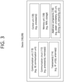
- FIG. 3 shows an example of a wireless device to which implementations of the present disclosure is applied.
- the wireless device may be implemented in various forms according to a use-case/service (refer to FIG. 1 ).
- wireless devices 100 and 200 may correspond to the wireless devices 100 and 200 of FIG. 2 and may be configured by various elements, components, units/portions, and/or modules.
- each of the wireless devices 100 and 200 may include a communication unit 110, a control unit 120, a memory unit 130, and additional components 140.
- the communication unit 110 may include a communication circuit 112 and transceiver(s) 114.
- the communication circuit 112 may include the one or more processors 102 and 202 of FIG. 2 and/or the one or more memories 104 and 204 of FIG. 2 .
- the transceiver(s) 114 may include the one or more transceivers 106 and 206 of FIG.
- the control unit 120 is electrically connected to the communication unit 110, the memory unit 130, and the additional components 140 and controls overall operation of each of the wireless devices 100 and 200.
- the control unit 120 may control an electric/mechanical operation of each of the wireless devices 100 and 200 based on programs/code/commands/information stored in the memory unit 130.
- the control unit 120 may transmit the information stored in the memory unit 130 to the exterior (e.g., other communication devices) via the communication unit 110 through a wireless/wired interface or store, in the memory unit 130, information received through the wireless/wired interface from the exterior (e.g., other communication devices) via the communication unit 110.
- the additional components 140 may be variously configured according to types of the wireless devices 100 and 200.
- the additional components 140 may include at least one of a power unit/battery, input/output (I/O) unit (e.g., audio I/O port, video I/O port), a driving unit, and a computing unit.
- the wireless devices 100 and 200 may be implemented in the form of, without being limited to, the robot (100a of FIG. 1 ), the vehicles (100b-1 and 100b-2 of FIG. 1 ), the XR device (100c of FIG. 1 ), the hand-held device (100d of FIG. 1 ), the home appliance (100e of FIG. 1 ), the IoT device (100f of FIG.
- the wireless devices 100 and 200 may be used in a mobile or fixed place according to a use-example/service.
- the entirety of the various elements, components, units/portions, and/or modules in the wireless devices 100 and 200 may be connected to each other through a wired interface or at least a part thereof may be wirelessly connected through the communication unit 110.
- the control unit 120 and the communication unit 110 may be connected by wire and the control unit 120 and first units (e.g., 130 and 140) may be wirelessly connected through the communication unit 110.
- Each element, component, unit/portion, and/or module within the wireless devices 100 and 200 may further include one or more elements.
- the control unit 120 may be configured by a set of one or more processors.
- control unit 120 may be configured by a set of a communication control processor, an application processor (AP), an electronic control unit (ECU), a graphical processing unit, and a memory control processor.
- memory unit 130 may be configured by a RAM, a DRAM, a ROM, a flash memory, a volatile memory, a non-volatile memory, and/or a combination thereof.
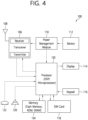
- FIG. 4 shows an example of UE to which implementations of the present disclosure is applied.
- a UE 100 may correspond to the first wireless device 100 of FIG. 2 and/or the wireless device 100 or 200 of FIG. 3 .
- a UE 100 includes a processor 102, a memory 104, a transceiver 106, one or more antennas 108, a power management module 110, a battery 112, a display 114, a keypad 116, a subscriber identification module (SIM) card 118, a speaker 120, and a microphone 122.
- SIM subscriber identification module
- the processor 102 may be adapted to implement the descriptions, functions, procedures, suggestions, methods and/or operational flowcharts disclosed in the present disclosure.
- the processor 102 may be adapted to control one or more other components of the UE 100 to implement the descriptions, functions, procedures, suggestions, methods and/or operational flowcharts disclosed in the present disclosure.
- Layers of the radio interface protocol may be implemented in the processor 102.
- the processor 102 may include ASIC, other chipset, logic circuit and/or data processing device.
- the processor 102 may be an application processor.
- the processor 102 may include at least one of a digital signal processor (DSP), a central processing unit (CPU), a graphics processing unit (GPU), a modem (modulator and demodulator).
- DSP digital signal processor
- CPU central processing unit
- GPU graphics processing unit
- modem modulator and demodulator
- processor 102 may be found in SNAPDRAGON TM series of processors made by Qualcomm ® , EXYNOS TM series of processors made by Samsung ® , A series of processors made by Apple ® , HELIO TM series of processors made by MediaTek ® , ATOM TM series of processors made by Intel ® or a corresponding next generation processor.
- the memory 104 is operatively coupled with the processor 102 and stores a variety of information to operate the processor 102.
- the memory 104 may include ROM, RAM, flash memory, memory card, storage medium and/or other storage device.
- modules e.g., procedures, functions, etc.
- the modules can be stored in the memory 104 and executed by the processor 102.
- the memory 104 can be implemented within the processor 102 or external to the processor 102 in which case those can be communicatively coupled to the processor 102 via various means as is known in the art.
- the transceiver 106 is operatively coupled with the processor 102, and transmits and/or receives a radio signal.
- the transceiver 106 includes a transmitter and a receiver.
- the transceiver 106 may include baseband circuitry to process radio frequency signals.
- the transceiver 106 controls the one or more antennas 108 to transmit and/or receive a radio signal.
- the power management module 110 manages power for the processor 102 and/or the transceiver 106.
- the battery 112 supplies power to the power management module 110.
- the display 114 outputs results processed by the processor 102.
- the keypad 116 receives inputs to be used by the processor 102.
- the keypad 116 may be shown on the display 114.
- the SIM card 118 is an integrated circuit that is intended to securely store the international mobile subscriber identity (IMSI) number and its related key, which are used to identify and authenticate subscribers on mobile telephony devices (such as mobile phones and computers). It is also possible to store contact information on many SIM cards.
- IMSI international mobile subscriber identity
- the speaker 120 outputs sound-related results processed by the processor 102.
- the microphone 122 receives sound-related inputs to be used by the processor 102.
- FIG. 5 shows an example of an overall architecture of an NG-RAN to which implementations of the present disclosure is applied.
- a Next Generation (NG)-Radio Access Network consists of a set of gNBs connected to the 5GC through the NG interface.
- the NG-RAN may consist of a set of ng-eNBs
- the ng-eNB may consist of an ng-eNB-CU and one or more ng-eNB-DUs.
- the ng-eNB-CU and the ng-eNB-DU are connected through the W1 interface.
- the general principles for the overall architecture of the NG-RAN described below also apply to the ng-eNB and W1 interfaces, unless explicitly specified otherwise.
- gNBs can be interconnected through the Xn interface.
- a gNB may consist of a gNB Central Unit (gNB-CU) and one or more gNB Distributed Unit (gNB-DU).
- gNB-CU and a gNB-DU is connected via F1 interface.
- gNB-CU may be simply denoted as CU and gNB-DU as DU.
- the gNB-CU is a logical node hosting RRC, SDAP and PDCP protocols of the gNB or RRC and PDCP protocols of the en-gNB that controls the operation of one or more gNB-DUs.
- the gNB-CU terminates the F1 interface connected with the gNB-DU.
- a gNB-DU is a logical node hosting RLC, MAC and PHY layers of the gNB or en-gNB, and its operation is partly controlled by gNB-CU.
- One gNB-DU supports one or multiple cells.
- One cell is supported by only one gNB-DU.
- the gNB-DU terminates the F1 interface connected with the gNB-CU.
- One gNB-DU may be connected to only one gNB-CU.
- a gNB-DU may be connected to multiple gNB-CUs by appropriate implementation.
- NG, Xn and F1 are logical interfaces.
- the NG and Xn-C interfaces for a gNB consisting of a gNB-CU and gNB-DUs, terminate in the gNB-CU.
- E-UTRAN-NR Dual Connectivity EN-DC
- the S1-U and X2-C interfaces for a gNB consisting of a gNB-CU and gNB-DUs terminate in the gNB-CU.
- the gNB-CU and connected gNB-DUs are only visible to other gNBs and the 5GC as a gNB.
- FIG. 6 shows an example of an overall architecture for separation of gNB-CU-CP and gNB-CU-UP to which implementations of the present disclosure is applied.
- a gNB may consist of a gNB-CU Control Plane (gNB-CU-CP), multiple gNB-CU User Planes (gNB-CU-UPs), and multiple gNB-DUs.
- gNB-CU-CP may be simply denoted as CU-CP and gNB-CU-UP as CU-UP.
- the gNB-CU-CP is a logical node hosting the RRC and the control plane part of the PDCP protocol of the gNB-CU for an en-gNB or a gNB.
- the gNB-CU-CP terminates the E1 interface connected with the gNB-CU-UP and the F1-C interface connected with the gNB-DU.
- the gNB-CU-UP is a logical node hosting the user plane part of the PDCP protocol of the gNB-CU for an en-gNB, and the user plane part of the PDCP protocol and the SDAP protocol of the gNB-CU for a gNB.
- the gNB-CU-UP terminates the E1 interface connected with the gNB-CU-CP and the F1-U interface connected with the gNB-D.
- the gNB-CU-CP is connected to the gNB-DU through the F1-C interface.
- the gNB-CU-UP is connected to the gNB-DU through the F1-U interface.
- the gNB-CU-UP is connected to the gNB-CU-CP through the E1 interface.
- One gNB-DU is connected to only one gNB-CU-CP.
- One gNB-CU-UP may be connected to only one gNB-CU-CP.
- a gNB-DU and/or a gNB-CU-UP may be connected to multiple gNB-CU-CPs by appropriate implementation.
- One gNB-DU may be connected to multiple gNB-CU-UPs under the control of the same gNB-CU-CP.
- One gNB-CU-UP may be connected to multiple DUs under the control of the same gNB-CU-CP;
- the connectivity between a gNB-CU-UP and a gNB-DU may be established by the gNB-CU-CP using Bearer Context Management functions.
- the gNB-CU-CP may select the appropriate gNB-CU-UP(s) for the requested services for the UE. In case of multiple CU-Ups, they belong to same security domain.
- Data forwarding between gNB-CU-UPs during intra-gNB-CU-CP handover within a gNB may be supported by Xn-U.
- FIG. 7 shows an example of 5G system architecture to which implementations of the present disclosure is applied.
- the 5G system (5GS) architecture consists of the following network functions (NF).
- FIG. 7 depicts the 5G system architecture in the non-roaming case, using the reference point representation showing how various network functions interact with each other.
- the UDSF, NEF and NRF have not been depicted. However, all depicted Network Functions can interact with the UDSF, UDR, NEF and NRF as necessary.
- the UDR and its connections with other NFs are not depicted in FIG. 7 .
- the NWDAF and its connections with other NFs are not depicted in FIG. 7 .
- the 5G system architecture contains the following reference points:
- a couple of NFs may need to be associated with each other to serve a UE.
- An RRC state indicates whether an RRC layer of the UE is logically connected to an RRC layer of the network.
- RRCCONNECTED when the RRC connection is established between the RRC layer of the UE and the RRC layer of the E-UTRAN, the UE is in the RRC connected state (RRCCONNECTED). Otherwise, the UE is in the RRC idle state (RRC IDLE).
- RRC_INACTIVE the RRC inactive state
- RRC_lNACTIVE may be used for various purposes.
- MMTC massive machine type communications
- a predetermined operation may be performed according to the RRC state.
- RRC _IDLE Public Land Mobile Network (PLMN) selection, broadcast of System Information (SI), cell re-selection mobility, Core Network (CN) paging and Discontinuous Reception (DRX) configured by Non-Access Stratum (NAS) may be performed.
- PLMN Public Land Mobile Network
- SI System Information
- CN Core Network
- DRX Discontinuous Reception
- NAS Non-Access Stratum
- the UE shall have been allocated an Identifier (ID) which uniquely identifies the UE in a tracking area. No RRC context stored in the BS.
- the UE has an RRC connection with the network (i.e., E-UTRAN/NG-RAN).
- Network-CN connection (both C/U-planes) is also established for UE.
- the UE AS context is stored in the network and the UE.
- the RAN knows the cell which the UE belongs to.
- the network can transmit and/or receive data to/from UE.
- Network controlled mobility including measurement is also performed.
- RRC_IDLE Most of operations performed in RRC_IDLE may be performed in RRC_INACTIVE. But, instead of CN paging in RRC _IDLE, RAN paging is performed in RRC _INACTIVE. In other words, in RRC _IDLE, paging for Mobile Terminated (MT) data is initiated by core network and paging area is managed by core network. In RRC _INACTIVE, paging is initiated by NG-RAN, and RAN-based Notification Area (RNA) is managed by NG-RAN. Further, instead of DRX for CN paging configured by NAS in RRC IDLE, DRX for RAN paging is configured by NG-RAN in RRC INACTIVE.
- DRX for CN paging configured by NAS in RRC IDLE
- DRX for RAN paging is configured by NG-RAN in RRC INACTIVE.
- 5GC-NG-RAN connection (both C/U-planes) is established for UE, and the UE AS context is stored in NG-RAN and the UE.
- NG-RAN knows the RNA which the UE belongs to.
- SDT Small Data Transmission
- SDT is a procedure allowing data transmission while remaining in RRC_INACTIVE state (i.e., without transitioning to RRC _CONNECTED state).
- SDT may be enabled on a radio bearer basis and may be initiated by the UE only if i) less than a configured amount of UL data awaits transmission across all radio bearers for which SDT is enabled, ii) the DL Reference Signal Received Power (RSRP) is above a configured threshold, and iii) a valid SDT resource is available.
- RSRP DL Reference Signal Received Power
- SDT procedure may be initiated with either a transmission over RACH (configured via system information) or over Type 1 Configured Gant (CG) resources (configured via dedicated signaling in RRC Release message).
- the SDT resources may be configured on initial Bandwidth Part (BWP) for both RACH and CG.
- RACH and CG resources for SDT may be configured on either or both of Normal UL (NUL) and Supplementary (SUL) carriers.
- NUL Normal UL
- SUL Supplementary
- the network may configure 2-step and/or 4-step RA resources for SDT. When both 2-step and 4-step RA resources for SDT are configured, the UE may select the RA type.
- Contention-Free Random Access (CFRA) is not supported for SDT over RACH.
- the SDT procedure may be terminated successfully after the UE is directed to RRC_IDLE or RRC INACTIVE (e.g., via RRC Release message) or to RRC _CONNECTED (e.g., via RRC Resume message), or unsuccessfully upon cell re-selection, expiry of the SDT failure detection timer, an RLC entity reaching a configured maximum retransmission threshold.
- RRC_IDLE Upon failure of the SDT procedure, the UE may transition to RRC_IDLE.
- PUSCH Physical Uplink Shared Channel
- SDT procedure over CG resources may only be initiated with valid UL timing alignment.
- the UL timing alignment may be maintained by the UE based on network configured SDT-specific timing alignment timer and DL RSRP of configured number of highest ranked Synchronization Signal Blocks (SSBs).
- SSBs Synchronization Signal Blocks
- Logical channel restrictions may be configured by the network for radio bearers enabled for SDT, and may be applied by the UE regardless of whether the SDT procedure is initiated with either a transmission over RACH or over Type 1 CG.
- FIG. 8 shows an example of an SDT procedure to which implementations of the present disclosure is applied.
- FIG. 8 illustrates an RA-based SDT procedure with UE context relocation. The operation of each step is described as follows.
- 3GPP NR Rel-18 it was decided to support Mobile Terminated MT)-SDT for DL data to be transmitted to UE. More specifically, from 3GPP NR Rel-18, it was decided to support DL data transmission through paging-triggered SDT.
- the gNB-CU-CP In order to support MT-SDT from 3GPP NR Rel-18, the gNB-CU-CP should be able to determine whether to transmit DL data through MT-SDT while maintaining the UE in the RRC_INACTIVE state or whether to transition the UE to the RRC_CONNECTED state. In order to determine this, the gNB-CU-CP needs to know the size of the DL data that has arrived at the gNB-CU-UP, but currently, the E1AP DL data notification message (DATA NOTIFICATION) transmitted by the gNB-CU-UP to the gNB-CU-CP does not include information about the size of DL data.
- DATA NOTIFICATION E1AP DL data notification message
- the last serving gNB that receives the XnAP Retrieve UE Context Request (RETRIEVE UE CONTEXT REQUEST) message from the new gNB may additionally perform a partial UE context transfer procedure. In this process, it may take a long time until the DL data is transmitted through the MT-SDT.
- RETRIEVE UE CONTEXT REQUEST XnAP Retrieve UE Context Request
- the new NG-RAN and the last serving NG-RAN may be replaced with the new gNB and the last serving gNB, respectively. Also, the new gNB may be replaced with the receiving gNB described in FIG. 8 .
- an existing RRC message may be used for an RRC message between the NG-RAN and the UE, or a new RRC message may be defined and used.
- An existing E1 message may be used for an E1 message between the gNB-CU-CP and the gNB-CU-UP, or a new E1 message may be defined and used.
- An existing F1 message may be used for an F1 message between the gNB-CU-CP and/or the gNB-CU-UP and the gNB-DU, or a new F1 message may be defined and used.
- An existing Xn message may be used for an Xn message between the gNB-CU of the receiving gNB and the gNB-CU of the last serving gNB, or a new Xn message may be defined and used.
- FIG. 9 shows an example of a method performed by a receiving gNB to which implementations of the present disclosure is applied.
- the method includes receiving a RAN paging message from a last serving gNB.
- the RAN paging message includes an MT-SDT indication informing that a MT- SDT is supported.
- step S910 the method includes transmitting a paging message to a UE.
- step S920 the method includes performing a random access procedure with the UE.
- step S930 the method includes receiving an RRC resume request message from the UE.
- the RRC resume request message includes an I-RNTI.
- the method includes transmitting a Retrieve UE Context Request message to the last serving gNB based on the I-RNTI.
- the Retrieve UE Context Request message includes information about a DL Transport Network Layer (TNL) address associated with the MT-SDT.
- TNL Transport Network Layer
- step S950 the method includes receiving DL data associated with the MT-SDT from the last serving gNB based on the DL TNL address.
- step S960 the method includes transmitting the DL data to the UE.
- the receiving gNB may include a gNB-CU and a gNB-DU
- the gNB-CU may include a gNB-CU-CP and a gNB-CU-UP.
- the receiving gNB may consist of a gNB-CU and one or more gNB-DUs
- the gNB-CU may consist of a gNB-CU-CP and one or more gNB-CU-UPs.
- the DL TNL address may be allocated by the gNB-DU and transmitted to the gNB-CU-CP.
- the DL TNL address may be transmitted to the gNB-CU-CP via an Initial UL RRC Message Transfer message.
- the Initial UL RRC Message Transfer message may include the RRC resume request message received from the UE.
- the Retrieve UE Context Request message including the DL TNL address may be transmitted by the gNB-CU-CP to the last serving gNB.
- the receiving gNB includes a gNB-CU and a gNB-DU
- the gNB-CU includes a gNB-CU-CP and a gNB-CU-UP
- the RAN paging message including the MT-SDT indication may be received by the gNB-CU-CP from the last serving gNB.
- the MT-SDT indication may be transmitted from the gNB-CU-CP to the gNB-DU.
- the MT-SDT indication may include a bearer ID associated with the MT-SDT.
- the method in perspective of the receiving gNB described above in FIG. 9 may be performed by the second wireless device 200 shown in FIG. 2 and/or the wireless device 200 shown in FIG. 3 .
- the receiving gNB comprises at least one transceiver, at least one processor, and at least one memory operably connectable to the at least one processor.
- the at least one memory stores instructions to cause the at least one processor to perform following operations. That is, the receiving gNB may perform the following operations.
- the receiving gNB receives a RAN paging message from a last serving gNB.
- the RAN paging message includes an MT-SDT indication informing that a MT- SDT is supported.
- the receiving gNB transmits a paging message to a UE.
- the receiving gNB performs a random access procedure with the UE.
- the receiving gNB receives an RRC resume request message from the UE.
- the RRC resume request message includes an I-RNTI.
- the receiving gNB transmits a Retrieve UE Context Request message to the last serving gNB based on the I-RNTI.
- the Retrieve UE Context Request message includes information about a DL TNL address associated with the MT-SDT.
- the receiving gNB receives DL data associated with the MT-SDT from the last serving gNB based on the DL TNL address.
- the receiving gNB transmits the DL data to the UE.
- the receiving gNB may include a gNB-CU and a gNB-DU
- the gNB-CU may include a gNB-CU-CP and a gNB-CU-UP.
- the receiving gNB may consist of a gNB-CU and one or more gNB-DUs
- the gNB-CU may consist of a gNB-CU-CP and one or more gNB-CU-UPs.
- the DL TNL address may be allocated by the gNB-DU and transmitted to the gNB-CU-CP.
- the DL TNL address may be transmitted to the gNB-CU-CP via an Initial UL RRC Message Transfer message.
- the Initial UL RRC Message Transfer message may include the RRC resume request message received from the UE.
- the Retrieve UE Context Request message including the DL TNL address may be transmitted by the gNB-CU-CP to the last serving gNB.
- the receiving gNB includes a gNB-CU and a gNB-DU
- the gNB-CU includes a gNB-CU-CP and a gNB-CU-UP
- the RAN paging message including the MT-SDT indication may be received by the gNB-CU-CP from the last serving gNB.
- the MT-SDT indication may be transmitted from the gNB-CU-CP to the gNB-DU.
- the MT-SDT indication may include a bearer ID associated with the MT-SDT.
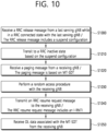
- FIG. 10 shows an example of a method performed by a UE to which implementations of the present disclosure is applied.
- step S1000 the method includes receiving an RRC release message from a last serving gNB while in an RRC connected state with the last serving gNB.
- the RRC release message includes a suspend configuration.
- step S1010 the method includes transitioning to an RRC inactive state based on the suspend configuration.
- step S1020 the method includes receiving a paging message from a receiving gNB.
- the paging message is based on MT- SDT.
- step S1030 the method includes performing a random access procedure with the receiving gNB.
- step S1040 the method includes transmitting an RRC resume request message to the receiving gNB.
- the RRC resume request message includes an I-RNTI.
- step S1050 the method includes receiving DL data associated with the MT-SDT from the receiving gNB.
- the method may further include, after receiving the DL data associated with the MT-SDT, receiving a second RRC release message including a suspend configuration from the receiving gNB. Based on receiving the second RRC release message, the UE may not transition to the RRC connected state and remain in the RRC inactive state.
- the RRC resume request message may include at least one of an RRC resume cause, an authentication token, and/or information related to the MT-SDT.
- the method may further include, after receiving the DL data associated with the MT-SDT, transmitting UL data to the receiving gNB.
- the receiving gNB may include a gNB-CU and a gNB-DU
- the gNB-CU may include a gNB-CU-CP and a gNB-CU-UP.
- the receiving gNB may consist of a gNB-CU and one or more gNB-DUs
- the gNB-CU may consist of a gNB-CU-CP and one or more gNB-CU-UPs.
- the paging message may be received from the gNB-DU of the receiving gNB.
- the random access procedure may be performed with the gNB-DU of the receiving gNB.
- the RRC resume request message may be transmitted to the gNB-DU of the receiving gNB.
- the DL data may be received from the gNB-DU of the receiving gNB.
- the UE may communicate with at least one of a mobile device, a network and/or an autonomous vehicle other than the UE.
- the method in perspective of the UE described above in FIG. 10 may be performed by the first wireless device 100 shown in FIG. 2 , the wireless device 100 shown in FIG. 3 , and/or the UE 100 shown in FIG. 4 .
- the UE comprises at least one transceiver, at least one processor, and at least one memory operably connectable to the at least one processor.
- the at least one memory stores instructions to cause the at least one processor to perform following operations. That is, the UE may perform the following operations.
- the UE receives an RRC release message from a last serving gNB while in an RRC connected state with the last serving gNB.
- the RRC release message includes a suspend configuration.
- the UE transitions to an RRC inactive state based on the suspend configuration.
- the UE receives a paging message from a receiving gNB.
- the paging message is based on MT- SDT.
- the UE performs a random access procedure with the receiving gNB.
- the UE transmit an RRC resume request message to the receiving gNB.
- the RRC resume request message includes an I-RNTI.
- the UE receives DL data associated with the MT-SDT from the receiving gNB.
- the UE may receive a second RRC release message including a suspend configuration from the receiving gNB. Based on receiving the second RRC release message, the UE may not transition to the RRC connected state and remain in the RRC inactive state.
- the RRC resume request message may include at least one of an RRC resume cause, an authentication token, and/or information related to the MT-SDT.
- the UE may transmit UL data to the receiving gNB.
- the receiving gNB may include a gNB-CU and a gNB-DU
- the gNB-CU may include a gNB-CU-CP and a gNB-CU-UP.
- the receiving gNB may consist of a gNB-CU and one or more gNB-DUs
- the gNB-CU may consist of a gNB-CU-CP and one or more gNB-CU-UPs.
- the paging message may be received from the gNB-DU of the receiving gNB.
- the random access procedure may be performed with the gNB-DU of the receiving gNB.
- the RRC resume request message may be transmitted to the gNB-DU of the receiving gNB.
- the DL data may be received from the gNB-DU of the receiving gNB.
- the method in perspective of the UE described above in FIG. 10 may be performed by control of the processor 102 included in the first wireless device 100 shown in FIG. 2 , by control of the communication unit 110 and/or the control unit 120 included in the wireless device 100 shown in FIG. 3 , and/or by control of the processor 102 included in the UE 100 shown in FIG. 4 .
- a processing apparatus adapted to control a UE in a wireless communication system comprises at least one processor, and at least one memory operably connectable to the at least one processor.
- the at least one processor is adapted to perform following operations comprising: obtaining an RRC release message including a suspend configuration while in an RRC connected state with a last serving gNB, transitioning to an RRC inactive state based on the suspend configuration, obtaining a paging message based on MT- SDT, performing a random access procedure with a receiving gNB, generating an RRC resume request message including an I-RNTI, and obtaining DL data associated with the MT-SDT.
- the method in perspective of the UE described above in FIG. 10 may be performed by a software code 105 stored in the memory 104 included in the first wireless device 100 shown in FIG. 2 .
- a method performed by a wireless device in a wireless communication may be implemented in hardware, software, firmware, or any combination thereof.
- a software may reside in RAM, flash memory, ROM, EPROM, EEPROM, registers, hard disk, a removable disk, a CD-ROM, or any other storage medium.
- storage medium may be coupled to the processor such that the processor can read information from the storage medium.
- the storage medium may be integral to the processor.
- the processor and the storage medium may reside in an ASIC.
- the processor and the storage medium may reside as discrete components.
- the computer-readable medium may include a tangible and non-transitory computer-readable storage medium.
- non-transitory computer-readable media may include RAM such as synchronous dynamic random access memory (SDRAM), ROM, non-volatile random access memory (NVRAM), EEPROM, flash memory, magnetic or optical data storage media, or any other medium that can be used to store instructions or data structures.
- RAM such as synchronous dynamic random access memory (SDRAM), ROM, non-volatile random access memory (NVRAM), EEPROM, flash memory, magnetic or optical data storage media, or any other medium that can be used to store instructions or data structures.
- RAM such as synchronous dynamic random access memory (SDRAM), ROM, non-volatile random access memory (NVRAM), EEPROM, flash memory, magnetic or optical data storage media, or any other medium that can be used to store instructions or data structures.
- NVRAM non-volatile random access memory
- EEPROM electrically erasable programmable read-only memory
- the method described herein may be realized at least in part by a computer-readable communication medium that carries or communicates code in the form of instructions or data structures and that can be accessed, read, and/or executed by a computer.
- a non-transitory computer-readable medium has stored thereon a plurality of instructions.
- CRM stores instructions to cause at least one processor to perform following operations comprising: obtaining an RRC release message including a suspend configuration while in an RRC connected state with a last serving gNB, transitioning to an RRC inactive state based on the suspend configuration, obtaining a paging message based on MT- SDT, performing a random access procedure with a receiving gNB, generating an RRC resume request message including an I-RNTI, and obtaining DL data associated with the MT-SDT.
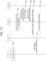
- FIG. 11 shows an example of a procedure for informing a CU-UP of an MT-SDT support indication to which the first implementation of the present disclosure is applied.
- FIG. 11 shows, in the process of the UE transitioning to the RRC_INACTIVE state, a method in which the CU-CP informs the CU-UP that the corresponding UE supports MT-SDT, and accordingly, when DL data is received through the bearer associated with the SDT afterwards, requests to inform the CU-CP of the size of the DL data.
- the procedure of FIG. 11 may be performed before the method described with reference to FIGS. 9 and/or 10 described above. Also, the procedure of FIG. 11 may be performed before the procedure of FIGS. 12 and 13 to be described later.
- the CU-CP may inform the CU-UP of the MT-SDT Support Indication together. Based on this, the CU-UP may know that the corresponding UE supports MT-SDT in the RRC_lNACTlVE state, and therefore, when DL data is received from the UPF, that the size of the corresponding DL data should be informed to the CU-CP.
- the CU-CP may inform the CU-UP of only the list of bearers to be used for MT-SDT instead of the MT-SDT Support Indication, and/or inform both of them. Therefore, when the CU-UP receives DL data from the UPF for the corresponding bearer, the CU-UP may inform the CU-CP of the size of the DL data as well.
- the DU may keep the related information (e.g., CG-SDT related bearer ID, UL TNL address, CG-SDT configuration information, etc.) without releasing it.
- the DU may know this through a separate indicator notifying the CG-SDT, which is included in the UE CONTEXT RELEASE COMMAND message.
- the DU may keep the related information (e.g., information about bearer related to RA-SDT, information about bearer related to CG-SDT, etc.) without releasing it.
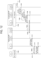
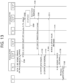
- FIGS. 12 and 13 show an example of a procedure for supporting MT-SDT in CU-DU split considering SDT without anchor relocation to which the first implementation of the present disclosure is applied.
- FIGS. 12 and 13 shows, when DL data for a bearer related to MT-SDT arrives at the CU-UP of the last serving NG-RAN, a method in which the CU-UP of the last serving NG-RAN informs the CU-CP of the last serving NG-RAN of the size of DL data, so that the CU-CP of the last serving NG-RAN can determine whether to initiate MT-SDT for the UE.
- FIGS. 12 and 13 shows, when DL data for a bearer related to MT-SDT arrives at the CU-UP of the last serving NG-RAN, a method in which the CU-UP of the last serving NG-RAN informs the CU-CP of the last serving NG-RAN of the size of DL data, so that the CU-CP of the last serving NG-RAN can determine whether to initiate MT-SDT for the UE.
- 12 and 13 shows, by notifying the DU of the new NG-RAN (or the receiving NG-RAN) that MT-SDT is currently in progress, a method in which the DU of the receiving NG-RAN pre-allocates a DL TNL address from which the DU of the receiving NG-RAN can receive DL data forwarded from the CU-UP of the last serving NG-RAN when the UE starts the RRC resume procedure.
- FIGS. 12 and 13 it is assumed that the receiving NG-RAN and the last serving NG-RAN are separated into a CU-CP, a CU-UP, and a DU.
- this is only an example, and the first implementation of the present disclosure is applicable even when any one of the receiving NG-RAN and the last serving NG-RAN are not separated into CU-CP, CU-UP, and DU.
- FIGS. 12 and 13 may correspond to some steps in FIGS. 9 and/or 10 described above.
- the procedure of FIGS. 12 and 13 may be performed following the procedure of FIG. 11 described above.
- the UE receives SDT-related configurations (e.g., bearer ID to be used for SDT, SDT data volume threshold, etc.) from the last serving NG-RAN in the process of transitioning to the RRC_lNACTlVE state.
- SDT-related configurations e.g., bearer ID to be used for SDT, SDT data volume threshold, etc.
- Both CU-CP and CU-UP of the last serving NG-RAN maintain the corresponding information. If CG-SDT is configured for the UE, the UE, the CU-CP, the CU-UP, and the DU of the last serving NG-RAN all also have information related thereto.
- the SDT threshold for determining whether to transmit DL data for the UE using the MT-SDT may be previously generated and stored by the CU-CP of the last serving NG-RAN when the corresponding UE is in the RRC _CONNECTED state.
- the DU of the last serving NG-RAN may transmit a related value to the CU of the last serving NG-RAN in advance.
- the DU of the last serving NG-RAN may generate an SDT threshold and deliver it to the CU-CP of the last serving NG-RAN, and the CU-CP of the last serving NG-RAN may continuously store it.
- the CU-CP of the last serving NG-RAN may request the DU of the last serving NG-RAN to generate an SDT threshold.
- the MT-SDT Indication may include bearer ID information to be used for MT-SDT.
- the CU-CP of the last serving NG-RAN may first attempt a paging procedure for a cell in the DU of the last serving NG-RAN to which the CG-SDT resource is allocated. In this way, it is possible to prevent unnecessary waste of paging-related resources.
- the DU of the last serving NG-RAN may notify the CU-CP of the last serving NG-RAN when the timer related to the CG SDT resource expires.
- the CU-CP of the last serving NG-RAN may wait for a response from the UE by attempting a paging procedure in a wider range.
- Step S1208 and step S1210 may be performed simultaneously.
- the UE may perform the RACH procedure of step S1214 in response to step S1209. In this case, the subsequent operations takes place for the last serving NG-RAN rather than the receiving NG-RAN, and steps S1302 and S1308 of FIG. 13 to be described later are omitted.
- the DU of the receiving NG-RAN responds to the CU-CP of the receiving NG-RAN with a UE CONTEXT RELEASE COMPLETE message.
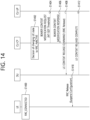
- FIG. 14 shows an example of a procedure for informing a CU-UP of an MT-SDT support indication to which the second implementation of the present disclosure is applied.
- FIG. 14 shows, in the process of the UE transitioning to the RRC _INACTIVEstate, a method in which the CU-CP transmits the SDT threshold to the CU-UP in advance to inform that the UE supports MT-SDT, and accordingly, when DL data is received through the bearer associated with the SDT afterwards, requests to inform the CU-CP by comparing the size of DL data and the SDT threshold.
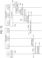
- the procedure of FIG. 14 may be performed before the method described with reference to FIGS. 9 and/or 10 described above. Also, the procedure of FIG. 14 may be performed before the procedure of FIGS. 15 and 16 to be described later.
- the CU-CP may inform the CU-UP of the SDT threshold together. Based on this, the CU-UP may know that the corresponding UE supports MT-SDT in the RRC_INACTIVE state, and when DL data is received from the UPF, as shown in FIG. 15 which will be described later, that the CU-UP should compare the size of the corresponding DL data and the SDT threshold for the corresponding UE and inform the result to the CU-CP.
- the SDT threshold for determining whether to transmit DL data for the UE using the MT-SDT may be previously generated and stored by the CU-CP of the last serving NG-RAN when the corresponding UE is in the RRC _CONNECTED state.
- the DU of the last serving NG-RAN may transmit a related value to the CU of the last serving NG-RAN in advance.
- the DU of the last serving NG-RAN may generate an SDT threshold and deliver it to the CU-CP of the last serving NG-RAN, and the CU-CP of the last serving NG-RAN may continuously store it.
- the CU-CP of the last serving NG-RAN may request the DU of the last serving NG-RAN to generate an SDT threshold.
- the CU-CP may inform the CU-UP of the list of bearers to be used for MT-SDT. Therefore, when the CU-UP receives DL data from the UPF for the corresponding bearer, the CU-UP may inform the CU-CP of the size of the DL data as well.
- the DU may keep the related information (e.g., CG-SDT related bearer ID, UL TNL address, CG-SDT configuration information, etc.) without releasing it.
- the DU may know this through a separate indicator notifying the CG-SDT, which is included in the UE CONTEXT RELEASE COMMAND message.
- the DU may keep the related information (e.g., information about bearer related to RA-SDT, information about bearer related to CG-SDT, etc.) without releasing it.
- FIGS. 15 and 16 show an example of a procedure for supporting MT-SDT in CU-DU split considering SDT without anchor relocation to which the second implementation of the present disclosure is applied.
- FIGS. 15 and 16 shows, when DL data for a bearer related to MT-SDT arrives at the CU-UP of the last serving NG-RAN, a method in which the CU-UP of the last serving NG-RAN compares the size of DL data with the SDT threshold and informs the CU-CP of the last serving NG-RAN of the result, so that the CU-CP of the last serving NG-RAN can determine whether to initiate MT-SDT for the UE.
- FIGS. 15 and 16 shows, when DL data for a bearer related to MT-SDT arrives at the CU-UP of the last serving NG-RAN, a method in which the CU-UP of the last serving NG-RAN compares the size of DL data with the SDT threshold and informs the CU-CP of the last serving NG-RAN of the result, so that the CU-CP of the last serving NG-RAN can determine whether to initiate MT-SDT for the UE.
- FIGS. 15 and 16 shows,
- 15 and 16 shows, by notifying the DU of the new NG-RAN (or the receiving NG-RAN) that MT-SDT is currently in progress, a method in which the DU of the receiving NG-RAN pre-allocates a DL TNL address from which the DU of the receiving NG-RAN can receive DL data forwarded from the CU-UP of the last serving NG-RAN when the UE starts the RRC resume procedure.
- FIGS. 15 and 16 it is assumed that the receiving NG-RAN and the last serving NG-RAN are separated into a CU-CP, a CU-UP, and a DU.
- this is only an example, and the second implementation of the present disclosure is applicable even when any one of the receiving NG-RAN and the last serving NG-RAN are not separated into CU-CP, CU-UP, and DU.
- FIGS. 15 and 16 may correspond to some steps in FIGS. 9 and/or 10 described above.
- the procedure of FIGS. 15 and 16 may be performed following the procedure of FIG. 14 described above.
- the UE receives SDT-related configurations (e.g., bearer ID to be used for SDT, SDT data volume threshold, etc.) from the last serving NG-RAN in the process of transitioning to the RRC_lNACTlVE state.
- SDT-related configurations e.g., bearer ID to be used for SDT, SDT data volume threshold, etc.
- Both CU-CP and CU-UP of the last serving NG-RAN maintain the corresponding information. If CG-SDT is configured for the UE, the UE, the CU-CP, the CU-UP, and the DU of the last serving NG-RAN all also have information related thereto.
- the CU-UP of the last serving NG-RAN may inform the CU-CP of the last serving NG-RAN of the comparison result of the size of the received DL data and the SDT threshold derived in step S1504 together.
- the CU-UP of the last serving NG-RAN may transmit an MT-SDT Required Indication to inform the CU-CP of the last serving NG-RAN that MT-SDT is required for the corresponding UE.
- the bearer ID to which the DL data has arrived may be transmitted together with the MT-SDT Required Indication.
- the MT-SDT Indication may include bearer ID information to be used for MT-SDT.
- the CU-CP of the last serving NG-RAN may first attempt a paging procedure for a cell in the DU of the last serving NG-RAN to which the CG-SDT resource is allocated. In this way, it is possible to prevent unnecessary waste of paging-related resources.
- the DU of the last serving NG-RAN may notify the CU-CP of the last serving NG-RAN when the timer related to the CG SDT resource expires.
- the CU-CP of the last serving NG-RAN may wait for a response from the UE by attempting a paging procedure in a wider range.
- Step S1510 and step S1512 may be performed simultaneously.
- the UE may perform the RACH procedure of step S1516 in response to step S1511. In this case, the subsequent operations takes place for the last serving NG-RAN rather than the receiving NG-RAN, and steps S1602 and S1608 of FIG. 16 to be described later are omitted.
- the DU of the receiving NG-RAN responds to the CU-CP of the receiving NG-RAN with a UE CONTEXT RELEASE COMPLETE message.
- the present disclosure may have various advantageous effects.
- the CU-CP can determine whether to attempt MT-SDT while maintaining the RRC _INACTIVE state for the UE or to transition the UE to the RRC_CONNECTED state.
- MT-SDT when MT-SDT is applicable, it is possible to prevent the UE from receiving DL data after unnecessarily transitioning to the RRC _CONNECTED state.
- the new gNB can quickly create a DL data forwarding tunnel, so that the DL data is quickly delivered through the MT-SDT.
Landscapes
- Engineering & Computer Science (AREA)
- Computer Networks & Wireless Communication (AREA)
- Signal Processing (AREA)
- Databases & Information Systems (AREA)
- Mobile Radio Communication Systems (AREA)
Applications Claiming Priority (1)
| Application Number | Priority Date | Filing Date | Title |
|---|---|---|---|
| KR20220000378 | 2022-01-03 |
Publications (1)
| Publication Number | Publication Date |
|---|---|
| EP4207844A1 true EP4207844A1 (fr) | 2023-07-05 |
Family
ID=83689880
Family Applications (1)
| Application Number | Title | Priority Date | Filing Date |
|---|---|---|---|
| EP22200650.4A Pending EP4207844A1 (fr) | 2022-01-03 | 2022-10-10 | Prise en charge de mt-sdt en considération de la division cu-du |
Country Status (3)
| Country | Link |
|---|---|
| US (2) | US20230217532A1 (fr) |
| EP (1) | EP4207844A1 (fr) |
| KR (1) | KR20230105304A (fr) |
Cited By (1)
| Publication number | Priority date | Publication date | Assignee | Title |
|---|---|---|---|---|
| WO2024082725A1 (fr) * | 2023-07-13 | 2024-04-25 | Lenovo (Beijing) Limited | Dispositifs et procédés de communication |
Families Citing this family (7)
| Publication number | Priority date | Publication date | Assignee | Title |
|---|---|---|---|---|
| EP4409996A4 (fr) * | 2022-04-24 | 2024-12-04 | ZTE Corporation | Procédés, dispositifs et systèmes pour la transmission de petites données |
| US12495392B2 (en) * | 2022-11-03 | 2025-12-09 | T-Mobile Usa, Inc. | Paging message for mobile terminating small data transmission |
| CN119343987A (zh) * | 2022-11-18 | 2025-01-21 | 上海诺基亚贝尔股份有限公司 | 用于数据传输的设备、方法和装置 |
| US20240188038A1 (en) * | 2023-02-16 | 2024-06-06 | Intel Corporation | Support for mobile terminated small data transmission in fifth generation systems |
| CN119497262A (zh) * | 2023-08-18 | 2025-02-21 | 中电信智能网络科技有限公司 | 数据传输的方法及装置 |
| CN117729652B (zh) * | 2024-02-07 | 2024-07-02 | 荣耀终端有限公司 | 通信方法、设备和存储介质 |
| US12376158B1 (en) * | 2024-03-29 | 2025-07-29 | Metapex Inc. | Method and apparatus for small data transmission |
Citations (3)
| Publication number | Priority date | Publication date | Assignee | Title |
|---|---|---|---|---|
| US20200053791A1 (en) * | 2018-08-13 | 2020-02-13 | Qualcomm Incorporated | Downlink data transmission in rrc inactive mode |
| WO2020191059A1 (fr) * | 2019-03-19 | 2020-09-24 | Apple Inc. | Signalisation de transmission de petites données inactive sans commutation de chemin |
| WO2021150015A1 (fr) * | 2020-01-22 | 2021-07-29 | Lg Electronics Inc. | Procédé et appareil pour transmission rapide de petites données dans un système de communication sans fil |
-
2022
- 2022-09-20 KR KR1020220118368A patent/KR20230105304A/ko active Pending
- 2022-10-04 US US17/959,678 patent/US20230217532A1/en not_active Abandoned
- 2022-10-10 EP EP22200650.4A patent/EP4207844A1/fr active Pending
-
2025
- 2025-09-03 US US19/317,743 patent/US20260006677A1/en active Pending
Patent Citations (3)
| Publication number | Priority date | Publication date | Assignee | Title |
|---|---|---|---|---|
| US20200053791A1 (en) * | 2018-08-13 | 2020-02-13 | Qualcomm Incorporated | Downlink data transmission in rrc inactive mode |
| WO2020191059A1 (fr) * | 2019-03-19 | 2020-09-24 | Apple Inc. | Signalisation de transmission de petites données inactive sans commutation de chemin |
| WO2021150015A1 (fr) * | 2020-01-22 | 2021-07-29 | Lg Electronics Inc. | Procédé et appareil pour transmission rapide de petites données dans un système de communication sans fil |
Non-Patent Citations (1)
| Title |
|---|
| "3rd Generation Partnership Project; Technical Specification Group Radio Access Network; NR; NR and NG-RAN Overall Description; Stage 2 (Release 16)", vol. RAN WG2, no. V16.8.0, 23 December 2021 (2021-12-23), pages 1 - 152, XP052083416, Retrieved from the Internet <URL:https://ftp.3gpp.org/Specs/archive/38_series/38.300/38300-g80.zip 38300-g80.docx> [retrieved on 20211223] * |
Cited By (2)
| Publication number | Priority date | Publication date | Assignee | Title |
|---|---|---|---|---|
| WO2024082725A1 (fr) * | 2023-07-13 | 2024-04-25 | Lenovo (Beijing) Limited | Dispositifs et procédés de communication |
| GB2642014A (en) * | 2023-07-13 | 2025-12-24 | Lenovo Beijing Ltd | Devices and methods of communication |
Also Published As
| Publication number | Publication date |
|---|---|
| KR20230105304A (ko) | 2023-07-11 |
| US20230217532A1 (en) | 2023-07-06 |
| US20260006677A1 (en) | 2026-01-01 |
Similar Documents
| Publication | Publication Date | Title |
|---|---|---|
| EP4207844A1 (fr) | Prise en charge de mt-sdt en considération de la division cu-du | |
| US12581569B2 (en) | Method for supporting service continuity when disaster situation ends, and device supporting same | |
| US11924287B2 (en) | Method for managing session | |
| US12470987B2 (en) | N14 interface support indicator for service continuity | |
| US12335854B2 (en) | Communication related to network slice | |
| US12563454B2 (en) | Communication related to UE context | |
| EP4329417A1 (fr) | Procédé de gestion de session pdu redondante pour transmission redondante | |
| US20230217454A1 (en) | Sidelink resource allocation and mac reset | |
| KR20230029811A (ko) | Snpn과 분리되어 있는 개체가 소유하는 자격 증명을 이용한 snpn 접속 및 이를 위한 f1 인터페이스 지원 | |
| EP4224930B1 (fr) | Support de continuité de service pour une session pdu à routage domestique lorsqu'il n'y a pas d'interface n14 entre un réseau source et un réseau cible | |
| EP4109975A1 (fr) | Communication relative à une tranche de réseau | |
| US12232191B2 (en) | Session management method | |
| EP4199586A1 (fr) | Procédé de gestion de session | |
| US12425951B2 (en) | Method for managing prohibited PLMN list during disaster roaming, and apparatus supporting same | |
| US12538111B2 (en) | Method for notifying of disaster situation by RAN node, and device supporting same | |
| EP4475601A1 (fr) | Procédé de gestion de mbsr | |
| US12432626B2 (en) | Communication method via network slice | |
| US20260059583A1 (en) | Terminal power management method | |
| US12538246B2 (en) | Method for synchronization between UEs according to change in reference synchronization source in V2X communication system, and device therefor | |
| EP4598074A1 (fr) | Procédé de détermination de règle d´ursp | |
| KR20250170058A (ko) | 레이턴시 측정 방법 | |
| KR20220087553A (ko) | 통신 방법 및 장치 |
Legal Events
| Date | Code | Title | Description |
|---|---|---|---|
| PUAI | Public reference made under article 153(3) epc to a published international application that has entered the european phase |
Free format text: ORIGINAL CODE: 0009012 |
|
| STAA | Information on the status of an ep patent application or granted ep patent |
Free format text: STATUS: REQUEST FOR EXAMINATION WAS MADE |
|
| 17P | Request for examination filed |
Effective date: 20221010 |
|
| AK | Designated contracting states |
Kind code of ref document: A1 Designated state(s): AL AT BE BG CH CY CZ DE DK EE ES FI FR GB GR HR HU IE IS IT LI LT LU LV MC ME MK MT NL NO PL PT RO RS SE SI SK SM TR |
|
| STAA | Information on the status of an ep patent application or granted ep patent |
Free format text: STATUS: EXAMINATION IS IN PROGRESS |
|
| 17Q | First examination report despatched |
Effective date: 20260126 |