EP4207941A1 - Transparente heizung und entwurfsverfahren dafür - Google Patents
Transparente heizung und entwurfsverfahren dafür Download PDFInfo
- Publication number
- EP4207941A1 EP4207941A1 EP21861752.0A EP21861752A EP4207941A1 EP 4207941 A1 EP4207941 A1 EP 4207941A1 EP 21861752 A EP21861752 A EP 21861752A EP 4207941 A1 EP4207941 A1 EP 4207941A1
- Authority
- EP
- European Patent Office
- Prior art keywords
- heater
- transparent
- designing
- information
- pattern
- Prior art date
- Legal status (The legal status is an assumption and is not a legal conclusion. Google has not performed a legal analysis and makes no representation as to the accuracy of the status listed.)
- Pending
Links
Images




Classifications
-
- H—ELECTRICITY
- H05—ELECTRIC TECHNIQUES NOT OTHERWISE PROVIDED FOR
- H05K—PRINTED CIRCUITS; CASINGS OR CONSTRUCTIONAL DETAILS OF ELECTRIC APPARATUS; MANUFACTURE OF ASSEMBLAGES OF ELECTRICAL COMPONENTS
- H05K3/00—Apparatus or processes for manufacturing printed circuits
- H05K3/10—Apparatus or processes for manufacturing printed circuits in which conductive material is applied to the insulating support in such a manner as to form the desired conductive pattern
-
- H—ELECTRICITY
- H05—ELECTRIC TECHNIQUES NOT OTHERWISE PROVIDED FOR
- H05B—ELECTRIC HEATING; ELECTRIC LIGHT SOURCES NOT OTHERWISE PROVIDED FOR; CIRCUIT ARRANGEMENTS FOR ELECTRIC LIGHT SOURCES, IN GENERAL
- H05B3/00—Ohmic-resistance heating
- H05B3/84—Heating arrangements specially adapted for transparent or reflecting areas, e.g. for demisting or de-icing windows, mirrors or vehicle windshields
-
- H—ELECTRICITY
- H05—ELECTRIC TECHNIQUES NOT OTHERWISE PROVIDED FOR
- H05B—ELECTRIC HEATING; ELECTRIC LIGHT SOURCES NOT OTHERWISE PROVIDED FOR; CIRCUIT ARRANGEMENTS FOR ELECTRIC LIGHT SOURCES, IN GENERAL
- H05B2203/00—Aspects relating to Ohmic resistive heating covered by group H05B3/00
- H05B2203/013—Heaters using resistive films or coatings
-
- H—ELECTRICITY
- H05—ELECTRIC TECHNIQUES NOT OTHERWISE PROVIDED FOR
- H05B—ELECTRIC HEATING; ELECTRIC LIGHT SOURCES NOT OTHERWISE PROVIDED FOR; CIRCUIT ARRANGEMENTS FOR ELECTRIC LIGHT SOURCES, IN GENERAL
- H05B2203/00—Aspects relating to Ohmic resistive heating covered by group H05B3/00
- H05B2203/017—Manufacturing methods or apparatus for heaters
Definitions
- the present invention relates to a transparent heater and a designing method for the same.
- Patent Literature 1 discloses, as such heater usage, a transparent conductive film comprising a mesh pattern constituted by a plurality of conductive thin metal lines, and discloses that the thin metal lines are provided in a wavy line shape.
- Patent Literature 2 discloses a transparent heater in which a plurality of heat lines are disposed in a mesh shape, and discloses that current density is controlled at intersections of the heat lines.
- the present invention has been made in view of the above-described problem and intended to provide a designing method by which a transparent heater that can achieve desired transparent and heat generation properties can be more easily designed, and a transparent heater designed by the method.
- the present invention is as follows.
- the present invention it is possible to provide a designing method by which a transparent heater that can achieve desired transparent and heat generation properties can be more easily designed, and a transparent heater designed by the method.
- the present embodiment An embodiment of the present invention (hereinafter referred to as “the present embodiment”) will be described below in detail but does not limit the present invention and may be modified in various manners without departing from the scope.
- a transparent-heater designing method of the present embodiment is a designing method by an information processing device for a transparent heater comprising a transparent base material and a heater unit, the heater unit comprising a conductive pattern formed on a surface of or inside the transparent base material.
- FIG. 1 illustrates a top view of a transparent heater comprising a conductive pattern in a mesh shape as an aspect of a transparent heater of the present embodiment
- Figure 2 illustrates a perspective view of a region S in Figure 1
- a transparent heater 100 of the present embodiment comprises a heater unit 120 comprising a conductive pattern 130 on the surface of or inside a transparent base material 110.
- the conductive pattern 130 comprised in the heater unit 120 is, for example, a pattern comprising conductive thin lines 140.
- the conductive pattern 130 is electrically connected to a power source 150 through electrodes (not illustrated), and the conductive pattern 130 generates heat and the transparent heater 100 exerts a heater function as current flows from the power source 150 to the conductive pattern.
- the conductive pattern 130 may be a grid pattern (mesh pattern) in which the conductive thin lines 140 intersect as illustrated in Figure 1 or may be a line pattern, and it is possible to control a transparent property, a heat generation capacity, or thermal responsiveness to be described later in accordance with the thickness and density of the conductive thin lines 140 thus configured.
- the transparent-heater designing method of the present embodiment estimates designing information that serves as a guide for the configuration of the conductive pattern 130 to obtain a desired transparent property and a desired heat generation capacity.
- a system is established that estimates, by an information processing device 300 that is a designing device, designing information DI based on a transmissivity T and a heat generation capacity C as targets of the transparent heater 100, the designing information DI comprising information related to the thickness of a conductive thin line comprised in the conductive pattern 130 and information related to a pattern shape PAT of the conductive pattern 130.
- Figure 3 is a diagram illustrating an example of a hardware configuration and a functional configuration of the information processing device 300 according to the present embodiment.
- the information processing device 300 typically comprises one or a plurality of processors 310, a communication interface 320 configured to control wired or wireless communication, an input-output interface 330, a memory 340, a storage 350, and one or a plurality of communication buses 360 for mutually connecting these constituent components, and processing, a function, or a method described in the present disclosure is achieved by cooperation of the components.
- Such a terminal is, for example, a personal computer, a touch panel, or a tablet.
- Each processor 310 executes processing, a function, or a method achieved by a code or a command comprised in a program stored in the memory 340.
- the processor 310 comprises, not as a limitation but as an example, one or a plurality of central processing units (CPU) and graphics processing units (GPU).
- the communication interface 320 transmits and receives various kinds of data to and from another information processing device through a network. This communication may be executed in any of wired and wireless manners, and any communication protocol may be used as long as communication can be executed between each other.
- the communication interface 320 is implemented as a hardware component such as a network adapter, various communication software components, or a combination thereof.
- the input-output interface 330 comprises an input device that inputs various operations on the information processing device 300, and an output device that outputs a result of processing by the information processing device 300.
- the input-output interface 330 comprises an information input device such as a keyboard, a mouse, or a touch panel, and an information output device such as a display device.
- the memory 340 temporarily stores a program loaded from the storage 350 and provides a work area to the processor 310.
- the memory 340 also temporarily stores various kinds of data generated while a program is executed by the processor 310.
- the memory 340 may be, not as a limitation but as an example, a high-speed random-access memory such as a ROM, a DRAM, an SRAM, a DDR RAM, or any other random-access solid storage device or may be a combination thereof.
- the storage 350 stores programs, various kinds of functional units, and various kinds of data.
- the storage 350 may be, not as a limitation but as an example, a non-transitory memory such as a magnetic disk storage device, an optical disk storage device, a flash memory device, or any other non-transitory solid storage device or may be a combination thereof.
- Other examples of the storage 350 comprise one or a plurality of storage devices installed remotely from the processor 310.
- the storage 350 stores programs, functional components, and data structures, or a subset thereof.
- the information processing device 300 functions as a designing processing unit 343 and a display control unit 344 as commands comprised in a program stored in the storage 350 are executed by the processor 310.
- An operating system 341 processes, for example, various basic system services and comprises a procedure for executing a task by using hardware.
- a network communication unit 342 is used to connect the information processing device 300 to another device such as a mask manufacturing device, a plate manufacturing device, or a conductive pattern formation device through the communication interface 320 and a network and functions as a transmission-reception unit for various kinds of information.
- the designing processing unit 343 executes processing of estimating, based on the transmissivity T and the heat generation capacity C as targets of the transparent heater 100, the designing information DI comprising information related to the thickness of each conductive thin line 140 comprised in the conductive pattern 130 and information related to the pattern shape PAT of the conductive pattern 130.
- the designing processing unit 343 may receive information related to the transmissivity T and the heat generation capacity C as targets from a designer through the input-output interface 330.
- the designing processing unit 343 may execute processing of estimating the designing information DI further comprising information related to a power source capacity E 0 connected to the transparent heater. Accordingly, the power source capacity E 0 suitable for the designed transparent heater 100 can be designated, and thus it is possible to achieve the transparent heater that can effectively exploit the power source capacity, and also it is possible to prevent connection of a power source the power source capacity E 0 of which is excessively large.
- the information related to the power source capacity E 0 may additionally comprise information related to thermal responsiveness when the power source capacity E 0 is selected. As described later, there is a tendency that the heat generation capacity C is restricted by the power source capacity E 0 and the heat releasing capacity is not restricted by the power source capacity E 0 . Thus, the thermal responsiveness of the transparent heater, for example, the ratio of the heat generation capacity C and a heat releasing capacity D (the heat generation capacity C/the heat releasing capacity D) changes in accordance with the power source capacity E 0 .
- the designing information DI comprises information related to such thermal responsiveness as the information related to the power source capacity E 0 , the designer can immediately understand the degree of thermal responsiveness obtained when the transparent heater is connected to the power source capacity E 0 .
- the designing processing unit 343 may execute processing of estimating the designing information DI further based on thermal responsiveness as a target of the transparent heater 100.
- the designing processing unit 343 may receive information related to the target thermal responsiveness from the designer through the input-output interface 330.
- predetermined thermal responsiveness is required for a heater in accordance with the usage and purpose thereof. For example, when a heater is bonded to the surface of a camera lens and used, it is assumed that precise temperature control is required for the heater and such heat response performance that the heater is easily heated and cooled is required to finely control the temperature of the heater. In usage for preventing fog or frost generation on a window glass or a vehicle front glass, it is assumed that such heat response performance that the heater is less likely to be cooled is required for the heater to maintain generated heat after electric power supply is stopped.
- the designing processing unit 343 may transmit the designing information DI to another device through the transmission-reception unit.
- the other device is, for example, a device that manufactures the transparent heater 100 by using the designing information DI, or a device that manufactures a member used to manufacture the transparent heater 100. More specifically, examples of the member used to manufacture the transparent heater 100 comprise a mask and a plate, and examples of the device that manufactures these members comprise a mask manufacturing device and a plate manufacturing device.
- the device that manufactures the transparent heater 100 by using the designing information DI is not particularly limited but is, for example, a device that manufactures the transparent heater 100 by photolithography or the like using a mask, a device that manufactures the transparent heater 100 by a plate printing method using a plate, or a device that manufactures the transparent heater 100 by an ink-jet method or the like. Note that devices that manufacture the transparent heater 100 by using the designing information DI are collectively referred to as "conductive pattern formation devices" in some cases.
- the designing processing unit 343 may transmit the designing information DI to both the mask manufacturing device and the device that manufactures the transparent heater 100 by a photolithography method or the like using a mask, or both the plate manufacturing device and the device that manufactures the transparent heater 100 by the plate printing method using a plate.
- information related to a planar view shape such as a line width W 1 and the pattern shape PAT of the conductive pattern 130 among pieces of information comprised in the designing information DI can be used by the mask manufacturing device and the plate manufacturing device
- information related to a stereoscopic shape such as the cross-sectional area of the conductive pattern 130 and the film thickness of each conductive thin line 140 among pieces of information comprised in the designing information DI can be used by the device that manufactures the transparent heater 100.
- the display control unit 344 may control display of the designing information DI estimated by the designing processing unit 343 on a display device.
- the display control of the designing information DI is not limited to a particular aspect, but for example, information related to the thickness of each conductive thin line 140 and information related to the pattern shape PAT of the conductive pattern 130 may be displayed by text or may be displayed as two-dimensional or three-dimensional graphs as illustrated in Figures 6 and 7 .
- the display control unit 344 may control display of adjacent designing information DI' in addition to the designing information DI on the display device, the adjacent designing information DI' being estimated based on a transmissivity T' and a heat generation capacity C' adjacent to the transmissivity T and the heat generation capacity C as targets. For example, when the target transmissivity T is 88 to 90%, the range of "being adjacent" is a range higher or lower than the target transmissivity T, such as 86 to 88% or 90 to 92%. With the display control of the adjacent designing information DI' estimated based on the transmissivity T' and the heat generation capacity C', the designing information when the transmissivity is increased or decreased can be understood as reference information and designing can be easily performed.
- the display control of the adjacent designing information DI' is not limited to a particular aspect, but for example, similarly to the designing information DI, the adjacent designing information DI' may be displayed by text or may be displayed as two-dimensional or three-dimensional graphs as illustrated in Figures 6 and 7 .
- the display control unit 344 may highlight the designing information DI in the display control.
- the following describes operation of the information processing device 300 according to the embodiment of the present invention thus configured.
- designing processing will be described before specific aspects of a designing step in which the designing processing unit 343 estimates the designing information DI is described. Note that the designing step is not limited to a particular aspect but has, for example, patterns 1 to 7 below.
- the "transmissivity T" in the present embodiment means the visible light transmissivity at a part where the conductive pattern 130 is formed in the transparent heater 100. Note that a value estimated based on the conductive pattern may be used as the transmissivity T in place of the actual value of the visible light transmissivity.
- the line width W 1 of each conductive thin line 140 is preferably designed to be 10 ⁇ m or smaller.
- the line width W 1 of each conductive thin line 140 is sufficiently small at, for example, 10 ⁇ m or smaller, visibility of the conductive thin line 140 decreases and the transparent property of the transparent heater further improves.
- an opening ratio RO can be estimated by Expression (1) below as the ratio of the area of a part where no conductive thin line 140 is provided in the heater unit 120 having a predetermined area.
- Expression (1) below can be expressed by line widths W 11 and W 12 , opening widths W 21 and W 22 , pitches P 1 and P 2 as described below.
- the transmissivity T can be approximated by Expression (2) below by using the above-described opening ratio RO, the transmissivity of the transparent base material 110, and the transmissivity of each conductive thin line 140.
- Expression (2) below can be estimated by setting the transmissivity of each conductive thin line 140 to zero when it can be regarded that the conductive thin line 140 does not transmit light.
- the transmissivity T % the transmissivity of the transparent base material ⁇ the opening ratio RO % + the transmissivity of the transparent base material ⁇ the transmissivity of the conductive thin line ⁇ 100 ⁇ the opening ratio RO % / 100
- the transmissivity of the transparent base material and the transmissivity of the conductive thin line described above are may be those stored in advance, in accordance with a used material or the like, or may be those input from the designer through the input-output interface 330.
- line widths in a case of a rectangular grid pattern as in Figures 1 and 2 are referred to as the line widths W 11 and W 12 in accordance with directions, and are simply referred to as the line width W 1 when not distinguished based on directions.
- opening widths in a case of a rectangular grid pattern are referred to as the opening width W 21 , W 22 , and are simply referred to as an opening width W 2 when not distinguished based on directions. This is the same for a pitch P.
- the "heat generation capacity C" means the heat generation capacity at the conductive pattern 130 of the transparent heater 100 and can be expressed by electric power E consumed by the conductive pattern 130.
- a sheet resistivity Rs can be estimated based on the specific resistance of the conductive thin line and cross-sectional area Sm of the conductive thin line 140 per unit length of the heater unit 120.
- the sheet resistivity Rs can be expressed by Expression (3) below, which is proportional to the specific resistance of the conductive thin line and inversely proportional to the cross-sectional area Sm.
- the sheet resistivity Rs decreases when it is designed that the cross-sectional area Sm increases.
- the sheet resistivity Rs a coefficient k 1 ⁇ the specific resistance of the conductive thin line / the cross ⁇ sectional area Sm of the conductive thin line per unit length of the heater unit
- the coefficient k 1 coefficient as a collection of terms other than the specific resistance and Sm
- the above-described specific resistance of the conductive thin line may be that stored in advance, in accordance with a used material or the like, or may be that input from the designer through the input-output interface 330.
- the sheet resistivity Rs can be obtained by estimating the cross-sectional area Sm based on a combination of the thickness of the conductive thin line and the pattern shape.
- the sheet resistivity Rs can be expressed by Expression (4) below by using the film thickness H and the opening ratio RO by approximating Sm to W 1 ⁇ H/P by using the line width W 1 , a film thickness H, and the pitch P and rearranging W 1 /P as a function of the opening ratio RO by using Expression (1) of the opening ratio RO.
- Figure 4 illustrates an exemplary trial graph of estimation of the sheet resistivity based on the opening ratio and the film thickness.
- the sheet resistivity Rs a coefficient k 2 ⁇ the specific resistance of the conductive thin line / the film thickness H of the conductive thin line ⁇ 1 + the opening ratio RO % / 100 1 / 2 / 1 ⁇ the opening ratio RO % / 100
- the coefficient k 2 coefficient as a collection of terms other than those explicitly written in Expression (4)
- the resistance value of the heater for estimating electric power consumption E of the heater can be estimated by Expression (5) below by using the sheet resistivity Rs.
- the electric power E consumed at any resistor of the conductive pattern 130 comprised in the heater unit 120 of the predetermined length L1 and the predetermined width L2 is proportional to power voltage V 0 and inversely proportional to the sheet resistivity Rs and thus is expressed by Expression (6) below.
- the resistance value R of the heater Rs ⁇ L1/L2
- the electric power E consumed at the resistor V 0 2 / R
- the electric power consumption E can be expressed as a function of the cross-sectional area Sm as in Expression (7).
- the cross-sectional area Sm can be estimated based on the line width W 1 , the film thickness H, and the pitch P, and thus the electric power consumption E can be expressed as a function of the line width W 1 , the film thickness H, and the pitch P.
- the electric power E consumed at the resistor increases when it is designed that the sheet resistivity Rs decreases.
- the electric power E consumed at the resistor a coefficient k 3 ⁇ V 0 2 ⁇ the cross ⁇ sectional area Sm
- the coefficient k 3 coefficient as a collection of terms other than V 0 and Sm
- the "heat releasing capacity D" means the heat releasing capacity at the conductive pattern 130 of the transparent heater 100 and can be expressed by the likelihood of heat decrease of the conductive pattern 130. For example, when it is assumed that heat is released mainly through heat transfer from the conductive pattern 130 to the electrodes, the heat releasing capacity D increases in proportion to the cross-sectional area (W 1 ⁇ H) of the conductive thin line 140 and decreases in proportion to the pitch. For example, the heat releasing capacity D can be expressed by Expression (8) below.
- the heat releasing capacity D a coefficient k 4 ⁇ the cross ⁇ sectional area W 1 ⁇ H of the conductive thin line / the pitch P of the conductive thin line
- the coefficient k 4 coefficient as a collection of terms other than those explicitly written in Expression (8)
- the combination of W 11 and P 1 or the combination of W 12 and P 2 may be used as the combination of W 1 and P in accordance with electrode disposition of the transparent heater.
- the "designing information DI" comprises the information related to the thickness of each conductive thin line comprised in the conductive pattern, and the pattern shape PAT of the conductive pattern. Accordingly, the conductive pattern 130 can be formed in the predetermined pattern shape PAT with the conductive thin lines 140 of the predetermined thickness.
- Examples of the information related to the thickness of each conductive thin line 140 comprise the line width W 1 , a cross-sectional area S, the film thickness H, and an aspect ratio (H/W 1 ), and the thickness of each conductive thin line 140 can be specified by specifying two among those pieces of information.
- the information related to the film thickness H of each conductive thin line 140 can be obtained by specifying the line width W 1 and the cross-sectional area S, and information of the cross-sectional area S can be obtained by estimating the line width W 1 and the film thickness H or by estimating the film thickness H and the aspect ratio (H/W 1 ).
- the other pieces of information are specified as well.
- the "pattern shape PAT” comprises specific information for forming the grid pattern, such as the shape of the pattern, which is a triangle, a rectangle, a hexagon, or the like, and the pitch, opening part area So, and the opening ratio RO that define the shape.
- the designing method will be described with an example in which the conductive pattern 130 is a square grid pattern.
- a "combination of a thickness and a pattern shape" can be interpreted as a combination of a line width, a film thickness, and a pitch.
- the present embodiment is not limited to the case of the square grid pattern but may employ an optional pattern, and various trial graphs described below may be changed and used as appropriate in accordance with a used pattern.
- Figure 5 illustrates a flowchart of the designing step in the pattern 1.
- the designing step of estimating the designing information DI comprises a step A1 of specifying, by the designing processing unit 343, combinations G11 of a thickness and a pattern shape based on the transmissivity T, and a step B1 of specifying, by the designing processing unit 343, a combination G12 of a thickness and a pattern shape from among the combinations G11 based on the heat generation capacity C.
- the step A1 is a step of specifying combinations G11 of a thickness and a pattern shape based on a target transmissivity T.
- the transmissivity T of the conductive pattern 130 and parameters related thereto are estimated based on a thickness and a pattern shape, and combinations G11 of a thickness and a pattern shape with which a desired transmissivity T is satisfied are specified.
- Expression (1) above or its rearranged expression may be used. Accordingly, the transparent heater 100 having a desired transparent property can be designed.
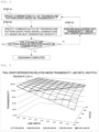
- Figure 6 illustrates a trial graph of estimation of the transmissivity T based on a thickness and a pattern shape.
- This trial graph can be drawn by using Expression (2) and its rearranged expression.
- Combinations G11 of a thickness and a pattern shape in accordance with a target transmissivity T can be specified by using such a trial graph. For example, when the transmissivity T is set to 95% or higher, a region R11 in which the transmissivity T is satisfied is specified and combinations G11 of a line width and a pitch with which the region R11 is satisfied are specified.
- the step B1 is a step of specifying a combination G12 of a thickness and a pattern shape from among the combinations G11 based on the target heat generation capacity C.
- the heat generation capacity C of the transparent heater 100 and parameters related thereto are estimated based on a thickness and a pattern shape, and a combination G12 of a thickness and a pattern shape with which a desired heat generation capacity C is satisfied is specified.
- Expression (6) above or its rearranged expression may be used. Accordingly, the transparent heater 100 having the desired heat generation capacity can be designed.
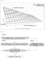
- Figure 7 illustrates a trial graph of estimation of the heat generation capacity C of the conductive pattern 130 based on the transmissivity T and the film thickness H.
- This trial graph can be drawn by using Expression (6) and its rearranged expression.
- Combinations G12 of a thickness and a pattern shape in accordance with a target heat generation capacity can be specified by using such a trial graph. For example, when the heat generation capacity is set to 15 W or larger, a region R12 on the graph is specified and combinations of the transmissivity T and the film thickness with which the region R12 is satisfied are specified. Subsequently, the combinations G12 can be further narrowed down based on constraint conditions of transparent-heater manufacturing.
- Examples of the constraint conditions of transparent-heater manufacturing comprise the relation (aspect ratio) between the line width and the film thickness, and the upper limit of the line width. These constraint conditions may be those stored in advance or may be designated by the designer through the input-output interface 330. In addition, a constraint condition in accordance with designation of a transparent-heater manufacturing method may be used.
- the line width W 1 is set to be smaller than 10 ⁇ m from a viewpoint of visibility of the conductive pattern, and when the manufacturing method is an inversion transfer printing method, (the film thickness H)/(the line width W 1 ) ⁇ 0.15 is used as a constraint condition of the aspect ratio.
- the upper and lower limits of the line width are set based on these constraint conditions.
- the transmissivity T and combinations of the line width W 1 and the pitch P with which the constraint conditions of transparent-heater manufacturing are satisfied are displayed based on a combination of the transmissivity T and the film thickness H corresponding to the point or region.
- the thermal responsiveness or the like may be displayed together.
- G12 can be specified by receiving a selection from among the combinations. At the combination selection, designation may be received from the designer through the input-output interface 330.
- step D1 when a thickness and a pattern shape can be specified with the combination G12, it is determined that designing information satisfying a desired transmissivity T and a desired heat generation capacity C is obtained, and the designing step is ended.
- step D1 loop processing that performs the steps A1 to B1 again with changed conditions may be performed.
- the loop processing is, for example, processing that changes the target transmissivity T and/or the target heat generation capacity C and executes the above-described steps A1 to B1. Moreover, even when there are a thickness and a pattern shape that can be achieved with the combination G12, an optimum thickness and an optimum pattern shape may be specified by executing the above-described processing.
- the designing processing unit 343 may execute processing of estimating the designing information DI further comprising information related to the power source capacity E 0 connected to the transparent heater 100.
- the designing processing unit 343 estimates the electric power E consumed at the resistor by Expression (7) or its rearranged expression based on the thickness and the pattern shape of the combination G12 or the heat generation capacity C considered at the step B1 and comprises the information related to the power source capacity E 0 connected to the transparent heater 100 in the designing information DI based on the electric power E.
- a method of estimating the power source capacity E 0 based on the electric power E is not particularly limited, but for example, can be estimated as the power source capacity E 0 in the range of the electric power E ⁇ 30% or ⁇ 50%. Accordingly, designing with allowance is possible with the stability of the power source taken into account.
- the processing of estimating, by the designing processing unit 343, the designing information DI further comprising information related to the power source capacity E 0 connected to the transparent heater 100 may be executed in the patterns 2 to 7 below as well.
- Figure 8 illustrates a flowchart of the designing step in the pattern 2.
- the designing step of estimating the designing information DI comprises a step A2 of specifying, by the designing processing unit 343, combinations G21 of a thickness and a pattern shape based on the heat generation capacity C, and a step B2 of specifying, by the designing processing unit 343, a combination G22 of a thickness and a pattern shape from among the combinations G21 based on the transmissivity T.
- the method of specifying G12 in the pattern 1 can be used as a method of specifying G22.
- the pattern 2 can be processed in the same manner as the pattern 1 except that the order of steps is different from that in the pattern 1.
- step D2 when a thickness and a pattern shape can be specified with the combination G22, it is determined that designing information satisfying a desired transmissivity T and a desired heat generation capacity C is obtained, and the designing step is ended.
- step D2 loop processing that performs the steps A2 to B2 again with changed conditions may be performed.
- the loop processing is, for example, processing that changes the target transmissivity T and/or the target heat generation capacity C and executes the above-described steps A2 to B2. Moreover, even when there are a thickness and a pattern shape that can be achieved with the combination G22, an optimum thickness and an optimum pattern shape may be specified by executing the above-described processing.
- the designing step of estimating the designing information DI comprises a step A3 of specifying, by the designing processing unit 343, combinations G31 of a thickness and a pattern shape based on two of the transmissivity T and the heat generation capacity C.
- the step A3 is not particularly limited as long as the step can specify combinations G31 of a thickness and a pattern shape based on two of the transmissivity T and the heat generation capacity C, but two graphs, for example, the pitch and the line width, having a common axis may be placed over and combinations G31 with which the transmissivity T and the heat generation capacity C (electric power consumption) are satisfied may be specified at once.
- the pattern 4 and the pattern 5 to be described later comprise a step of executing, by the designing processing unit 343, processing of estimating the designing information DI further based on thermal responsiveness as a target of the transparent heater 100.
- Figure 9 illustrates a flowchart of the designing step in the pattern 4.
- the designing step of estimating the designing information DI comprises a step A1 of specifying, by the designing processing unit 343, combinations G11 of a thickness and a pattern shape based on the transmissivity T, a step B1 of specifying, by the designing processing unit 343, combinations G12 of a thickness and a pattern shape from among the combinations G11 based on the heat generation capacity C, and a step C1 of specifying, by the designing processing unit 343, a combination G13 of a thickness and a pattern shape with which thermal responsiveness requested for the transparent heater is satisfied from among the combinations G12.
- the steps A1 and B1 in the pattern 4 can be processed in the same manner as in the pattern 1.
- the step C1 is a step of specifying a combination G13 of a thickness and a pattern shape with which thermal responsiveness requested for the transparent heater is satisfied from among the combinations G12.
- the "thermal responsiveness" is not particularly limited but is, for example, the balance between the heat generation capacity C and the heat releasing capacity D, and the transparent heater is designed to be more easily cooled as the heat releasing capacity D is higher when the heat generation capacity C is constant, whereas the transparent heater is designed to be less easily cooled as the heat releasing capacity D is lower when the heat generation capacity C is constant. Moreover, the transparent heater is designed to be more easily heated as the heat generation capacity C is higher when the heat releasing capacity D is constant, whereas the transparent heater is designed to be less easily heated as the heat generation capacity C is lower when the heat releasing capacity D is constant.
- An indicator of the thermal responsiveness is not particularly limited, but examples thereof comprise the heat releasing capacity D, 1/the heat releasing capacity D, the heat generation capacity C/the heat releasing capacity D, the heat releasing capacity D/the heat generation capacity C, and the heat generation capacity C - the heat releasing capacity D.
- the step C1 is a step of specifying, based on such tendencies, the combination G13 of a thickness and a pattern shape with which desired balance is obtained between the heat generation capacity C and the heat releasing capacity D.
- the heat generation capacity C expressed by Expression (6) described above or its rearranged expression and the heat releasing capacity D expressed by Expression (8) or its rearranged expression may be set, and the combination G13 may be specified so that both capacities are satisfied or the combination G13 may be specified based on the heat releasing capacity D expressed by Expression (8) or its rearranged expression since the heat generation capacity C is already considered at the step B1.
- the combination G13 of a thickness and a pattern shape with which desired thermal responsiveness is satisfied may be specified by using, as one indicator, for example, the ratio (the heat generation capacity C/the heat releasing capacity D) of the heat generation capacity C expressed by Expression (6) described above or its rearranged expression and the heat releasing capacity D expressed by Expression (7) or its rearranged expression.
- the combinations G13 can be further narrowed down based on the constraint conditions of transparent-heater manufacturing.
- the constraint conditions of transparent-heater manufacturing comprise the relation (aspect ratio) between the line width and the film thickness, and the upper limit of the line width. These constraint conditions may be those stored in advance or may be designated by the designer through the input-output interface 330.
- a constraint condition in accordance with designation of a transparent-heater manufacturing method may be used.
- the line width W 1 is set to be smaller than 10 ⁇ m from a viewpoint of visibility of the conductive pattern, and when the manufacturing method is the inversion transfer printing method, (the film thickness H)/(the line width W 1 ) ⁇ 0.15 is used as a constraint condition of the aspect ratio.
- the upper and lower limits of the line width are set based on these constraint conditions.
- the transmissivity T and combinations of the line width W 1 and the pitch P with which the constraint conditions of transparent-heater manufacturing are satisfied are displayed based on a combination of the transmissivity T and the film thickness H corresponding to the point or region.
- the thermal responsiveness or the like may be displayed together.
- G13 can be specified by receiving a selection from among the combinations. At the combination selection, designation may be received from the designer through the input-output interface 330.
- the heat generation capacity C is restricted by the power source capacity E 0 in reality as indicated by Expression (6), and thus there is an upper limit to be considered at part of the conductive pattern 130 of the transparent heater 100 other than designing.
- the heat releasing capacity is not related to the power source capacity E 0 .
- the combination G13 of a thickness and a pattern shape of the conductive thin line 140 at the step C1 there appear the range of combinations of a thickness and a pattern shape in which the heat generation capacity and the heat releasing capacity both change, and the range of combinations of a thickness and a pattern shape in which the heat generation capacity does not further increase beyond a threshold value but the heat releasing capacity changes.
- step C1 it is preferable to specify the combination G13 of a thickness and a pattern shape with which thermal responsiveness requested for the transparent heater is satisfied from among the combinations G12 while considering the power source capacity E 0 .
- the designing information DI related to the combination G13 thus specified preferably further comprises information related to the power source capacity E 0 connected to the transparent heater.
- loop processing that performs steps A1 to C1 again with changed conditions may be performed (step D1).
- a case in which no transparent heater with which a predetermined condition is satisfied can be designed means a case in which desired thermal responsiveness is achieved by adjusting the ratio (the heat generation capacity C/the heat releasing capacity D) with the power source capacity E 0 taken into account at the step C1 but the heat generation capacity C is restricted because the power source capacity E 0 is set as described above, and as a result, the heat generation capacity at the step B1 is no longer satisfied.
- Figure 10 illustrates a flowchart of the designing step in the pattern 5.
- the designing step of estimating the designing information DI comprises a step A2 of specifying, by the designing processing unit 343, combinations G21 of a thickness and a pattern shape based on the heat generation capacity C, a step B2 of specifying, by the designing processing unit 343, combinations G22 of a thickness and a pattern shape from among the combinations G21 based on the transmissivity T, and a step C2 of specifying, by the designing processing unit 343, a combination G23 of a thickness and a pattern shape with which thermal responsiveness requested for the transparent heater is satisfied from among the combinations G22.
- the steps A2 and B2 in the pattern 5 can be processed in the same manner as in the pattern 2.
- the step C2 is a step of specifying a combination G23 of a thickness and a pattern shape with which thermal responsiveness requested for the transparent heater is satisfied from among the combinations G22.
- the step C2 in the pattern 5 can be processed in the same manner as in the pattern 4.
- loop processing that performs steps A1 to C1 again with changed conditions may be performed (step D2).
- a case in which no transparent heater with which a predetermined condition is satisfied can be designed means a case in which desired thermal responsiveness is achieved by adjusting the ratio (the heat generation capacity C/the heat releasing capacity D) with the power source capacity E 0 taken into account at the step C1 but the heat generation capacity C is restricted because the power source capacity E 0 is set as described above, and as a result, the heat generation capacity at the step A1 is no longer satisfied.
- the pattern 6 is a pattern in which, instead of specifying combinations G21 based on the heat generation capacity C as a target in the pattern 5, the power source capacity E 0 connected to the transparent heater 100 is assumed and combinations G31 of a thickness and a pattern shape are specified by using the power source capacity E 0 in place of the heat generation capacity C.
- the heat generation capacity C is more specifically assumed as the power source capacity E 0 , and in this meaning, the pattern 6 corresponds to a lower-level concept of the pattern 5.
- Figure 11 illustrates a flowchart of the designing step in the pattern 6.
- the designing step of estimating the designing information DI comprises a step A3 of specifying, by the designing processing unit 343, combinations G31 of a thickness and a pattern shape based on the power source capacity E 0 connected to the transparent heater 100, a step B3 of specifying, by the designing processing unit 343, combinations G32 of a thickness and a pattern shape from among the combinations G31 based on the transmissivity T, and a step C3 of specifying, by the designing processing unit 343, a combination G33 of a thickness and a pattern shape of the conductive thin line from among the combinations G32 in accordance with thermal responsiveness as a target of the transparent heater.
- the step A3 is a step of specifying combinations G31 of a thickness and a pattern shape based on the power source capacity E 0 connected to the transparent heater.
- the electric power E consumed at the resistor of the conductive pattern 130 is estimated based on a thickness and a pattern shape, and the electric power E and the power source capacity E 0 are compared to specify combinations G31 of a thickness and a pattern shape with which the power source capacity E 0 can be effectively used. Accordingly, it is possible to specify combinations G31 of a thickness and a pattern shape with which the electric power E is not excessively larger than the power source capacity E 0 nor the electric power E is not excessively smaller than the power source capacity E 0 .
- Combinations G31 of a thickness and a pattern shape can be specified based on the power source capacity E 0 by using, for example, the trial graph as illustrated in Figure 7 .
- the power source capacity E 0 is 7.5 W
- the region R12 for which the electric power E is 5 to 10 W is specified and combinations G31 of a line width and a pitch with which the region R12 is satisfied are specified.
- the electric power E may have a value range such as 70 to 130%, 80 to 120%, or 90 to 110% of the power source capacity E 0 as a reference.
- the electric power E is designed to have a width in this manner, it is easier to define a thickness and a pattern shape in accordance with thermal responsiveness at a step to be described later.
- the heat releasing capacity can be improved although the heat generation capacity is not improved.
- the transparent property can be further improved.
- the step B3 is a step of specifying combinations G32 of a thickness and a pattern shape with which, for example, the transmissivity T is equal to or larger than a predetermined value from among the combinations G31.
- the transmissivity T of the conductive pattern 130 is estimated based on a thickness and a pattern shape, and combinations G32 of a thickness and a pattern shape with which a desired transmissivity T is satisfied are specified. Accordingly, the transparent heater 100 having a desired transparent property can be designed.
- Combinations G32 of a thickness and a pattern shape in accordance with a target transmissivity T can be specified from among the combinations G31 by using, for example, the trial graph as illustrated in Figure 6 .
- the transmissivity T is set to 95% or higher, a region R11 in which the transmissivity T is satisfied is specified and combinations G32 of a line width and a pitch with which the region R11 is satisfied are specified.
- the step C3 is a step of specifying a combination G33 of a thickness and a pattern shape of the conductive thin line 140 from among the combinations G32 in accordance with thermal responsiveness as a target of the transparent heater.
- the step C2 in the pattern 5 can be processed in the same manner as in the pattern 5.
- the pattern 7 is a pattern in which, instead of specifying combinations G12 based on the heat generation capacity C as a target in the pattern 4, the power source capacity E 0 connected to the transparent heater 100 is assumed and combinations G32 of a thickness and a pattern shape are specified by using the power source capacity E 0 in place of the heat generation capacity C.
- the heat generation capacity C is more specifically assumed as the power source capacity E 0 , and in this meaning, the pattern 7 corresponds to a lower-level concept of the pattern 4.
- Figure 12 illustrates a flowchart of the designing step in the pattern 7.
- the designing step of estimating the designing information DI comprises a step A4 of specifying, by the designing processing unit 343, combinations G41 of a thickness and a pattern shape based on the transmissivity T, a step B4 of specifying, by the designing processing unit 343, combinations G42 of a thickness and a pattern shape from among the combinations G41 based on the power source capacity E 0 connected to the transparent heater 100, and a step C4 of specifying, by the designing processing unit 343, a combination G43 of a thickness and a pattern shape of the conductive thin line from among the combinations G42 in accordance with thermal responsiveness as a target of the transparent heater.
- the step A4 is a step corresponding to the above-described step B3 and is a step of specifying combinations G41 of a thickness and a pattern shape with which, for example, the transmissivity T is equal to or larger than a predetermined value.
- the transmissivity T of the conductive pattern 130 is estimated based on a thickness and a pattern shape, and combinations G42 of a thickness and a pattern shape with which a desired transmissivity T is satisfied are specified. Accordingly, the transparent heater 100 having a desired transparent property can be designed.
- the step B4 is a step corresponding to the above-described step A3 and is a step of specifying combinations G42 of a thickness and a pattern shape from among the combinations G41 based on the power source capacity E 0 connected to the transparent heater 100.
- the electric power E consumed at the resistor of the conductive pattern 130 is estimated based on a thickness and a pattern shape, and the electric power E and the power source capacity E 0 are compared to specify combinations G42 of a thickness and a pattern shape with which the power source capacity E 0 can be effectively used. Accordingly, it is possible to specify combinations G42 of a thickness and a pattern shape with which the electric power E is not excessively larger than the power source capacity E 0 nor the electric power E is not excessively smaller than the power source capacity E 0 .
- the step C4 is a step corresponding to the above-described step C3 and is a step of specifying a combination G43 of a thickness and a pattern shape of the conductive thin line 140 from among the combinations G42 in accordance with thermal responsiveness as a target of the transparent heater.
- the loop processing is processing that changes the aspect ratio or height of the conductive thin line comprised in the conductive pattern and executes the steps A3 to C3 or A4 to C4, processing that changes the power source capacity E 0 and executes the steps A3 to C3 or A4 to C4, or processing that changes the transmissivity T and executes the steps A3 to C3 or A4 to C4.
- an optimum thickness and an optimum pattern shape may be specified by executing the above-described processing.
- the transparent-heater designing method it is possible to obtain the designing information of the conductive pattern with the transparent property, the heat generation capacity, and the heat releasing capacity taken into account.
- the display control unit 344 executes processing that controls display of the designing information DI on the display device.
- the display control of the designing information DI is not limited to a particular aspect, but for example, information related to the thickness of each conductive thin line 140 and information related to the pattern shape PAT of the conductive pattern 130 may be displayed by text or may be displayed as two-dimensional or three-dimensional graphs as illustrated in Figures 6 and 7 . In the case of graph display, a region representing a desired transmissivity T and/or a desired heat generation capacity C may be highlighted as illustrated in Figures 6 and 7 .
- the display control unit 344 may control the display device to display indicating that the designing information DI cannot be specified.
- the display control unit 344 may control display of the adjacent designing information DI' in addition to the designing information DI on the display device, the adjacent designing information DI' being estimated based on the transmissivity T' and the heat generation capacity C' adjacent to the transmissivity T and the heat generation capacity C as targets.
- the display control of the adjacent designing information DI' estimated based on the transmissivity T' and the heat generation capacity C' the designing information when the transmissivity is increased or decreased can be understood as reference information and designing can be easily performed.
- the designing processing unit 343 may execute a data transmission step of transmitting the designing information DI to the mask manufacturing device, the plate manufacturing device, or the conductive pattern formation device. Accordingly, manufacturing of the transparent heater can be executed by using the designing information DI.
- a program configured to cause the above-described information processing device to execute the above-described designing method, a recording medium in which the program is recorded, and an information processing device configured to execute the above-described designing method may be provided.
- the information processing device of the present embodiment may be a server configured to execute the above-described designing method in accordance with a request from the terminal and transmit information related to designing of the conductive pattern to the terminal.
- the mask manufacturing method of the present embodiment comprises a process of manufacturing, by the mask manufacturing device, a mask based on the designing information DI obtained by the above-described transparent-heater designing method.
- the manufactured mask may be, for example, a photomask.
- a specific mask manufacturing method is not particularly limited but is, for example, a method of forming a pattern on a photomask substrate based on the designing information DI by electron beam drawing or the like.
- the plate manufacturing method of the present embodiment comprises a process of manufacturing, by the plate manufacturing device, a plate based on the designing information DI obtained by the above-described transparent-heater designing method.
- the plate is, for example, a flat plate or a cylinder plate.
- a specific plate manufacturing method is not particularly limited, but for example, a pattern based on the designing information DI may be transferred onto the plate by photolithography using the mask obtained by the above-described mask manufacturing method, or a pattern based on the designing information DI may be directly formed on the plate by electron beam drawing or the like.
- the transparent-heater manufacturing method of the present embodiment comprises a process of forming, by the conductive pattern formation device, the conductive pattern based on the designing information DI obtained by the above-described transparent-heater designing method and manufacturing the transparent heater.
- the transparent-heater manufacturing method is, for example, a method of performing plate printing of the conductive pattern on the transparent base material by using the plate obtained as described above, a method of forming the conductive pattern on the transparent base material by photolithography using the mask, or a method of forming the conductive pattern on the transparent base material by using the ink-jet method. Each method will be simply described below.
- the plate printing method comprises a mask manufacturing step of manufacturing, by the mask manufacturing device, a mask based on the designing information DI obtained by the above-described transparent-heater designing method, a plate manufacturing step of manufacturing, by the mask manufacturing device, a plate by using the mask, and a heater manufacturing step of forming, by the mask manufacturing device, the conductive pattern on the transparent base material by the plate printing method using the plate and manufacturing the transparent heater, and in the heater manufacturing step, the film thickness of the conductive pattern is controlled based on the designing information DI to manufacture the transparent heater.
- the plate manufacturing device may directly manufacture the plate without using the mask in place of the plate manufacturing step of manufacturing the plate by using the mask. More specifically, as described above, the plate manufacturing device may produce the plate based on the designing information DI by electron beam drawing or the like.
- the method of forming the conductive pattern on the transparent base material by the plate printing method is not particularly limited, but for example, ink containing metal particles is transferred onto the transparent base material by the inversion transfer printing method using the plate, and the ink transferred onto the transparent base material is sintered to form the conductive thin lines.
- the film thickness of the conductive pattern can be controlled based on the designing information DI by a printing device used for the plate printing method in the heater manufacturing step. More specifically, the printing device can control the film thickness of the conductive pattern by adjusting the amount of ink applied to the plate based on the designing information DI. Moreover, in the plate manufacturing step, the film thickness of the conductive pattern can be controlled by controlling the depth of the plate based on the designing information DI.
- the photolithography method comprises a mask manufacturing step of manufacturing, by the mask manufacturing device, a mask based on the designing information DI obtained by the above-described transparent-heater designing method, and a heater manufacturing step of forming, by the mask manufacturing device, the conductive pattern on the transparent base material by the photolithography method using the mask and manufacturing the transparent heater, and in the heater manufacturing step, the film thickness of the conductive pattern is controlled based on the designing information DI to manufacture the transparent heater.
- a metal film is uniformly formed on the transparent base material, a photosensitive material is applied thereon, the metal film at any unnecessary place is removed through development after exposure by using the above-described mask, and accordingly, the conductive thin lines are formed.
- a device configured to execute the photolithography method may control the film thickness of the conductive pattern based on the designing information DI in the heater manufacturing step. More specifically, the film thickness of the conductive pattern can be controlled by controlling the thickness of the metal film, a development condition, and the like based on the designing information DI.
- the ink-jet method comprises a heater manufacturing step of forming, by the printing device, the conductive pattern on the transparent base material based on the designing information DI obtained by the above-described transparent-heater designing method and manufacturing the transparent heater, and accordingly, the transparent heater is manufactured.
- the shape of a thin line pattern and the film thickness can be optionally adjusted by forming the conductive pattern based on the designing information DI.
- the transparent heater obtained by the designing method of the present embodiment is, for example, a transparent heater connected to a power source of the power source capacity E 0 and comprises a transparent base material and a heater unit comprising a conductive pattern formed on a surface of or inside the transparent base material, the conductive pattern has the electric power consumption E in the range of ⁇ 30% of the power source capacity E 0 , and the transmissivity T is equal to or higher than 75%. Furthermore, the visibility of the conductive pattern is preferably low, and the line width is preferably 10 ⁇ m or smaller.
- the obtained transparent heater can achieve a desired transparent property, a desired heat generation capacity, and a desired heat releasing capacity and also achieve desired heat response performance.
- the obtained transparent heater can have an improved heat releasing capacity when the conductive pattern has the electric power consumption E in the range of 100 to 130% of the power source capacity E 0 , and the obtained transparent heater can have an improved heat releasing capacity when the conductive pattern has the electric power consumption E in the range of 70 to 100% of the power source capacity E 0 .
- preferable ranges of parameters will be described in detail on a premise that the above-described configuration is satisfied.
- Transparent in the transparent base material 110 means that the visible light transmissivity is preferably equal to or higher than 80%, more preferably equal to or higher than 90%, further more preferably equal to or higher than 95%.
- the visible light transmissivity can be measured in compliance with JIS R 3106:1998.
- the material of the transparent base material 110 is not particularly limited but is, for example, a transparent inorganic base material such as glass, or a transparent organic base material such as acrylate ester, methacrylate ester, polyethylene terephthalate, polybutylene terephthalate, polyethylene naphthalate, polycarbonate, polyarylate, polyvinyl chloride, polyethylene, polypropylene, polystyrene, nylon, aromatic polyamide, polyetheretherketone, polysulfone, polyether sulfone, polyimide, or poly ether imide.
- polyethylene terephthalate is preferable from a viewpoint of cost.
- Polyimide is preferable from a viewpoint of thermal resistance.
- Polyethylene terephthalate and polyethylene naphthalate are preferable from a viewpoint of close contact to the conductive thin lines.
- the transparent base material 110 may be made of one kind of material or may be a stack of two or more kinds of material.
- organic base materials or inorganic base materials may be stacked or organic base materials and inorganic base materials may be stacked.
- the film thickness of the transparent base material 110 is preferably 5 to 500 ⁇ m, more preferably 10 to 100 ⁇ m.
- the heater unit 120 comprises the conductive pattern 130.
- the conductive pattern 130 comprised in the heater unit 120 is, for example, a pattern constituted by the conductive thin lines 140.
- the conductive pattern 130 is electrically connected to the power source 150 through the electrodes (not illustrated), and the conductive pattern 130 generates heat and the transparent heater 100 exerts a heater function as current flows from the power source 150 to the conductive pattern.
- the conductive pattern 130 may be a grid pattern (mesh pattern) in which the conductive thin lines 140 intersect as illustrated in Figure 1 or may be a line pattern.
- the unit shape of the grid formed of the conductive thin lines 140 is not particularly limited but is, for example, a triangle, a rectangle, or a hexagon.
- the conductive thin lines 140 are not limited to straight lines but may be curved lines or wavy lines.
- the pitches P 1 and P 2 of the conductive pattern 130 are preferably 5 to 1000 ⁇ m, more preferably 50 to 500 ⁇ m, further more preferably 100 to 250 ⁇ m.
- the pitches P 1 and P 2 of the conductive pattern 130 are in any of the above-described ranges, the balance among the transparent property, the heat generation capacity, and the heat releasing capacity of the heater unit 120 tends to further improve.
- the pitch P 1 or P 2 means the sum of the line width W 21 or W 22 and the distance between the conductive thin lines 140.
- the pitches P 1 and P 2 are equal, but when the conductive pattern 130 is a rectangular or rhombic grid pattern, the pitches P 1 and P 2 of the conductive thin lines 140 in two intersecting directions are preferably restricted to any of the above-described ranges.
- the opening widths W 21 and W 22 of each opening part 141 surrounded by the conductive thin lines 140 are preferably 40 to 2000 ⁇ m, more preferably 50 to 1500 ⁇ m, further more preferably 60 to 1000 ⁇ m.
- the opening widths W 21 and W 22 are in any of the above-described ranges, the balance among the transparent property, the heat generation capacity, and the heat releasing capacity of the heater unit 120 tends to further improve.
- the opening widths W 21 and W 22 are equal, but when the conductive pattern 130 is a rectangular or rhombic grid pattern, the opening widths W 21 and W 22 of the conductive thin lines 140 in two intersecting directions are preferably restricted to any of the above-described ranges.
- the conductive pattern may be expressed by using opening part area So and an opening ratio OR per opening part 141 in place of or in addition to the opening widths W 21 and W 22 and the pitches P 1 and P 2 .
- the opening part area So is preferably 1600 ⁇ m 2 to 4.00 mm 2 , more preferably 2500 ⁇ m 2 to 2.25 mm 2 , further more preferably 3600 ⁇ m 2 to 1.00 mm 2 .
- each opening part preferably satisfies any of the above-described ranges.
- the opening ratio OR is preferably 80 to 99.9 area%, more preferably 85 to 99.8 area%, further more preferably 90 to 99.6 area%, still further more preferably 95 to 99.5 area%.
- Each conductive thin line 140 is preferably a thin line containing metal.
- the metal is not particularly limited but is, for example, gold, silver, copper, or aluminum. Among these metals, silver or copper is preferable, and copper is more preferable.
- the line widths W 11 and W 12 of each conductive thin line 140 are preferably 0.25 to 10 ⁇ m, more preferably 0.5 to 7.5 ⁇ m, further more preferably 1.0 to 5.0 ⁇ m.
- the line widths W 11 and W 12 of each conductive thin line 140 are 10 ⁇ m or smaller, the visibility of the conductive thin line 140 decreases and the transparent property of the heater unit 120 tends to further improve.
- the line widths W 11 and W 12 of each conductive thin line 140 are 0.25 ⁇ m or larger, the heat generation capacity and the heat releasing capacity tend to further improve. In particular, the heat releasing capacity tends to become larger than the heat generation capacity as the line widths W 11 and W 12 of each conductive thin line 140 increase.
- the film thickness H of each conductive thin line 140 is preferably 12.5 to 10000 nm, more preferably 40 to 6750 nm, further more preferably 100 to 4000 nm.
- the film thickness H of each conductive thin line 140 is equal to or smaller than 1000 nm, the visibility tends to decrease at a wide view angle.
- the film thickness H of each conductive thin line 140 is equal to or larger than 10 nm, the heat generation capacity and the heat releasing capacity tend to further improve. In particular, the heat releasing capacity tends to become larger than the heat generation capacity as the film thickness H of each conductive thin line 140 increases.
- the aspect ratio (H/W 1 ) expressed by the film thickness H relative to the line width W 1 of each conductive thin line 140 is preferably 0.05 to 1.00, more preferably 0.08 to 0.90, further more preferably 0.10 to 0.80.
- the aspect ratio of each conductive thin line 140 is in any of the above-described ranges, the balance among the transparent property, the heat generation capacity, and the heat releasing capacity of the heater unit 120 tends to further improve.
- the transmissivity T of the heater unit 120 is preferably 75 to 99.9%, more preferably 80 to 99.8%, further more preferably 85 to 99.6%, still further more preferably 90 to 99.5%.
- the transmissivity in the present embodiment means the visible light transmissivity and can be measured by estimating the transmissivity in the range of visible light (360 to 830 nm) in compliance with the total light transmissivity of JIS K 7361-1:1997.
- the transmissivity T of the heater unit 120 tends to further improve as the line width of the conductive pattern 130 is reduced or the opening ratio is improved.
- the sheet resistivity Rs of the conductive pattern 130 is preferably 0.1 to 1000 ⁇ /sq, more preferably 0.1 to 500 ⁇ /sq, further more preferably 0.1 to 300 ⁇ /sq, still further more preferably 0.1 to 200 ⁇ /sq, still further more preferably 0.1 to 100 ⁇ /sq, still further more preferably 0.1 to 20 ⁇ /sq, still further more preferably 0.1 to 10 ⁇ /sq.
- the sheet resistivity Rs is in any of the above-described ranges, the balance between the heat generation capacity and the heat releasing capacity of the heater unit 120 tends to further improve.
- a part where the conductive pattern 130 is disposed on the entire surface is cut in a rectangular shape out of the heater unit 120 to obtain a measurement sample.
- the sheet resistivity Rs ( ⁇ /sq) can be measured from the obtained measurement sample by a four-terminal method compliant with JIS K 7194:1994.
- a resistivity meter used to measure the sheet resistivity is, for example, "Loresta GP" (product name; manufactured by Mitsubishi Chemical Corporation).
- the sheet resistivity Rs tends to decrease as the aspect ratio (film thickness) increases even at the same occupation area rate of the conductive thin lines.
- the sheet resistivity Rs can be adjusted through selection of the kind of a metallic material of which the conductive thin lines are made.
- Trial graph data as exemplarily illustrated in Figures 6 and 7 was established, and a program that can process the steps of the designing method illustrated in Figure 10 was produced and installed on a personal computer.
- Transparent base material polyethylene terephthalate film
- Example 1 Line width Pitch Opening ratio Transmissivity Sheet resistivity A4 resistance value Electric power consumed at resistor Heat generation capacity of Heater w [ ⁇ m] P [ ⁇ m] X T.T [ ⁇ / ⁇ ] [ ⁇ ] [W] [W]
- Example 1 1.00 60 0.97 0.89 18.00 25.46 0.98 0.98
- Example 2 2.00 60 0.93 0.86 4.50 6.36 3.93 3.93
- Example 3 3.00 60 0.90 0.83 2.00 2.83 8.84 5.00
- Example 4 5.00 150 0.93 0.86 1.80 2.55 9.82 5.00
- Example 5 80 0.93 0.85 2.67 3.77 6.63 5.00
- Example 6 8.00 100 0.85 0.78 0.47 0.66 37.71 5.00
- Example 7 1.00 99.5 0.98 0.90 29.85 42.22 0.59 0.59
- Example 8 0.25 6 0.92 0.84 28.80 40.73 0.61 0.61
- Example 9 3.00 60 0.90 0.83 2.00 2.83 8.84 5.00
- Example 10 3.00 100 0.94 0.87 3.33 4.71 5.30
- Table 2 lists results of estimating the heat capacity of the transparent heater when configured as a transparent heater of the A4 size (297 mm ⁇ 210 mm) and the amount of heat necessary for temperature increase and estimating a temperature increase time based on the heat generation capacity of the heater.
- Example 1 0.50 19.84 0.98 20.20
- Example 2 0.50 19.97 3.93 5.08
- Example 3 0.50 20.18 5.00 4.04
- Example 5 0.50 20.08 5.00 4.02
- Example 6 0.54 21.44 5.00 4.29
- Example 7 0.50 19.82 0.59 33.47
- Example 8 0.50 19.82 0.61 32.30
- Example 9 0.50 20.18 5.00 4.04
- Example 10 0.50 20.03 5.00 4.01
- Example 11 0.51 20.44 5.00 4.09
- Example 12 0.51 20.21 5.00 4.04
- Example 13 0.51 20.21 5.00 4.04
- Example 14 0.52 20.72 5.00 4.14
- Example 15 0.50 19.89 2.12 9.38
- Example 16 0.56 22.36 5.00 4.47
- Example 17 0.51 20.26 5.00 4.05
- the designing processing was performed to design a transparent heater having thermal responsiveness with the temperature increase time of 4.5 seconds or shorter and a transparent property with the transmissivity of 85% or higher.
- combinations G33 of a thickness and a pattern shape, comprising examples 4, 5, 10, and 13 were specified.
- a transparent heater of the present invention has industrial applicability as a heater bonded to a target having a transparent property or a heater that does not impair design of a non-bonding target.
Landscapes
- Engineering & Computer Science (AREA)
- Manufacturing & Machinery (AREA)
- Microelectronics & Electronic Packaging (AREA)
- Surface Heating Bodies (AREA)
Applications Claiming Priority (2)
| Application Number | Priority Date | Filing Date | Title |
|---|---|---|---|
| JP2020146006 | 2020-08-31 | ||
| PCT/JP2021/031693 WO2022045331A1 (ja) | 2020-08-31 | 2021-08-30 | 透明ヒータ及びその設計方法 |
Publications (2)
| Publication Number | Publication Date |
|---|---|
| EP4207941A1 true EP4207941A1 (de) | 2023-07-05 |
| EP4207941A4 EP4207941A4 (de) | 2024-03-27 |
Family
ID=80353455
Family Applications (1)
| Application Number | Title | Priority Date | Filing Date |
|---|---|---|---|
| EP21861752.0A Pending EP4207941A4 (de) | 2020-08-31 | 2021-08-30 | Transparente heizung und entwurfsverfahren dafür |
Country Status (5)
| Country | Link |
|---|---|
| US (1) | US20230232539A1 (de) |
| EP (1) | EP4207941A4 (de) |
| JP (1) | JP7489471B2 (de) |
| CN (1) | CN116097906A (de) |
| WO (1) | WO2022045331A1 (de) |
Families Citing this family (1)
| Publication number | Priority date | Publication date | Assignee | Title |
|---|---|---|---|---|
| US12557185B2 (en) | 2022-07-27 | 2026-02-17 | Applied Materials, Inc. | Transparent heaters for improved epitaxy reactor productivity |
Family Cites Families (13)
| Publication number | Priority date | Publication date | Assignee | Title |
|---|---|---|---|---|
| JPH02165591A (ja) * | 1988-12-20 | 1990-06-26 | Nippon Sheet Glass Co Ltd | 自動車窓用ヒータ線の導体印刷パターン作図装置 |
| WO1994005524A1 (en) * | 1992-09-03 | 1994-03-17 | Ristance Corporation | Defrostable-defoggable window and method of manufacture |
| DE102006002636B4 (de) * | 2006-01-19 | 2009-10-22 | Saint-Gobain Sekurit Deutschland Gmbh & Co. Kg | Tansparente Scheibe mit einem beheizbaren Schichtsystem |
| JP2008123784A (ja) | 2006-11-10 | 2008-05-29 | Kitagawa Ind Co Ltd | フィルムヒーター |
| JP2010251230A (ja) | 2009-04-20 | 2010-11-04 | Fujifilm Corp | 電熱窓ガラス |
| JP5410353B2 (ja) * | 2010-03-31 | 2014-02-05 | 富士フイルム株式会社 | 透明導電膜の製造方法、導電性フイルム、透明発熱体及びプログラム |
| JP5548051B2 (ja) | 2010-06-30 | 2014-07-16 | 富士フイルム株式会社 | 透明導電性フイルム及び発熱ガラスの製造方法 |
| WO2014034920A1 (ja) * | 2012-09-03 | 2014-03-06 | コニカミノルタ株式会社 | 透明電極およびその製造方法ならびに有機電子デバイス |
| JP2014218103A (ja) * | 2013-05-02 | 2014-11-20 | 株式会社レニアス | 発熱層を有する車両用樹脂ガラスとその製造方法 |
| JP6668703B2 (ja) | 2015-11-24 | 2020-03-18 | 株式会社デンソー | 透明ヒータ |
| JP6770702B2 (ja) | 2016-05-23 | 2020-10-21 | 大日本印刷株式会社 | 導電性発熱体、合わせガラスおよび乗物 |
| CN109478445B (zh) * | 2016-07-12 | 2021-07-20 | 大日本印刷株式会社 | 图案化导电体、带导电体的片、发热板、交通工具和图案化导电体的制造方法 |
| US10582571B2 (en) * | 2016-09-06 | 2020-03-03 | Eastman Kodak Company | Printed transparent heaters using embedded micro-wires |
-
2021
- 2021-08-30 WO PCT/JP2021/031693 patent/WO2022045331A1/ja not_active Ceased
- 2021-08-30 CN CN202180053718.5A patent/CN116097906A/zh not_active Withdrawn
- 2021-08-30 JP JP2022545754A patent/JP7489471B2/ja active Active
- 2021-08-30 US US18/023,457 patent/US20230232539A1/en active Pending
- 2021-08-30 EP EP21861752.0A patent/EP4207941A4/de active Pending
Also Published As
| Publication number | Publication date |
|---|---|
| JP7489471B2 (ja) | 2024-05-23 |
| US20230232539A1 (en) | 2023-07-20 |
| CN116097906A (zh) | 2023-05-09 |
| EP4207941A4 (de) | 2024-03-27 |
| JPWO2022045331A1 (de) | 2022-03-03 |
| WO2022045331A1 (ja) | 2022-03-03 |
Similar Documents
| Publication | Publication Date | Title |
|---|---|---|
| JP7356046B2 (ja) | 異方導電性フィルム及び接続構造体 | |
| US20220357808A1 (en) | Touch screen sensor | |
| CN103282866B (zh) | 触控面板 | |
| US7849424B2 (en) | Systems, devices, and methods for controlling electrical and optical properties of transparent conductors | |
| KR101641761B1 (ko) | 도전 시트 및 터치 패널 | |
| CN103649890B (zh) | 导电片与触控面板 | |
| CN103380411B (zh) | 导电片和触控面板 | |
| EP3570152A1 (de) | Leitfähige folie und berührungstafel | |
| US10664118B2 (en) | Conductive film and touch panel | |
| US9137893B2 (en) | Micro-wire electrode buss | |
| US9167688B2 (en) | Micro-wire pattern for electrode connection | |
| EP4207941A1 (de) | Transparente heizung und entwurfsverfahren dafür | |
| US20140209355A1 (en) | Large-current micro-wire pattern | |
| KR101867972B1 (ko) | 광투과성 도전재료 | |
| US20180341349A1 (en) | Optically transparent electroconductive material | |
| US9131606B2 (en) | Micro-channel pattern for effective ink distribution | |
| CN107003760A (zh) | 光透导电材料 | |
| JP2019101981A (ja) | 光透過性導電材料 | |
| CN114815422B (zh) | 显示面板及其制造方法 | |
| JP2023163367A (ja) | 発熱部材 | |
| JP2015049688A (ja) | 導電シート及びタッチパネル | |
| WO2014208374A1 (ja) | 銀導電膜の製造方法 | |
| JP2019105955A (ja) | 光透過性導電材料 | |
| WO2019059025A1 (ja) | 光透過性導電材料 | |
| HK1246509B (zh) | 各向异性导电性膜及连接构造体 |
Legal Events
| Date | Code | Title | Description |
|---|---|---|---|
| STAA | Information on the status of an ep patent application or granted ep patent |
Free format text: STATUS: THE INTERNATIONAL PUBLICATION HAS BEEN MADE |
|
| PUAI | Public reference made under article 153(3) epc to a published international application that has entered the european phase |
Free format text: ORIGINAL CODE: 0009012 |
|
| STAA | Information on the status of an ep patent application or granted ep patent |
Free format text: STATUS: REQUEST FOR EXAMINATION WAS MADE |
|
| 17P | Request for examination filed |
Effective date: 20230228 |
|
| AK | Designated contracting states |
Kind code of ref document: A1 Designated state(s): AL AT BE BG CH CY CZ DE DK EE ES FI FR GB GR HR HU IE IS IT LI LT LU LV MC MK MT NL NO PL PT RO RS SE SI SK SM TR |
|
| DAV | Request for validation of the european patent (deleted) | ||
| DAX | Request for extension of the european patent (deleted) | ||
| STAA | Information on the status of an ep patent application or granted ep patent |
Free format text: STATUS: EXAMINATION IS IN PROGRESS |
|
| A4 | Supplementary search report drawn up and despatched |
Effective date: 20240228 |
|
| RIC1 | Information provided on ipc code assigned before grant |
Ipc: B32B 15/02 20060101ALI20240222BHEP Ipc: H05B 3/84 20060101ALI20240222BHEP Ipc: H05B 3/20 20060101AFI20240222BHEP |
|
| 17Q | First examination report despatched |
Effective date: 20240312 |
|
| STAA | Information on the status of an ep patent application or granted ep patent |
Free format text: STATUS: THE APPLICATION IS DEEMED TO BE WITHDRAWN |