EP4208014B1 - Dispositif de traite - Google Patents
Dispositif de traite Download PDFInfo
- Publication number
- EP4208014B1 EP4208014B1 EP21798767.6A EP21798767A EP4208014B1 EP 4208014 B1 EP4208014 B1 EP 4208014B1 EP 21798767 A EP21798767 A EP 21798767A EP 4208014 B1 EP4208014 B1 EP 4208014B1
- Authority
- EP
- European Patent Office
- Prior art keywords
- milk
- filter
- cleaning liquid
- milking
- pulse
- Prior art date
- Legal status (The legal status is an assumption and is not a legal conclusion. Google has not performed a legal analysis and makes no representation as to the accuracy of the status listed.)
- Active
Links
Images

Classifications
-
- A—HUMAN NECESSITIES
- A01—AGRICULTURE; FORESTRY; ANIMAL HUSBANDRY; HUNTING; TRAPPING; FISHING
- A01J—MANUFACTURE OF DAIRY PRODUCTS
- A01J9/00—Milk receptacles
- A01J9/02—Milk receptacles with straining or filtering devices
-
- A—HUMAN NECESSITIES
- A01—AGRICULTURE; FORESTRY; ANIMAL HUSBANDRY; HUNTING; TRAPPING; FISHING
- A01J—MANUFACTURE OF DAIRY PRODUCTS
- A01J7/00—Accessories for milking machines or devices
- A01J7/02—Accessories for milking machines or devices for cleaning or sanitising milking machines or devices
- A01J7/022—Clean-in-Place Systems, i.e. CIP, for cleaning the complete milking installation in place
-
- A—HUMAN NECESSITIES
- A01—AGRICULTURE; FORESTRY; ANIMAL HUSBANDRY; HUNTING; TRAPPING; FISHING
- A01J—MANUFACTURE OF DAIRY PRODUCTS
- A01J11/00—Apparatus for treating milk
- A01J11/06—Strainers or filters for milk
-
- A—HUMAN NECESSITIES
- A01—AGRICULTURE; FORESTRY; ANIMAL HUSBANDRY; HUNTING; TRAPPING; FISHING
- A01J—MANUFACTURE OF DAIRY PRODUCTS
- A01J5/00—Milking machines or devices
- A01J5/007—Monitoring milking processes; Control or regulation of milking machines
Definitions
- the invention relates to a milking device for milking a dairy animal, and provided with milking means, a control unit for the milking device, a milk line for transporting the milk from the milking means to a milk tank, a milk filter for filtering the milk passing through the milk line, and a cleaning device for cleaning the milk filter with a cleaning liquid
- the milk filter comprises a housing which surrounds a filter volume and which comprises a milk inlet part with a milk inlet, a milk outlet part with a milk outlet and a circumferential outer wall in between, wherein the milk filter is configured to be flushed, in use, in a first direction with the milk to be filtered, which first direction runs from the milk inlet to the milk outlet, wherein the cleaning device is configured to clean the milk filter by passing cleaning liquid through the milk filter in a countercurrent direction opposite to the first direction.
- Milking dairy animals requires the milked milk to be filtered.
- dirt such as manure and bedding particles, hairs, but also small cell clusters and flakes and the like, are filtered from the milk before it is passed to the milk tank. Over the course of time, the filter will become very soiled.
- filter sleeves have been used, which were replaced at least three times a day.
- NL C 1037403 discloses a milking device with a stainless steel milk filter which can be cleaned by means of countercurrent cleaning. As a result thereof, the filter can continue to be used without having to be replaced. In this way, the labor-intensive replacement of the filter sleeves and the excessive use of base materials can already be prevented in an efficient manner. No further details regarding any aspect of the milk filter are given in this case.
- Document NL8102764 discloses a milking device according to the preamble of claim 1.
- the invention provides a milking device according to claim 1, in particular a milking device for milking a dairy animal, and provided with milking means, a control unit for the milking device, a milk line for transporting the milk from the milking means to a milk tank, a milk filter for filtering the milk passing through the milk line, and a cleaning device for cleaning the milk filter with cleaning liquid
- the milk filter comprises a housing which surrounds a filter volume, and which comprises a milk inlet part with a milk inlet, a milk outlet part with a milk outlet, and a circumferential outer wall in between, a filter component which is provided in the filter volume and comprises a circumferential plate part comprising a plurality of filter holes, and which divides the filter volume into a central inner filter volume which is connected to one of the milk inlet and the milk outlet, and an outer filter volume surrounding the latter, and connected to the other one of the milk inlet and the milk outlet, wherein the milk filter is configured to be flushed, in use, in a
- the Applicant presumes that the cleanability of, in particular, the filter is improved by the invention due to the fact that the amount of liquid collected in the filter volume, due to its non-compressibility, forms a kind of wall which the cleaning liquid of the next pulse hits. This collision creates additional turbulence resulting in a greater turbulence intensity in the liquid, both in the top layer of the formed layer of liquid and in the new cleaning liquid which collides with it. These turbulences result in improved cleaning action, in particular at the location of these turbulences.
- the plurality of filter holes does not extend in a perpendicular plane to the force of gravity. This is due to the fact that otherwise all holes will either be situated under the liquid level or be situated above, which is disadvantageous for the cleaning action, inter alia because the liquid is then unable to arrange itself efficiently with respect to the holes of the filter component.
- the plurality of holes will often extend in a vertical plane, at least a surface which comprises a vertical.
- the liquid level is situated in an upper half of the plurality of holes, in particular during at least part of the second pulse stage.
- the upper holes were most soiled and (partly as a result thereof) most difficult to clean.
- the cleaning device is configured to change the liquid level from pulse to pulse, in particular to raise it from pulse to pulse.
- This increases the proportion of holes which are cleaned very thoroughly, as the greater turbulence at the location of these holes causes greater fluctuations in speed and thus in the local wall sheer stress. In this way, it is in principle possible to clean the entire filter component more thoroughly.
- the liquid level does not have to be changed between every two pulses. Thus, it is for example also possible to maintain the same liquid level for two or more pulses before changing the liquid level. It is also possible to change the liquid level in different small steps and even to alternately increase and decrease it. Thus, it is for example possible to clean the portion of the holes/the filter component which is most difficult to clean with most pulses.
- the pulses have a frequency of more than 0.5 Hz.
- the second pulse stage is shorter than 1 second, more advantageously at most 0.5 seconds.
- the usual rounding rules apply. The inventor has found that a pulsed stream is more efficient than a constant stream of cleaning liquid, and that the pulses themselves create additional turbulence near the wall, so that providing a large number of pules in a short period of time may be advantageous.
- the number of pulses during a cleaning operation is not particularly limited.
- the number of pulses is between 2 and 20, more particularly between 10 and 20. This is a good compromise between the duration of the cleaning operation and water usage, on the one hand, and the cleaning result, on the other hand.
- the milking device comprises a pressure device which is configured to provide pressurized cleaning liquid to the milk filter.
- the pressure device is not particularly limited, but advantageously comprises an accumulator for cleaning liquid. By providing the cleaning liquid under pressure, it is possible to create even stronger turbulence in the liquid, which results in an even better cleaning result.
- the cleaning liquid can be brought into action and has a negligible effect on the rest of the milking device, for example with regard to the temperature of lines during cleaning. This also makes an optimum control over the cleaning liquid possible, because the path to be travelled is very small.
- the cleaning liquid can be recycled, collected for subsequent re-use or discharged to a sewer or the like. It is furthermore possible to provide a valve device, in particular a three-way valve, at the supply connection and/or the discharge connection which can control the cleaning liquid stream, more particularly separated from a previous or later milk flow.
- the milking device comprises a compressed air supply for supplying compressed air to the cleaning liquid before the latter enters the filter volume. Supplying compressed air to the stream of cleaning liquid further increases the intensity of the turbulence, so that cleaning is improved even more.
- the compressed air supply may be provided on or near the supply connection of the cleaning liquid, but is not limited thereto.
- the duration of the second pulse stage is useful not to make the duration of the second pulse stage excessively long and advantageously to limit it to less than 3/4 second, more advantageously to at most 1/2 second, but the time duration depends slightly on the geometry of the milk filter.
- the inventor presumes that a longer time duration, such as 3/4 second, results in the introduced compressed air forming large bubbles in the cleaning liquid collected in the filter volume.
- the air/liquid mixture in its entirety becomes compressible and consequently acts less as a fixed liquid level or "wall" with which the new pulse cleaning liquid can collide and cause additional turbulences.
- cleaning liquid is also understood to mean liquid mixed with compressed air.
- the milking device comprises an inlet valve device which is controllable by the control unit for controlling a supply of cleaning liquid, and/or an outlet valve device which is controllable by the control unit for controlling a discharge of the cleaning liquid.
- the inlet valve device is then for example provided in, on or near the milk discharge and the outlet valve device in, on or near the milk supply, although it is also possible to provide the respective valve device in a line portion which is intended solely for cleaning liquid, such as for example in or near a cleaning liquid reservoir.
- the inlet valve device may be configured to control the supply of the cleaning liquid in pulses and comprises, for example, an electromagnetically or otherwise actuable valve which is operated by the control unit. It may already suffice to fully open the valve for a desired time and subsequently close it again.
- the valve may also have a controllable passage, which passage is adjustable by means of the control unit.
- the control unit may open the inlet valve device to such a degree during the first pulse stage that the supply of cleaning liquid to the filter volume is greater than the discharge of cleaning liquid from the filter volume, and may close it to a sufficient degree during the second pulse stage that the supply is smaller than the discharge. All this obviously depends on, inter alia, the geometry of the discharge, but can, in practice, easily be controlled and adjusted, for example using a proportional valve.
- the discharge can be controlled accordingly by means of the optional outlet valve device, by now throttling the discharge in the first pulse stage to such a degree that it is smaller than the supply (which therefore can now not be zero) and that it is at least equal to the supply (which in this case can be zero) during the second pulse stage.
- the two valve devices may provide even more control over supply and discharge of the cleaning liquid.
- the expression “the liquid level” does not necessarily refer to a time-independent level. Not only the liquid level may be varied from pulse to pulse, as has already been mentioned above, but the liquid level may be varied during a pulse as well, provided there is a more or less identifiable liquid level of cleaning liquid during the second pulse stage.
- the initial level could also be referred to as "the liquid level”.
- Varying the liquid level from pulse to pulse may be achieved by changing the balance between supply and discharge of cleaning liquid.
- use may in this case be made of the inlet valve device and/or the outlet valve device by changing the time during which they are open. It is also possible to change only the time duration during which they are closed, so that the pulses succeed one another more quickly, for example, while the passage remains the same. This may also result in an increase in the amount of cleaning liquid in the filter volume and thus in a variation of the liquid level. Combinations, optionally with yet other alternatives, are not excluded.
- the inner filter volume is connected to the milk outlet. This means that the milk flows into the outer filter volume which is situated concentrically outwards, then passes through the filter component, and finally flows out of the milk filter via the inner filter volume and the milk outlet. As a result, foreign material which has been filtered out will remain on the outer side of the filter component. When the milk filter is subsequently cleaned in countercurrent, the cleaning liquid will flow from the inside to the outside. Consequently, the foreign material will then be discharged more efficiently than in the reverse direction, although that direction is not excluded.
- said outer wall of the housing of the milk filter is transparent. In this way, it is possible to look at the filter component from the outside, both in order to see if it has become (too) soiled, and to visually assess whether the filter component has been cleaned sufficiently well.
- the outer wall may also be non-transparent, for example made completely of metal or a plastic.
- the housing is substantially cylindrical and said filter component is a metal plate which is concentric with the outer wall.
- the shape of the housing and the filter component is not particularly limited per se, but advantageously these are concentric, so that a good control of the flow of the cleaning liquid through the housing and past and through the filter component can be ensured.
- a cylindrical shape of the filter component contributes to the cleanability of the unit, because corners with a much slower flow and fewer fluctuations in velocity which are difficult to clean are thus prevented.
- the holes in the filter component are produced by means of a laser.
- the latter forms substantially conical holes. It may be useful to turn the smallest diameter of the holes facing the soiled side, that is to say facing the inflow side of the milk, and thus to turn their greatest diameter facing the outflow side. As a result thereof, foreign material in the milk to be filtered will be retained by the filter component, but will not become stuck in narrowing holes. If cleaning liquid is then passed through the filter component in countercurrent, this will be better able to remove any foreign material which is still present due to the fact that the holes narrow in the countercurrent direction, since the flow velocity and optionally the turbulence intensity will increase with narrowing holes.
- the dimensions of the holes will largely be determined by the properties of the milk. An example of a useful smallest diameter is approximately 60 ⁇ m, while the diameter towards the other side reaches up to for example 120 ⁇ m. Obviously, other dimensions are also possible.
- Particular embodiments comprise a core in the inner filter volume which is concentric with said outer wall and thus also the filter component.
- This core serves to prevent there still being too much milk present in the filter at the start of cleaning, which milk would be lost, and the filter volume available for the cleaning liquid being too large, which would result in the velocity of the cleaning liquid becoming too low.
- this core ensures that the duct which is available in net terms for the cleaning liquid becomes thinner, in order thus to reduce the water consumption during cleaning.
- the core extends along the entire plurality of holes, so that the flow velocity of the cleaning liquid is increased along all these holes.
- the radial distance between an outer periphery of the core and an inner surface of the filter component is at most 5 mm, such as between 2 and 3 mm.
- the radial distance between an outer periphery of the filter component and an inner periphery of the outer wall is at most 5 mm, such as between 2 and 3 mm.
- Fig. 1 shows a diagrammatic view of a milking device 1 according to the invention, comprising a milking cup 2, a milking glass 3, a vacuum pump 4, a milk line 5-1, 5-2, 5-3, a milk pump 6, a milk tank 7, and a milk filter which is denoted overall by reference numeral 8, with a diagrammatic cleaning liquid connection 9 and a diagrammatic discharge connection 10.
- Reference numeral 13 denotes a control unit and reference numeral 11 denotes an optional milking robot with a robot arm 12.
- Reference numeral 100 furthermore denotes a dairy animal, with teats 101.
- the milking device 1 is a fully automatic milking robot system, but the invention can also be applied in conventional milking systems.
- the milking robot 11 of the milking device 1 can attach milking means, here a milking cup 2, to a teat 101 of the dairy animal under the control of the control unit 13.
- components which are known per se, such as a teat-detecting system are provided, which, however, do not relate to the invention and are therefore not illustrated here and will not be explained in any more detail.
- the milking device By means of the milking cup attached to the teat 101 and using, inter alia, the vacuum pump 4, the milking device is able to extract milk, which ends up in the milking glass 3. From there, the milk can be passed to the milk tank 7 by means of the milk pump 6 via the milk line, comprising parts 5-1, 5-2 and 5-3, together also denoted below by the number "5", in particular at the end of a milking operation.
- the fixed milk tank 7 may also be replaced by the tank of a tanker.
- the milked milk is filtered by means of the milk filter 8 provided in the milk line 5.
- This filter serves to filter foreign material, such as hairs, sand, bedding material and the like, from the milk.
- the milk flows through the milk filter from the bottom to the top in the illustrated example.
- the milk filter will gradually become more soiled and will therefore have to be cleaned regularly. According to the invention, this takes place at every main cleaning service of the entire milking device, as will be explained in more detail below.
- a pressure-drop meter or the like may also be provided (not shown here), which measures the pressure drop across the milk filter 8 and which emits a signal to the control unit 13 if the pressure drop exceeds a threshold value in order to subject the milk filter 8 to an interim cleaning service.
- Cleaning may be performed, for example, by passing cleaning liquid through the filter in the same direction as the milk, that is to say from the milking cups 2 and via the milk line 5 through the milk filter 8 to the milk tank 7.
- the hot, acid or alkaline liquids to be used may efficiently dissolve, for example, fat residues, protein residues or calcium residues. Less advantageous is the fact that hairs, sand and the like are pressed further against the filter without being removed or dissolved.
- a counterflow cleaning operation may be performed in order to remedy this, in which cleaning liquid is supplied in the reverse direction, in particular from cleaning liquid supply 9, via the milk filter 8 to cleaning liquid-discharge 10, such as a sewer.
- FIG. 2 shows a diagrammatic sectional view of the milk filter 8 with various connections.
- similar components are denoted by the same reference numerals throughout the drawing.
- the milk filter 8 comprises a housing 23 with a first end 15 with a milk supply opening 18, a cylindrical part 16 and a second end 17 with a milk discharge opening 19.
- a core 20 and a filter plate 21 comprising holes are accommodated in the filter volume in the housing 23 and divide this into a first volume part, or outer filter volume, 24 and a second volume part, or inner filter volume, 22.
- a first three-way valve 25 is connectable to the cleaning liquid-supply 9 from a holder 29 or the like and to a compressed air line 26 which is closable by a valve 27, to a compressed air generator 28.
- a second three-way valve 30 is connectable to the cleaning liquid discharge 10 to a sewer 31 or the like.
- Fig. 2 shows the path of the milk during milking with single arrows, and the path of the cleaning liquid during a countercurrent cleaning operation with double arrows.
- the housing 23 may have any desired cylindrical shape, with a first end 15 and a second end 17 which both narrow towards a supply and discharge, respectively. It should be noted that this supply or discharge does not necessarily have to be provided centrally and/or in the longitudinal direction. Thus, it may also be provided tangentially, in the manner of a kind of cyclone. In this case, the housing may have, for example, an entirely or partly transparent cylindrical part 16, so that the filter plate 21 may be inspected without having to remove the filter 8. Obviously, non-transparent materials, such as metals, are also possible.
- the core 20 in this case a cylindrical core, is provided in order not to make the duct for the milk and the cleaning liquids, which is formed by the first and the second volume part 24 and 22, respectively, unnecessarily large, which would render the flow velocity of, in particular, the cleaning liquid unnecessarily and undesirably low.
- a large surface area of the filter plate 21 is indeed desirable, obviously containing the proportionate number of holes, in order to impede the flow of the milk as little as possible.
- the filter plate 21 is a cylindrical metal plate containing a large number of holes.
- the holes are not illustrated individually.
- the diameter is advantageously between 60 and 120 ⁇ m, for example on the basis of, in particular, the dimensions of the fat globules in the milk.
- the holes are produced, for example, by means of a laser, so that they taper, advantageously from the milk supply side to the milk discharge side, in order to further promote loosening dirt during the countercurrent cleaning operation.
- the number of holes is preferably as large as possible and, in one embodiment, is at least a few hundred thousand, such as a million.
- milk filter One possible action of the milk filter is as follows. During milking, milk flows from the milk line part 5-2, via the milk supply opening 18, into the first end 15 of the milk filter 8 from below. In this case, the milk ends up in the first volume part 24 and then flows to the second volume part 22 via the holes of the filter plate 21, with foreign material remaining behind on the filter plate 21. Thereafter, the milk is forced onwards via the second end 17 and will leave the milk filter 8 via milk discharge opening 19, in order to then be pumped to the milk tank (not shown here) via the first three-way valve 25 and the milk line part 5-3.
- cleaning liquid will be able to follow at least a part of the same path through the milk filter 8.
- cleaning liquid such as water
- a countercurrent cleaning operation for example, cleaning liquid, such as water, may be supplied by switching the first three-way valve 25 in such a way that it connects the cleaning liquid supply 9 and the milk filter 8, and subsequently supply it from a holder 29, which may also be a water pipe.
- a compressed air from the compressed air generator 28 may be added, via compressed air line 26, by switching the valve 27.
- compressed air may contribute to a greater turbulence intensity of the cleaning liquid, and thus to an even better (mechanical) cleaning operation of the milk filter 8.
- the holder 29 may also be configured to provide pressurized cleaning liquid.
- the holder 29 comprises an accumulator (not shown), by means of which pressure can be built up which will slowly decrease while the cleaning liquid is being dispensed, in a way similar to an expansion vessel in a central heating installation.
- a pump may also be provided, or simply the force of gravity, by placing the holder at a desired height.
- the cleaning liquid to be supplied in countercurrent enters the milk filter 8 via the milk discharge opening 19 of the second end 17, and will flush the milk filter 8 through the second volume part 22, the filter plate 21, the first end 15 and the milk supply opening 18, and carry along foreign material in the process.
- the cleaning liquid can then run away to the sewer or a collecting receptacle via the milk line part 5-2 and the now switched second three-way valve via the cleaning liquid discharge 10. As a result thereof, the dirty cleaning water does not have to flow through the rest of the milking device.
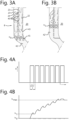
- Fig. 3a shows a diagrammatic sectional view of a bottom part of the milk filter at a first pulse
- Fig. 3b shows a diagrammatic sectional view of a bottom part of the milk filter at a second pulse.
- Fig. 3a shows a bottom part of the milk filter 8, comprising the outer wall 23, the filter plate 21 with holes 40 and a bottom wall 41 and the core 20, as well as the first volume part 24 and the second volume part 22.
- the bottom part contains cleaning liquid 42 up to a level h 0 .
- the incoming stream of cleaning liquid plus compressed air 43 in the first pulse is shown diagrammatically. Arrows indicate the directions of flow therein.
- the new, fresh cleaning liquid, together with the compressed air 43 enters from above, initially via the inner filter volume or second volume part 22.
- This fresh cleaning liquid also passes virtually immediately through the holes 40 to the outer filter volume or first volume part 24.
- the stream of the cleaning liquid comprising compressed air 23 hits the bottom wall 41 of the filter plate 21 as well as the previously collected amount of cleaning liquid 42, which is indicated by an opposite hatching and has reached a level h 0 .
- a great turbulence occurs, even with a local countercurrent, both in the fresh cleaning liquid 43 and in the upper layer of the previously collected cleaning liquid 42.
- Fig. 3b shows a diagrammatic sectional view of a bottom part of the milk filter at a second pulse.
- the first pulse for the sake of convenience here referred to as the first pulse
- a certain amount of cleaning liquid 42' has collected in the milk filter 8, up to a level h 1 .
- This cleaning liquid could be collected because, in net terms, less liquid was able to flow away than has entered.
- the three-way valve 30 or any other valve in the discharge of cleaning liquid, or the supply of cleaning liquid or a combination thereof is controlled in such a way by the control unit that the desired level in the milk filter is reached at the end of draining, between two pulses.
- the passage of a possible valve in the discharge, the flow rate of the cleaning liquid and the pulse time and draining time are available as variables, among others.
- Fig. 4a gives an example of a stream of cleaning liquid as a function of time.
- Fig. 4b gives an associated level h in the milk filter.
- t 0.5 s
- T 0.75 s
- the number of pulses is 7, but any desired number greater or equal to 2 is possible in principle.
- the pulses are all equal, although this is not obligatory and it would for example also be possible to increase the pulse duration t or to increase the flow rate during the pulse in order to raise the level in the milk filter at the end of the draining time or, if desired, lower it, at least take it to a desired level. Furthermore, it is not obligatory for the level h of the cleaning liquid in the milk filter to increase from pulse to pulse at the end of the draining time.
Landscapes
- Life Sciences & Earth Sciences (AREA)
- Animal Husbandry (AREA)
- Environmental Sciences (AREA)
- Dairy Products (AREA)
- Apparatus For Making Beverages (AREA)
Claims (12)
- Dispositif de traite (1) pour traire un animal laitier (100), et comportant- des moyens de traite (2),- une unité de commande (13) pour le dispositif de traite,- un lactoduc (5-1, 5-2, 5-3) pour transporter le lait depuis les moyens de traite vers une cuve à lait (7),- un filtre à lait (8) pour filtrer le lait passant à travers le lactoduc, et- un dispositif de nettoyage pour nettoyer le filtre à lait avec du liquide de nettoyage (42, 43),le filtre à lait comprenant :- un boîtier (23) qui renferme un volume (22, 24) de filtre et qui comprend une partie d'entrée de lait (15) avec une entrée de lait (18), une partie de sortie de lait (17) avec une sortie de lait (19), et une paroi circonférentielle extérieure (23) entre elles,- un composant (21) de filtre qui est placé dans le volume de filtre et comprend une partie de plaque circonférentielle comprenant une pluralité de trous (40) de filtre, et qui sépare le volume de filtre en un volume central intérieur (22) de filtre qui est relié à l'une parmi l'entrée de lait et la sortie de lait, et un volume extérieur (24) de filtre le renfermant, et relié à l'autre parmi l'entrée de lait et la sortie de lait,caractérisé en ce que le filtre à lait est configuré pour être rincé, en cours d'utilisation, dans une première direction avec le lait à filtrer, laquelle première direction s'étend depuis l'entrée de lait vers la sortie de lait,le dispositif de nettoyage étant configuré pour nettoyer le filtre à lait en faisant passer du liquide de nettoyage (42, 43) à travers le filtre à lait dans une direction à contre-courant opposée à la première direction en au moins deux impulsions consécutives, de telle manière que, à chaque impulsion :- durant une première phase d'impulsion, davantage de liquide de nettoyage est introduit qu'évacué, et- par la suite, durant une deuxième phase d'impulsion, au moins autant de liquide de nettoyage s'écoule du volume de filtre qu'il y est introduit, de telle manière qu'une quantité de liquide de nettoyage s'est accumulée dans le volume de filtre jusqu'à un niveau de liquide (h1) qui entoure au moins une partie de la pluralité de trous.
- Dispositif de traite selon la revendication 1, le niveau de liquide (h1) se situant dans une moitié supérieure de la pluralité de trous.
- Dispositif de traite selon l'une des revendications précédentes, le dispositif de nettoyage étant configuré pour modifier le niveau de liquide d'une impulsion à l'autre, en particulier pour l'augmenter d'une impulsion à l'autre.
- Dispositif de traite selon l'une des revendications précédentes, une fréquence des impulsions étant supérieure à 0,5 Hz.
- Dispositif de traite selon l'une des revendications précédentes, la deuxième phase d'impulsion étant inférieure à 1 seconde, avantageusement d'au plus 0,5 seconde.
- Dispositif de traite selon l'une des revendications précédentes, le nombre d'impulsions étant compris entre 2 et 20.
- Dispositif de traite selon l'une des revendications précédentes, comprenant un dispositif de pression qui est configuré pour fournir du liquide de nettoyage sous pression au filtre à lait, en particulier comprenant un accumulateur pour le fluide de nettoyage.
- Dispositif de traite selon l'une des revendications précédentes, comprenant une alimentation en air comprimé (26, 28) pour alimenter le liquide de nettoyage en air comprimé avant qu'il ne pénètre dans le volume de fluide.
- Dispositif de traite selon l'une des revendications précédentes, comprenant un dispositif de vanne d'entrée (25) pouvant être commandé par l'unité de commande pour commander une alimentation en liquide de nettoyage, et/ou un dispositif de vanne de sortie (30) pouvant être commandé par l'unité de commande pour commander une évacuation du liquide de nettoyage.
- Dispositif de traite selon l'une des revendications précédentes, le volume intérieur de filtre étant relié à la sortie de lait et, en particulier, ladite paroi extérieure étant transparente.
- Dispositif de traite selon l'une des revendications précédentes, le boîtier étant sensiblement cylindrique et ledit composant de filtre étant une plaque métallique qui est concentrique avec la paroi extérieure.
- Dispositif de traite selon l'une des revendications précédentes, comprenant un cœur (20) dans le volume intérieur de filtre qui est concentrique avec ladite paroi extérieure, avantageusement s'étendant le long de toute la pluralité de trous.
Applications Claiming Priority (2)
| Application Number | Priority Date | Filing Date | Title |
|---|---|---|---|
| NL2026404A NL2026404B1 (nl) | 2020-09-03 | 2020-09-03 | Melkinrichting |
| PCT/IB2021/058018 WO2022049515A1 (fr) | 2020-09-03 | 2021-09-02 | Dispositif de traite |
Publications (2)
| Publication Number | Publication Date |
|---|---|
| EP4208014A1 EP4208014A1 (fr) | 2023-07-12 |
| EP4208014B1 true EP4208014B1 (fr) | 2025-03-26 |
Family
ID=72709829
Family Applications (1)
| Application Number | Title | Priority Date | Filing Date |
|---|---|---|---|
| EP21798767.6A Active EP4208014B1 (fr) | 2020-09-03 | 2021-09-02 | Dispositif de traite |
Country Status (6)
| Country | Link |
|---|---|
| US (1) | US12201081B2 (fr) |
| EP (1) | EP4208014B1 (fr) |
| CN (1) | CN116209354B (fr) |
| CA (1) | CA3191307A1 (fr) |
| NL (1) | NL2026404B1 (fr) |
| WO (1) | WO2022049515A1 (fr) |
Families Citing this family (2)
| Publication number | Priority date | Publication date | Assignee | Title |
|---|---|---|---|---|
| NL2030195B1 (nl) | 2021-12-20 | 2023-06-28 | Lely Patent Nv | Melkinrichting |
| NL2036442B1 (nl) | 2023-12-06 | 2025-06-17 | Lely Patent Nv | Melksysteem met een melktransportleiding en een filterinrichting voor het filteren van melk in de melktransportleiding |
Family Cites Families (15)
| Publication number | Priority date | Publication date | Assignee | Title |
|---|---|---|---|---|
| US3139857A (en) * | 1963-01-08 | 1964-07-07 | Babson Bros Co | Milk filtering arrangement |
| US3829584A (en) * | 1972-08-21 | 1974-08-13 | Economics Lab | Continuous separating and standardizing of milk |
| US4061504A (en) * | 1976-05-21 | 1977-12-06 | Cornell Research Foundation, Inc. | Apparatus for cleaning automatic milking machines |
| DK232579A (da) * | 1978-06-06 | 1979-12-07 | Diversey Corp | Filter og filterelement til brug i filteret |
| NL8102764A (nl) * | 1981-06-09 | 1983-01-03 | Metaalgaasweverij Dinxperlo B | Melkfilter. |
| US4637879A (en) * | 1984-11-15 | 1987-01-20 | Hartley Philip J | Apparatus for use in filtering a liquid |
| NL9301985A (nl) * | 1993-11-17 | 1995-06-16 | Texas Industries Inc | Melkmachine. |
| US5896828A (en) * | 1997-05-22 | 1999-04-27 | Alfa Laval Agri Inc. | Method and apparatus for cleaning milking pipelines and milking equipment |
| NL1017047C2 (nl) * | 2001-01-08 | 2002-07-09 | Lely Entpr Ag | Inrichting en werkwijze voor het reinigen van een melkmachine en melkmachine. |
| US20100310711A1 (en) * | 2009-06-08 | 2010-12-09 | Kendell Lamar Chet | Milk filtration system |
| NL1037403C2 (nl) | 2009-10-15 | 2011-04-18 | Boetech Automatisering B V | Automatische zelfreinigende melkfilter. |
| GB2475249A (en) * | 2009-11-10 | 2011-05-18 | Delaval Holding Ab | Method and apparatus for cleaning a milking system |
| US9332726B2 (en) * | 2010-11-16 | 2016-05-10 | Delaval Holding Ab | Milking system, and a method for operating a milking system |
| SE535787C2 (sv) * | 2010-12-22 | 2012-12-18 | Ninni Petersson | Vattenrenare och metod för att rena vatten |
| NL2014186B1 (nl) * | 2015-01-26 | 2017-01-05 | Lely Patent Nv | Melkinrichting. |
-
2020
- 2020-09-03 NL NL2026404A patent/NL2026404B1/nl active
-
2021
- 2021-09-02 US US18/021,728 patent/US12201081B2/en active Active
- 2021-09-02 CA CA3191307A patent/CA3191307A1/fr active Pending
- 2021-09-02 WO PCT/IB2021/058018 patent/WO2022049515A1/fr not_active Ceased
- 2021-09-02 EP EP21798767.6A patent/EP4208014B1/fr active Active
- 2021-09-02 CN CN202180054080.7A patent/CN116209354B/zh active Active
Also Published As
| Publication number | Publication date |
|---|---|
| CN116209354B (zh) | 2025-03-14 |
| US20240008442A1 (en) | 2024-01-11 |
| WO2022049515A1 (fr) | 2022-03-10 |
| CN116209354A (zh) | 2023-06-02 |
| EP4208014A1 (fr) | 2023-07-12 |
| US12201081B2 (en) | 2025-01-21 |
| CA3191307A1 (fr) | 2022-03-10 |
| NL2026404B1 (nl) | 2022-05-04 |
Similar Documents
| Publication | Publication Date | Title |
|---|---|---|
| EP4208014B1 (fr) | Dispositif de traite | |
| AU730692C (en) | A method of cleaning a filter unit, and a filter unit for filtering gas | |
| US12520812B2 (en) | Milking device including tube-shaped filter component | |
| EP4376597B1 (fr) | Dispositif de traite pourvu d'un filtre à lait | |
| CN116056567B (zh) | 奶过滤器和设置有其的挤奶装置 | |
| JP4083192B2 (ja) | 飲料抽出装置及び抽出残渣の除去方法 | |
| JP6106871B1 (ja) | 混合システム、ミキシングタンク用の洗浄装置、及び、スラリーの製造方法 | |
| EP4451859B1 (fr) | Dispositif de traite, filtre à lait et cartouche de filtre | |
| JPH09276860A (ja) | 水位変動用スカム除去装置 | |
| JP7035307B2 (ja) | 洗浄装置 | |
| CN206838337U (zh) | 除垢装置及花洒 | |
| EP1317173A1 (fr) | Filtration du lait et regeneration du filtre | |
| CN109013601A (zh) | 清淤系统和清淤方法 | |
| JP2022188978A (ja) | ろ過装置、及びろ過装置の運転方法 | |
| GB1565184A (en) | Bean sprout washing and separating apparatus |
Legal Events
| Date | Code | Title | Description |
|---|---|---|---|
| STAA | Information on the status of an ep patent application or granted ep patent |
Free format text: STATUS: UNKNOWN |
|
| STAA | Information on the status of an ep patent application or granted ep patent |
Free format text: STATUS: THE INTERNATIONAL PUBLICATION HAS BEEN MADE |
|
| PUAI | Public reference made under article 153(3) epc to a published international application that has entered the european phase |
Free format text: ORIGINAL CODE: 0009012 |
|
| STAA | Information on the status of an ep patent application or granted ep patent |
Free format text: STATUS: REQUEST FOR EXAMINATION WAS MADE |
|
| 17P | Request for examination filed |
Effective date: 20230403 |
|
| AK | Designated contracting states |
Kind code of ref document: A1 Designated state(s): AL AT BE BG CH CY CZ DE DK EE ES FI FR GB GR HR HU IE IS IT LI LT LU LV MC MK MT NL NO PL PT RO RS SE SI SK SM TR |
|
| DAV | Request for validation of the european patent (deleted) | ||
| DAX | Request for extension of the european patent (deleted) | ||
| STAA | Information on the status of an ep patent application or granted ep patent |
Free format text: STATUS: EXAMINATION IS IN PROGRESS |
|
| 17Q | First examination report despatched |
Effective date: 20240314 |
|
| GRAP | Despatch of communication of intention to grant a patent |
Free format text: ORIGINAL CODE: EPIDOSNIGR1 |
|
| STAA | Information on the status of an ep patent application or granted ep patent |
Free format text: STATUS: GRANT OF PATENT IS INTENDED |
|
| INTG | Intention to grant announced |
Effective date: 20241113 |
|
| GRAS | Grant fee paid |
Free format text: ORIGINAL CODE: EPIDOSNIGR3 |
|
| GRAA | (expected) grant |
Free format text: ORIGINAL CODE: 0009210 |
|
| STAA | Information on the status of an ep patent application or granted ep patent |
Free format text: STATUS: THE PATENT HAS BEEN GRANTED |
|
| AK | Designated contracting states |
Kind code of ref document: B1 Designated state(s): AL AT BE BG CH CY CZ DE DK EE ES FI FR GB GR HR HU IE IS IT LI LT LU LV MC MK MT NL NO PL PT RO RS SE SI SK SM TR |
|
| P01 | Opt-out of the competence of the unified patent court (upc) registered |
Free format text: CASE NUMBER: APP_8469/2025 Effective date: 20250219 |
|
| REG | Reference to a national code |
Ref country code: GB Ref legal event code: FG4D |
|
| REG | Reference to a national code |
Ref country code: CH Ref legal event code: EP |
|
| REG | Reference to a national code |
Ref country code: NL Ref legal event code: FP |
|
| REG | Reference to a national code |
Ref country code: DE Ref legal event code: R096 Ref document number: 602021028220 Country of ref document: DE |
|
| REG | Reference to a national code |
Ref country code: IE Ref legal event code: FG4D |
|
| REG | Reference to a national code |
Ref country code: SE Ref legal event code: TRGR |
|
| PG25 | Lapsed in a contracting state [announced via postgrant information from national office to epo] |
Ref country code: RS Free format text: LAPSE BECAUSE OF FAILURE TO SUBMIT A TRANSLATION OF THE DESCRIPTION OR TO PAY THE FEE WITHIN THE PRESCRIBED TIME-LIMIT Effective date: 20250626 |
|
| PG25 | Lapsed in a contracting state [announced via postgrant information from national office to epo] |
Ref country code: FI Free format text: LAPSE BECAUSE OF FAILURE TO SUBMIT A TRANSLATION OF THE DESCRIPTION OR TO PAY THE FEE WITHIN THE PRESCRIBED TIME-LIMIT Effective date: 20250326 |
|
| REG | Reference to a national code |
Ref country code: LT Ref legal event code: MG9D |
|
| PG25 | Lapsed in a contracting state [announced via postgrant information from national office to epo] |
Ref country code: NO Free format text: LAPSE BECAUSE OF FAILURE TO SUBMIT A TRANSLATION OF THE DESCRIPTION OR TO PAY THE FEE WITHIN THE PRESCRIBED TIME-LIMIT Effective date: 20250626 |
|
| PG25 | Lapsed in a contracting state [announced via postgrant information from national office to epo] |
Ref country code: HR Free format text: LAPSE BECAUSE OF FAILURE TO SUBMIT A TRANSLATION OF THE DESCRIPTION OR TO PAY THE FEE WITHIN THE PRESCRIBED TIME-LIMIT Effective date: 20250326 |
|
| PG25 | Lapsed in a contracting state [announced via postgrant information from national office to epo] |
Ref country code: LV Free format text: LAPSE BECAUSE OF FAILURE TO SUBMIT A TRANSLATION OF THE DESCRIPTION OR TO PAY THE FEE WITHIN THE PRESCRIBED TIME-LIMIT Effective date: 20250326 |
|
| PG25 | Lapsed in a contracting state [announced via postgrant information from national office to epo] |
Ref country code: BG Free format text: LAPSE BECAUSE OF FAILURE TO SUBMIT A TRANSLATION OF THE DESCRIPTION OR TO PAY THE FEE WITHIN THE PRESCRIBED TIME-LIMIT Effective date: 20250326 Ref country code: GR Free format text: LAPSE BECAUSE OF FAILURE TO SUBMIT A TRANSLATION OF THE DESCRIPTION OR TO PAY THE FEE WITHIN THE PRESCRIBED TIME-LIMIT Effective date: 20250627 |
|
| REG | Reference to a national code |
Ref country code: AT Ref legal event code: MK05 Ref document number: 1778102 Country of ref document: AT Kind code of ref document: T Effective date: 20250326 |
|
| PG25 | Lapsed in a contracting state [announced via postgrant information from national office to epo] |
Ref country code: SM Free format text: LAPSE BECAUSE OF FAILURE TO SUBMIT A TRANSLATION OF THE DESCRIPTION OR TO PAY THE FEE WITHIN THE PRESCRIBED TIME-LIMIT Effective date: 20250326 |
|
| PG25 | Lapsed in a contracting state [announced via postgrant information from national office to epo] |
Ref country code: ES Free format text: LAPSE BECAUSE OF FAILURE TO SUBMIT A TRANSLATION OF THE DESCRIPTION OR TO PAY THE FEE WITHIN THE PRESCRIBED TIME-LIMIT Effective date: 20250326 Ref country code: PT Free format text: LAPSE BECAUSE OF FAILURE TO SUBMIT A TRANSLATION OF THE DESCRIPTION OR TO PAY THE FEE WITHIN THE PRESCRIBED TIME-LIMIT Effective date: 20250728 |
|
| PGFP | Annual fee paid to national office [announced via postgrant information from national office to epo] |
Ref country code: DE Payment date: 20250929 Year of fee payment: 5 |
|
| PG25 | Lapsed in a contracting state [announced via postgrant information from national office to epo] |
Ref country code: PL Free format text: LAPSE BECAUSE OF FAILURE TO SUBMIT A TRANSLATION OF THE DESCRIPTION OR TO PAY THE FEE WITHIN THE PRESCRIBED TIME-LIMIT Effective date: 20250326 Ref country code: IT Free format text: LAPSE BECAUSE OF FAILURE TO SUBMIT A TRANSLATION OF THE DESCRIPTION OR TO PAY THE FEE WITHIN THE PRESCRIBED TIME-LIMIT Effective date: 20250326 |
|
| PGFP | Annual fee paid to national office [announced via postgrant information from national office to epo] |
Ref country code: NL Payment date: 20250926 Year of fee payment: 5 |
|
| PGFP | Annual fee paid to national office [announced via postgrant information from national office to epo] |
Ref country code: GB Payment date: 20250929 Year of fee payment: 5 |
|
| PG25 | Lapsed in a contracting state [announced via postgrant information from national office to epo] |
Ref country code: AT Free format text: LAPSE BECAUSE OF FAILURE TO SUBMIT A TRANSLATION OF THE DESCRIPTION OR TO PAY THE FEE WITHIN THE PRESCRIBED TIME-LIMIT Effective date: 20250326 |
|
| PGFP | Annual fee paid to national office [announced via postgrant information from national office to epo] |
Ref country code: FR Payment date: 20250925 Year of fee payment: 5 |
|
| PGFP | Annual fee paid to national office [announced via postgrant information from national office to epo] |
Ref country code: SE Payment date: 20250927 Year of fee payment: 5 |
|
| PG25 | Lapsed in a contracting state [announced via postgrant information from national office to epo] |
Ref country code: EE Free format text: LAPSE BECAUSE OF FAILURE TO SUBMIT A TRANSLATION OF THE DESCRIPTION OR TO PAY THE FEE WITHIN THE PRESCRIBED TIME-LIMIT Effective date: 20250326 |
|
| PG25 | Lapsed in a contracting state [announced via postgrant information from national office to epo] |
Ref country code: RO Free format text: LAPSE BECAUSE OF FAILURE TO SUBMIT A TRANSLATION OF THE DESCRIPTION OR TO PAY THE FEE WITHIN THE PRESCRIBED TIME-LIMIT Effective date: 20250326 |
|
| PG25 | Lapsed in a contracting state [announced via postgrant information from national office to epo] |
Ref country code: SK Free format text: LAPSE BECAUSE OF FAILURE TO SUBMIT A TRANSLATION OF THE DESCRIPTION OR TO PAY THE FEE WITHIN THE PRESCRIBED TIME-LIMIT Effective date: 20250326 |
|
| PG25 | Lapsed in a contracting state [announced via postgrant information from national office to epo] |
Ref country code: IS Free format text: LAPSE BECAUSE OF FAILURE TO SUBMIT A TRANSLATION OF THE DESCRIPTION OR TO PAY THE FEE WITHIN THE PRESCRIBED TIME-LIMIT Effective date: 20250726 |
|
| REG | Reference to a national code |
Ref country code: DE Ref legal event code: R097 Ref document number: 602021028220 Country of ref document: DE |
|
| PG25 | Lapsed in a contracting state [announced via postgrant information from national office to epo] |
Ref country code: DK Free format text: LAPSE BECAUSE OF FAILURE TO SUBMIT A TRANSLATION OF THE DESCRIPTION OR TO PAY THE FEE WITHIN THE PRESCRIBED TIME-LIMIT Effective date: 20250326 |
|
| PG25 | Lapsed in a contracting state [announced via postgrant information from national office to epo] |
Ref country code: CZ Free format text: LAPSE BECAUSE OF FAILURE TO SUBMIT A TRANSLATION OF THE DESCRIPTION OR TO PAY THE FEE WITHIN THE PRESCRIBED TIME-LIMIT Effective date: 20250326 |
|
| PLBE | No opposition filed within time limit |
Free format text: ORIGINAL CODE: 0009261 |
|
| STAA | Information on the status of an ep patent application or granted ep patent |
Free format text: STATUS: NO OPPOSITION FILED WITHIN TIME LIMIT |
|
| REG | Reference to a national code |
Ref country code: CH Ref legal event code: L10 Free format text: ST27 STATUS EVENT CODE: U-0-0-L10-L00 (AS PROVIDED BY THE NATIONAL OFFICE) Effective date: 20260211 |
|
| 26N | No opposition filed |
Effective date: 20260105 |