EP4208054B1 - Cartomiseur pour un dispositif de génération d'aérosol avec prévention des fuites - Google Patents
Cartomiseur pour un dispositif de génération d'aérosol avec prévention des fuites Download PDFInfo
- Publication number
- EP4208054B1 EP4208054B1 EP21773022.5A EP21773022A EP4208054B1 EP 4208054 B1 EP4208054 B1 EP 4208054B1 EP 21773022 A EP21773022 A EP 21773022A EP 4208054 B1 EP4208054 B1 EP 4208054B1
- Authority
- EP
- European Patent Office
- Prior art keywords
- cartomizer
- leakage collecting
- collecting chamber
- chamber
- air
- Prior art date
- Legal status (The legal status is an assumption and is not a legal conclusion. Google has not performed a legal analysis and makes no representation as to the accuracy of the status listed.)
- Active
Links
Images


Classifications
-
- A—HUMAN NECESSITIES
- A24—TOBACCO; CIGARS; CIGARETTES; SIMULATED SMOKING DEVICES; SMOKERS' REQUISITES
- A24F—SMOKERS' REQUISITES; MATCH BOXES; SIMULATED SMOKING DEVICES
- A24F40/00—Electrically operated smoking devices; Component parts thereof; Manufacture thereof; Maintenance or testing thereof; Charging means specially adapted therefor
- A24F40/40—Constructional details, e.g. connection of cartridges and battery parts
-
- A—HUMAN NECESSITIES
- A24—TOBACCO; CIGARS; CIGARETTES; SIMULATED SMOKING DEVICES; SMOKERS' REQUISITES
- A24F—SMOKERS' REQUISITES; MATCH BOXES; SIMULATED SMOKING DEVICES
- A24F40/00—Electrically operated smoking devices; Component parts thereof; Manufacture thereof; Maintenance or testing thereof; Charging means specially adapted therefor
- A24F40/40—Constructional details, e.g. connection of cartridges and battery parts
- A24F40/42—Cartridges or containers for inhalable precursors
-
- A—HUMAN NECESSITIES
- A24—TOBACCO; CIGARS; CIGARETTES; SIMULATED SMOKING DEVICES; SMOKERS' REQUISITES
- A24F—SMOKERS' REQUISITES; MATCH BOXES; SIMULATED SMOKING DEVICES
- A24F40/00—Electrically operated smoking devices; Component parts thereof; Manufacture thereof; Maintenance or testing thereof; Charging means specially adapted therefor
- A24F40/10—Devices using liquid inhalable precursors
-
- A—HUMAN NECESSITIES
- A24—TOBACCO; CIGARS; CIGARETTES; SIMULATED SMOKING DEVICES; SMOKERS' REQUISITES
- A24F—SMOKERS' REQUISITES; MATCH BOXES; SIMULATED SMOKING DEVICES
- A24F40/00—Electrically operated smoking devices; Component parts thereof; Manufacture thereof; Maintenance or testing thereof; Charging means specially adapted therefor
- A24F40/40—Constructional details, e.g. connection of cartridges and battery parts
- A24F40/44—Wicks
-
- A—HUMAN NECESSITIES
- A24—TOBACCO; CIGARS; CIGARETTES; SIMULATED SMOKING DEVICES; SMOKERS' REQUISITES
- A24F—SMOKERS' REQUISITES; MATCH BOXES; SIMULATED SMOKING DEVICES
- A24F40/00—Electrically operated smoking devices; Component parts thereof; Manufacture thereof; Maintenance or testing thereof; Charging means specially adapted therefor
- A24F40/40—Constructional details, e.g. connection of cartridges and battery parts
- A24F40/48—Fluid transfer means, e.g. pumps
- A24F40/485—Valves; Apertures
-
- A—HUMAN NECESSITIES
- A24—TOBACCO; CIGARS; CIGARETTES; SIMULATED SMOKING DEVICES; SMOKERS' REQUISITES
- A24F—SMOKERS' REQUISITES; MATCH BOXES; SIMULATED SMOKING DEVICES
- A24F40/00—Electrically operated smoking devices; Component parts thereof; Manufacture thereof; Maintenance or testing thereof; Charging means specially adapted therefor
- A24F40/85—Maintenance, e.g. cleaning
Definitions
- the present invention relates to a cartomizer for an aerosol generating device, in particular an electronic cigarette or vaporizer, with a leakage prevention system, in particular a double leakage chamber arrangement.
- Aerosol generating devices such as electronic cigarettes or "e-cigarettes” as they are also known, have gained in popularity over the past ten years as an alternative to traditional smoking articles, like cigarettes, cigars, and cigarillos. Developments in the design and configuration of such aerosol generating devices or vaporizer devices are ongoing to improve their performance and their reliability, as well as their ease of production and their production costs.
- Conventional aerosol generating devices usually include a heater powered by an electrical power source and a liquid reservoir containing flavoured liquid (vaporizable material) that can be volatized using the heater and transferred to a user of the aerosol generating device in an airflow, which is preferably guided through a mouthpiece of the device.
- the heating element is often provided within the capsule, thereby forming a so called “cartomizer".
- the heating element is provided with the cartomizer, it is each time the cartomizer (capsule) is replaced, hence, there is no reduction in performance over time.
- a liquid transport element in particular a wick
- a coil that is wound around the wick
- measures should be put in place that contain leaked vaporizable material within the capsule, should leakage occur. Therefore, it is desirable to provide a cartomizer with means that can prevent leaking vaporizable material to affect either the device or consumer.
- US 9,737,093 B2 is related to an electronic cigarette comprising from a first, vaping end and a second end distal from the user's mouth, a cartridge, a vaporizer and a battery. It is further disclosed to provide a circular chamber that has direct access to the vaporizing chamber in order to collect leaking vaporizable material. A similar device is shown in US 2019/0335813 A1 .
- a cartomizer for an aerosol generating device in particular an electronic cigarette or vaporizer, capable of preventing leakage of vaporizable material or liquid from the heater or the liquid transport element (wick) to the outside of the cartomizer, in particular via an air inlet of the cartomizer, thereby ensuring that leaked vaporizable material or liquid affects either the device or consumer.
- a cartomizer for an aerosol generating device in particular an electronic cigarette or vaporizer
- the cartomizer including: a container for holding at least one reservoir configured to contain a vaporizable material, a vaporizing chamber fluidly connected to a mouth end by a vapor passage, a liquid transport element, in particular a porous capillary member, extending from inside the at least one reservoir to the inside of the vaporizing chamber in order to convey or wick or otherwise transport the vaporizable material from the at least one reservoir to the inside of the vaporizing chamber and an air inlet arranged to supply the vaporizing chamber with air in use, wherein a leakage collecting chamber is arranged, in particular in an airflow direction from the air inlet to the vaporizing chamber, between the vaporizing chamber and the air inlet to collect vaporizable material (leaking) from the vaporizing chamber, and the leakage collecting chamber includes at least one liquid stopping or barrier wall, in particular a first liquid stopping
- a cartomizer for an aerosol generating device capable of reducing the likelihood that vaporizable material or liquid, leaking from the liquid transport element or a heater of the cartomizer reaches the outside of the cartomizer via the air inlet. Thereby, ensuring that leaked vaporizable material or liquid is prevented from affecting the device or a user of the device.
- the air inlet may comprise or may be formed by an air conduit or chimney that is arranged at the bottom of the container and upstream the through-hole of the air inlet, wherein the air conduit or chimney, in particular a sidewall thereof, forms a second liquid stopping or barrier wall that is arranged between the first liquid stopping or barrier wall and the at least one through-hole.
- the air conduit or chimney may protrude inside the leakage collecting chamber.
- the cartomizer may further include a center leakage collecting chamber that is provided between the air inlet and the leakage collecting chamber, in particular in an airflow direction from the air inlet to the vaporizing chamber, wherein the center leakage collecting chamber is preferably defined or formed by the air conduit or chimney and the first liquid stopping or barrier wall.
- the center leakage collecting chamber and the leakage collecting chamber or the leakage collecting chambers are at least partially separated from each other by the first liquid stopping or barrier wall including at least one connecting hole or groove (fluidly) connecting the center leakage collecting chamber with the leakage collecting chamber or chambers, wherein the connecting hole or groove is preferably arranged with a predetermined axial distance to the bottom of the container.
- the predetermined axial distance from the at least one connecting hole or groove to the bottom of the container is smaller than an axial distance of the at least one through-hole to the bottom of the container.
- the leakage collecting chamber may further include at least one air outlet arranged at an axial distance relative to the through-hole of the air inlet, wherein the at least one air outlet of the leakage collecting chamber is preferably arranged axially, in particular in an axial direction of the cartomizer, closer to the bottom of the container than the through-hole of the air inlet.
- the "axial direction of the cartomizer” defines in the present application in general a longitudinal direction of the cartomizer.
- the "axial direction of the cartomizer” also refers to a direction in which the air flows in general through the cartomizer, namely from the air inlet of the cartomizer to the mouth end of the cartomizer, which is configured to come into contact with the lips of a user during use of the aerosol generating device.
- the air outlet of the leakage collecting chamber may be transversally distant from the air inlet.
- the air outlet might be arranged with a predetermined distance to the air inlet when seen in a plane perpendicular to the axial direction of the cartomizer. Therefore, in use, liquid entering the leakage collecting chamber through the air outlet has no straight path to the air inlet and becomes collected in the collecting chamber instead.
- the air outlet of the leakage collecting chamber may protrude by a conduit inside the leakage collecting chamber and/or inside the vaporizing chamber.
- the leakage collecting chamber may include two air outlets communicating with the vaporizing chamber and arranged on each side of the air inlet.
- the cartomizer may be provided with two leakage collecting chambers, which are each arranged on each side of the air inlet and provided with a separate air outlet communicating with the vaporizing chamber.
- the air outlets may be aligned in a plane of extension of the liquid transport element, which preferably is perpendicular to the axial direction of the device.
- the leakage collecting chamber is arranged between a first seal arranged or configured for holding the liquid transport element and a wall of the container, preferably a bottom holder of the container arranged for holding electrical connectors.
- the liquid transport element is held by the first seal and a second seal. Both seals may be made of silicone rubber.
- the second seal may at least partially, in particular completely, separate the at least one reservoir from the vaporizing chamber. Same applies in case the cartomizer is provided with two or more reservoirs.
- the at least one air outlet may be formed inside the first seal.
- the leakage collection chamber is demarcated by the first seal and the bottom holder of the container.
- the leakage collecting chamber may have a larger transversal cross section than the vaporizing chamber.
- the cross-sectional area of the leakage collecting chamber or collecting chambers is larger than the cross-sectional area of the vaporizing chamber.
- the first seal may include air channels that fluidly connect the center leakage collecting chamber with the leakage collecting chamber or the leakage collecting chambers.
- the container, shell or outside casing of the cartomizer may be formed of a rigid material, in particular a rigid thermoplastic material, glass or metal.
- Aerosol generating devices use electrical energy to heat a material (preferably without combusting the material to any significant degree and/or without significant chemical alteration of the material) to form an inhalable substance or vapor; and components of such device have the form of articles that most preferably are sufficiently compact to be considered hand-held devices.
- use of components of preferred aerosol generating devices does not result in the production of smoke in the sense that aerosol results principally from by-products of combustion or pyrolysis of tobacco, but rather, use of those devices preferably results in the production of vapors resulting from volatilization or vaporization of certain components incorporated therein.
- components of aerosol generating devices may be characterized as electronic cigarettes, and those electronic cigarettes preferably incorporate aerosolisable liquid (e.g. propylene glycol, polyhydric alcohol), tobacco and/or tobacco materials derived at least partially from tobacco, and hence deliver tobacco derived components in aerosol or vapor form to a user.
- aerosol generating devices within the meaning of the present invention may transport the volatilized particles in an airflow through the aerosol generating device, in particular through the cartomizer, to a user of the device, the user of the device being able to activate or deactivate the generation of aerosol and to control the duration, velocity and volume of the airflow by means of puffing or inhaling action.
- Figure 1 illustrates a known aerosol generating or delivery device 200 including a control body 202 and a tank 204.
- the control body 202 can be formed of a control body shell 206 that can include a control component 208 (e.g., a printed circuit board (PCB), an integrated circuit, a memory component, a microprocessor, individually or as part of a micro-controller, and the like), a flow sensor 210, a battery 212, and one or more light-emitting diodes (LEDs) 214, and such components can be variably aligned.
- a control component 208 e.g., a printed circuit board (PCB), an integrated circuit, a memory component, a microprocessor, individually or as part of a micro-controller, and the like
- a flow sensor 210 e.g., a battery 212
- LEDs light-emitting diodes
- the tank 204 can be formed of a tank shell 216 enclosing a reservoir 218 that is in fluid communication with a liquid transport element 220 adapted to wick or otherwise transport an aerosol precursor composition stored in the reservoir housing to a heater 222 (sometimes referred to as a heating element).
- a valve may be positioned between the reservoir and heater and configured to control an amount of aerosol precursor composition passed or delivered from the reservoir to the heater.
- the known device is provided with a mouthpiece 224 having an opening defined therein and which may be coupled to the tank shell 216 to allow for egress of formed aerosol from the tank 204.
- the shown device 200 in particular the control body 202 and the tank 204, include a coupler 230 having a cavity 232 therein.
- a base 228 of the tank is adapted to engage the coupler and includes a projection 234 to fit within the cavity.
- Aerosol generating devices of the present invention generally include a number of components provided within an outer body or shell, which may be referred to as an outside casing or housing.
- the overall design of the outside casing can vary, and the format or configuration of the outside casing that can define the overall size and shape of the aerosol generating device can vary.
- an elongated body resembling the shape of a cigarette or cigar can be formed from a single, unitary housing, or the elongated housing can be formed of two or more separable bodies.
- an aerosol generating device can include an elongated shell or body (outside casing) that can be substantially tubular in shape and, as such, resemble the shape of conventional cigarettes or cigars.
- all of the components of the aerosol generating device are contained within a single housing.
- an aerosol delivery device can comprise two or more housings that are joined and are separable.
- Aerosol generating devices of the present invention can be formed of an outside casing or shell that is not substantially tubular in shape but may be formed to substantially greater transversal dimensions.
- the outside casing or shell can be configured to include a mouthpiece and/or may be configured to receive a separate shell (e.g. a cartridge, a tank) that can include consumable elements, such as a liquid aerosol former, and can include a vaporizer.
- Figure 2 shows a schematic sectional view of the interior of a cartomizer 1 for an aerosol generating device 100 according to a first embodiment of the present invention.
- the cartomizer 1 is generally a container 10 or cartridge that can be at least partially inserted into a receiving cavity of an aerosol generating device and that provides the functionalities of generating an aerosol or vapor from a vaporizable material or liquid stored therein.
- a cartomizer can be a pre-manufactured and pre-filled cartridge that comprises at least one reservoir 11 for containing the vaporizable material or liquid from which the aerosol or vapor can be generated.
- the cartomizer 1 may further comprise a heater which is arranged to heat at least a fraction of the vaporizable material or liquid so as to vaporize an amount of it for, in turn, generating the aerosol or vapor.
- the heater may comprise any one and combination of a wire, a resistive element, a coil, and a susceptor being heatable by induction.
- the cartomizer 1 further comprises an air conduct and/or a mouthpiece (mouth end) 13 so as to allow a user to inhale the generated aerosol, preferably as a mixture with air from the environment.
- the heater is formed by a wire that is wound around a liquid transport element 15, in particular a capillary-type wick, such as bundle of cotton filaments, and located within a vaporizing chamber 12.
- the vaporizing chamber 12 is fluidly connected to the mouth end 13, in particular an opening provided in the mouth end 13, via a vapor passage 14.
- vapor generated by the heater can be provided via the vapor passage 14 and the opening in the mouth end 13 to a user.
- the cartomizer 1 is only provided with one reservoir 11 which surrounds the vapor passage 14, the heater and the liquid transport element 15.
- Both ends of the wick 15 reach into the reservoir 11, in particular into the vaporizable material stored inside the reservoir 11, on opposing sides and thereby convey, wick or otherwise transport the vaporizable material from the reservoir 11 to the heater which is positioned inside the vaporizing chamber 12.
- the cartomizer 1 is provided with an air inlet 16 which is arranged on the bottom, in particular in a bottom holder 17, of the container 10.
- the air inlet 16 is configured to supply the vaporizing chamber 12 with ambient air, which is sucked into the vaporizing chamber 12 during use of the aerosol generating device 100.
- Figure 2 also shows that the cartomizer 1 is additionally provided with a leakage collecting chamber 20 that is arranged in an airflow direction of the ambient air sucked into the cartomizer, namely from the air inlet 16 towards the vaporizing chamber, between the vaporizing chamber 12 and the air inlet 16 to collect vaporizable material leaking from the vaporizing chamber 12.
- a leakage collecting chamber 20 that is arranged in an airflow direction of the ambient air sucked into the cartomizer, namely from the air inlet 16 towards the vaporizing chamber, between the vaporizing chamber 12 and the air inlet 16 to collect vaporizable material leaking from the vaporizing chamber 12.
- the air path of the ambient air sucked into the cartomizer 1 through the air inlet 16 is the only unsealed connection between the environment and the vaporizing chamber 12, besides the vapor passage 14, the air path is the main source of possible leakage.
- FIG. 3 which is a schematic sectional view of a detail of the device 1 shown in Fig. 2 , by the arrows, vaporizable material or liquid leaking from the wick 15 drops onto a first sealing 30 that is configured to hold or fix the wick 15 within the vaporizing chamber 12, in particular together with a second sealing 31, and to form a part, in particular a bottom portion, of the vaporizing chamber 12. Thereby, the leaked vaporizable material or liquid is collected at the bottom of the vaporizing chamber 12.
- the first sealing 30 is provided with two air outlets 21 that are formed by two channels or through-holes that go through the first sealing 30, in particular in a direction parallel to the axial direction of the cartomizer 1.
- the two air outlets 21 are arranged at an axial distance relative to a through-hole 16a of the air inlet 16. Accordingly, the leaked vaporizable material or liquid collected at the bottom of the vaporizing chamber 12 flows through one of the air outlets 21 to the leakage collecting chamber 20 or one of the leakage collecting chambers 20.
- the air inlet 16 is provided with two through-holes 16a, which are aligned in a direction perpendicular to the axial direction of the cartomizer 1, which extends in Figure 4 in view direction, in other words, in a direction into the paper.
- Figures 3 and 4 also show that the two air outlets 21 are arranged on each side of the air inlet 16, in particular an air conduit or chimney 19 that forms the air inlet 16 and is provided at the bottom of the container 10. Moreover, the two air outlets 21 are aligned in a vertical plane (in Figs. 3 and 4 ) of extension of the liquid transport element 15.
- the leaked vaporizable material flows through the two air outlets 21 and reaches the leakage collecting chambers 20, which are also provided on each side of the air conduit or chimney 19 of the air inlet 16.
- the second sealing 31 separates the reservoir 11 from the vaporizing chamber 12, ensuring that the vaporizable material only reaches the heater via the wick 15.
- Figure 4 shows a vertical and a horizontal schematic sectional view of the cartomizer 1 shown in Fig. 2 , illustrating the air flow through the cartomizer 1.
- the ambient air entering the cartomizer 1 through the two through-holes 16a reaches a center leakage collecting chamber 22 that is provided in the bottom holder 17 of the container 10.
- the center leakage collecting chamber 22 is arranged between the air inlet 16 and the (main) leakage collecting chamber(s) 20. Meaning, the center leakage collecting chamber 22 is arranged between a side wall of the chimney 19 and a transversal wall of the first seal 30, forcing air to travel to the sides (as indicated by arrows in Fig. 4 ).
- the air entering the center leakage collecting chamber 22 flows through four air channels 30a which are provided in the first seal 30 thereby reaching the (main) leakage collecting chamber(s) 20.
- the four air channels 3a are arranged in a double-T form.
- Figure 5 shows a schematic spatial view of the bottom part of the device shown in Fig. 2 , in particular of the bottom holder 17 of the container 10. It should also be noted that the conduit or chimney 19 of the air inlet 16 forms part of the bottom holder 17. Moreover, as Figure 5 illustrates, the center leakage collecting chamber 22 and the two (main) leakage collecting chambers 20, which are arranged on each side of the center leakage collecting chamber 22, are separated from each other by at least one liquid stopping or barrier wall (here a first liquid stopping or barrier wall 23) including four connecting holes 25 (in this embodiment formed by cuts or grooves formed in the partition wall) that fluidly connect the center leakage collecting chamber 22 with the leakage collecting chambers 20.
- a liquid stopping or barrier wall here a first liquid stopping or barrier wall 23
- four connecting holes 25 in this embodiment formed by cuts or grooves formed in the partition wall
- the connecting holes are provided with a predetermined distance to the bottom of the container 10, leaked vaporizable material that is collected inside the (main) leakage collecting chambers 20 is prevented from entering the center leakage collecting chamber 22, even in extreme cartomizer orientations.
- the two air outlets 21, in particular bottom or upstream openings of them are provided closer to the bottom of the container 10 than the through-holes 16a of the air inlet 16, thereby ensuring that leaked vaporizable material collected inside the (main) leakage collecting chambers 20 does not close the air path, in particular the air path connecting the through-holes 16a of the air inlet 16 with the air outlets 21 via the leakage collecting chambers 20.
- the air conduit or chimney 19 in particular a side wall thereof, forms a second liquid stopping or barrier wall 24 that is arranged between the first liquid stopping or barrier wall 23 and the two through-holes 16a of the air inlet 16.
- the second liquid stopping or barrier wall forms a further overflow that ensures that no leaked vaporizing material reaches the air inlet 16.
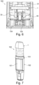
- Figure 6 shows a schematic sectional view of a detail of the cartomizer 1 shown in Fig. 2 when inserted into an aerosol generating device 100.
- the aerosol generating device 100 is provided with electrical contacts 105 such as "pogo pins" that are configured to contact the electrical connectors 18 of the cartomizer in order to provide the heater of the cartomizer 1 with electrical power.
- the electrical connectors 18 also contact magnets 104 which are provided within an inner frame 102 of the aerosol generating device 100.
- the cartomizer 1 is further provided with lead wires 40 that electrically connect the wire with the electrical connectors 18.
- FIG. 7 shows a schematic spatial view of a whole aerosol generating device 100 including the cartomizer according to the present invention, where only the outside casing of the aerosol generating device is not shown for illustrating purposes.
- the shown aerosol generating device 100 includes a mouthpiece which is part of the cartomizer 1 for guiding the generated vapor to a user, the cartomizer 1, a battery 101, a sealing arrangement 103 and an inner frame 102 for holding the battery 101 inside the device 100.
- the aerosol generating device 100 has an elongated shape, in which a receiving cavity for the cartomizer 1, a power supply device, in particular the battery 101, and a main electronic circuit board are arranged in this order from a first, proximal end (mouth end) to a second, distal end. Consequently, the power supply device, in particular battery 101, is located at approximately the center of the device 100, so that it is particularly well balanced.
Landscapes
- Catching Or Destruction (AREA)
- Disinfection, Sterilisation Or Deodorisation Of Air (AREA)
- Packaging Of Annular Or Rod-Shaped Articles, Wearing Apparel, Cassettes, Or The Like (AREA)
Claims (15)
- Cartomiseur (1) pour un dispositif (100) de génération d'aérosol, en particulier une cigarette électronique ou un vaporisateur, le cartomiseur comprenant :un récipient (10) pour renfermer au moins un réservoir (11) configuré pour contenir un matériau vaporisable ;une chambre de vaporisation (12) reliée de manière fluidique à une extrémité proximale (13) au moyen d'un passage (14) de vapeur ;un élément (15) de transport de liquide, en particulier un élément capillaire poreux, s'étendant de l'intérieur de l'au moins un réservoir (11) à l'intérieur de la chambre de vaporisation (12) afin de transporter le matériau vaporisable de l'au moins un réservoir (11) à l'intérieur de la chambre de vaporisation (12) ;une entrée d'air (16) agencée pour alimenter en air la chambre de vaporisation (12) lors de l'utilisation ;dans lequel une chambre de collecte de fuite (20) est agencée entre la chambre de vaporisation (12) et l'entrée d'air (16) pour collecter le matériau vaporisable provenant de la chambre de vaporisation (12), et la chambre de collecte de fuite (20) comprend au moins une paroi (23, 24) d'arrêt de liquide ou étanche aux liquides, en particulier une première paroi (23) d'arrêt de liquide ou étanche aux liquides, agencée entre la chambre de collecte de fuite (20) et l'entrée d'air (16), en particulier au moins un trou traversant (16a) de l'entrée d'air (16), formant un trop-plein, etle cartomiseur (1) comprend en outre une chambre de collecte de fuite centrale (22) qui est disposée entre l'entrée d'air (16) et la chambre de collecte de fuite (20).
- Cartomiseur (1) selon la revendication 1, dans lequel l'entrée d'air (16) comprend un conduit d'air ou une cheminée (19) au fond du récipient (10) et en amont de l'au moins un trou traversant (16a), formant une deuxième paroi (24) d'arrêt de liquide ou étanche aux liquides agencée entre la première paroi (23) d'arrêt de liquide ou étanche aux liquides et l'au moins un trou traversant (16a).
- Cartomiseur (1) selon la revendication 2, dans lequel le conduit d'air ou la cheminée fait saillie à l'intérieur de la chambre de collecte de fuite (20).
- Cartomiseur (1) selon la revendication 2 ou la revendication 3, dans lequel la chambre de collecte de fuite centrale (22) est définie ou formée par le conduit d'air ou la cheminée (19) et la première paroi (23) d'arrêt de liquide ou étanche aux liquides.
- Cartomiseur (1) selon la revendication 4, dans lequel la chambre de collecte de fuite centrale (22) et la ou les chambres de collecte de fuite (20) sont au moins partiellement séparés les unes les autres par la première paroi (23) d'arrêt de liquide ou étanche aux liquides incluant au moins un trou ou une rainure de liaison (25) reliant (de manière fluidique) la chambre de collecte de fuite centrale (22) à la ou aux chambres de collecte de fuite (20), dans lequel le trou ou la rainure de liaison (25) est de préférence agencé(e) avec une distance axiale prédéterminée par rapport au fond du récipient (10).
- Cartomiseur (1) selon la revendication 5, dans lequel la distance axiale prédéterminée de l'au moins un trou ou une rainure de liaison (25) au fond du récipient est inférieure à une distance axiale de l'au moins un trou traversant (16a) au fond du récipient (10).
- Cartomiseur selon l'une quelconque des revendications précédentes, dans lequel la chambre de collecte de fuite (20) comprend en outre au moins une sortie d'air (21) agencée à une distance axiale par rapport au trou traversant (16a) de l'entrée d'air (16), dans lequel l'au moins une sortie d'air (21) de la chambre de collecte de fuite (20) est de préférence agencée axialement plus près du fond du récipient (10) que le trou traversant (16a) de l'entrée d'air (16).
- Cartomiseur (1) selon la revendication 7, dans lequel la sortie d'air (21) de la chambre de collecte de fuite (20) est éloignée transversalement de l'entrée d'air (16).
- Cartomiseur (1) selon la revendication 7 ou la revendication 8, dans lequel la sortie d'air (21) de la chambre de collecte de fuite (20) fait saillie par un conduit à l'intérieur de la chambre de collecte de fuite (20) et/ou à l'intérieur de la chambre de vaporisation (12)
- Cartomiseur (1) selon l'une quelconque des revendications précédentes, dans lequel la chambre de collecte de fuite (20) comprend deux sorties d'air (21) communiquant avec la chambre de vaporisation (12) et agencées de chaque côté de l'entrée d'air (16), dans lequel les sorties d'air (21) sont de préférence alignées dans un plan d'extension de l'élément (15) de transport de liquide.
- Cartomiseur (1) selon l'une quelconque des revendications précédentes, dans lequel la chambre de collecte de fuite (20) est agencée entre un premier joint (30) agencé pour maintenir l'élément (15) de transport de liquide et un support inférieur (17) du récipient (10) agencé pour maintenir des connecteurs électriques (18).
- Cartomiseur (1) selon la revendication 11, dans lequel l'élément (15) de transport de liquide est maintenu par le premier joint (30) et un deuxième joint (31), dans lequel le deuxième joint (31) sépare, de préférence au moins partiellement, en particulier complètement, l'au moins un réservoir (11) de la chambre de vaporisation (12).
- Cartomiseur (1) selon la revendication 12, dans lequel l'au moins une sortie d'air (21) est formée à l'intérieur du premier joint (30).
- Cartomiseur (1) selon l'une quelconque des revendications précédentes, dans lequel la chambre de collecte de fuite (20) a une section transversale plus grande que la chambre de vaporisation (12).
- Cartomiseur (1) selon l'une quelconque des revendications 9 à 11 et la revendication 12, dans lequel le premier joint (30) inclut des canaux d'air (30a) qui relient de manière fluidique la chambre de collecte de fuite centrale (22) à la chambre de collecte de fuite (20) ou aux chambres de collecte de fuite (20).
Applications Claiming Priority (2)
| Application Number | Priority Date | Filing Date | Title |
|---|---|---|---|
| EP20194597 | 2020-09-04 | ||
| PCT/EP2021/074124 WO2022049120A1 (fr) | 2020-09-04 | 2021-09-01 | Cartomiseur pour un dispositif de génération d'aérosol avec prévention de fuite |
Publications (3)
| Publication Number | Publication Date |
|---|---|
| EP4208054A1 EP4208054A1 (fr) | 2023-07-12 |
| EP4208054B1 true EP4208054B1 (fr) | 2024-11-06 |
| EP4208054C0 EP4208054C0 (fr) | 2024-11-06 |
Family
ID=72380992
Family Applications (1)
| Application Number | Title | Priority Date | Filing Date |
|---|---|---|---|
| EP21773022.5A Active EP4208054B1 (fr) | 2020-09-04 | 2021-09-01 | Cartomiseur pour un dispositif de génération d'aérosol avec prévention des fuites |
Country Status (4)
| Country | Link |
|---|---|
| US (1) | US20230309614A1 (fr) |
| EP (1) | EP4208054B1 (fr) |
| CA (1) | CA3188844A1 (fr) |
| WO (1) | WO2022049120A1 (fr) |
Families Citing this family (2)
| Publication number | Priority date | Publication date | Assignee | Title |
|---|---|---|---|---|
| WO2025110240A1 (fr) * | 2023-11-23 | 2025-05-30 | 日本たばこ産業株式会社 | Cartouche, dispositif de génération d'aérosol et inhalateur de type sans combustion |
| CN222109302U (zh) * | 2024-04-01 | 2024-12-06 | 爱奇迹创造有限公司 | 雾化器及电子雾化装置 |
Citations (12)
| Publication number | Priority date | Publication date | Assignee | Title |
|---|---|---|---|---|
| US9737093B2 (en) | 2012-04-26 | 2017-08-22 | Fontem Holdings 1 B.V. | Electronic cigarette with sealed cartridge |
| EP3569073A1 (fr) | 2017-01-16 | 2019-11-20 | Changzhou Patent Electronic Technology Co., Ltd | Atomiseur et cigarette électronique |
| WO2019218122A1 (fr) | 2018-05-14 | 2019-11-21 | 深圳麦克韦尔股份有限公司 | Cigarette électronique et atomiseur associé |
| WO2020002924A1 (fr) | 2018-06-29 | 2020-01-02 | Nicoventures Trading Limited | Dispositif de fourniture de vapeur |
| CN210184516U (zh) | 2019-05-09 | 2020-03-27 | 常州市派腾电子技术服务有限公司 | 烟弹及其电子烟 |
| CN210203334U (zh) | 2019-03-26 | 2020-03-31 | 深圳市你我网络科技有限公司 | 一种雾化器底座及雾化器 |
| CN111150101A (zh) | 2020-01-19 | 2020-05-15 | 深圳尊一品科技有限公司 | 一种带气压缓冲仓的雾化器及其应用 |
| US20200214360A1 (en) | 2019-01-08 | 2020-07-09 | Ton Nguyen | Vaporizer |
| CN211129739U (zh) | 2019-10-09 | 2020-07-31 | 深圳市美深威科技有限公司 | 一种防漏电子烟 |
| WO2020259692A1 (fr) | 2019-06-28 | 2020-12-30 | 深圳市合元科技有限公司 | Atomiseur de cigarette électronique et cigarette électronique |
| WO2021170766A1 (fr) | 2020-02-28 | 2021-09-02 | Jt International Sa | Cheminée d'écoulement d'air |
| WO2021254492A1 (fr) | 2020-06-18 | 2021-12-23 | 深圳市合元科技有限公司 | Dispositif de génération d'aérosol et inhalateur électronique d'aérosol |
Family Cites Families (1)
| Publication number | Priority date | Publication date | Assignee | Title |
|---|---|---|---|---|
| WO2021227413A1 (fr) * | 2020-05-12 | 2021-11-18 | 深圳麦克韦尔科技有限公司 | Atomiseur et dispositif d'atomisation électronique associé |
-
2021
- 2021-09-01 WO PCT/EP2021/074124 patent/WO2022049120A1/fr not_active Ceased
- 2021-09-01 US US18/024,380 patent/US20230309614A1/en active Pending
- 2021-09-01 CA CA3188844A patent/CA3188844A1/fr active Pending
- 2021-09-01 EP EP21773022.5A patent/EP4208054B1/fr active Active
Patent Citations (14)
| Publication number | Priority date | Publication date | Assignee | Title |
|---|---|---|---|---|
| US9737093B2 (en) | 2012-04-26 | 2017-08-22 | Fontem Holdings 1 B.V. | Electronic cigarette with sealed cartridge |
| EP3569073A1 (fr) | 2017-01-16 | 2019-11-20 | Changzhou Patent Electronic Technology Co., Ltd | Atomiseur et cigarette électronique |
| WO2019218122A1 (fr) | 2018-05-14 | 2019-11-21 | 深圳麦克韦尔股份有限公司 | Cigarette électronique et atomiseur associé |
| WO2020002924A1 (fr) | 2018-06-29 | 2020-01-02 | Nicoventures Trading Limited | Dispositif de fourniture de vapeur |
| US20200214360A1 (en) | 2019-01-08 | 2020-07-09 | Ton Nguyen | Vaporizer |
| CN210203334U (zh) | 2019-03-26 | 2020-03-31 | 深圳市你我网络科技有限公司 | 一种雾化器底座及雾化器 |
| CN210184516U (zh) | 2019-05-09 | 2020-03-27 | 常州市派腾电子技术服务有限公司 | 烟弹及其电子烟 |
| WO2020259692A1 (fr) | 2019-06-28 | 2020-12-30 | 深圳市合元科技有限公司 | Atomiseur de cigarette électronique et cigarette électronique |
| EP3991580A1 (fr) | 2019-06-28 | 2022-05-04 | Shenzhen First Union Technology Co., Ltd. | Atomiseur de cigarette électronique et cigarette électronique |
| CN211129739U (zh) | 2019-10-09 | 2020-07-31 | 深圳市美深威科技有限公司 | 一种防漏电子烟 |
| CN111150101A (zh) | 2020-01-19 | 2020-05-15 | 深圳尊一品科技有限公司 | 一种带气压缓冲仓的雾化器及其应用 |
| WO2021170766A1 (fr) | 2020-02-28 | 2021-09-02 | Jt International Sa | Cheminée d'écoulement d'air |
| WO2021254492A1 (fr) | 2020-06-18 | 2021-12-23 | 深圳市合元科技有限公司 | Dispositif de génération d'aérosol et inhalateur électronique d'aérosol |
| EP4169395A1 (fr) | 2020-06-18 | 2023-04-26 | Shenzhen First Union Technology Co., Ltd. | Dispositif de génération d'aérosol et inhalateur électronique d'aérosol |
Also Published As
| Publication number | Publication date |
|---|---|
| WO2022049120A1 (fr) | 2022-03-10 |
| CA3188844A1 (fr) | 2022-03-10 |
| US20230309614A1 (en) | 2023-10-05 |
| EP4208054A1 (fr) | 2023-07-12 |
| EP4208054C0 (fr) | 2024-11-06 |
Similar Documents
| Publication | Publication Date | Title |
|---|---|---|
| EP3818871B1 (fr) | Appareil et système pour générer des aérosols | |
| US12178241B2 (en) | Consumable for a smoking substitute device | |
| CN115243572A (zh) | 气流烟筒 | |
| EP4208054B1 (fr) | Cartomiseur pour un dispositif de génération d'aérosol avec prévention des fuites | |
| US20240016222A1 (en) | Airflow Path Arrangement to Pressure Sensor for an Aerosol Generating Device | |
| CN222466045U (zh) | 电子雾化装置及用于电子雾化装置的储液器 | |
| US20230112161A1 (en) | Capsule and Seals for an Electronic Cigarette | |
| CN222109288U (zh) | 电子雾化装置及第二主体 | |
| US20230263223A1 (en) | Cartomizer for an Aerosol Generating Device with Fins | |
| EP3995013B1 (fr) | Inhalateur d'arôme et élément de guidage d'insertion | |
| KR102845864B1 (ko) | 밀폐형 외기 유입로를 구비하는 에어로졸 발생장치 | |
| US12575605B2 (en) | Aerosol generating device with a sealed chamber for accommodating a battery | |
| US12495829B2 (en) | Cartomizer for an aerosol generating device with combined electrical and magnetic contacts | |
| US20230284692A1 (en) | Aerosol Generating Device with Lip Seal for Battery Degassing Mitigation | |
| CN224192955U (zh) | 雾化器及用于雾化器的储液器 | |
| US20220202077A1 (en) | Smoking substitute component | |
| US12239162B2 (en) | Smoking substitute component | |
| CN120678254A (zh) | 电子雾化装置及第二主体 | |
| CN120678252A (zh) | 电子雾化装置及用于电子雾化装置的储液器 | |
| US20230399134A1 (en) | A Method of Filling a Cartridge for a Vapour Generating System | |
| KR101162683B1 (ko) | 액체 기화 흡입 장치 | |
| WO2023046503A1 (fr) | Composant de distribution d'aérosol | |
| KR20250054063A (ko) | 일회용 탱크 전자 담배 | |
| CA3196080A1 (fr) | Valve pour capsule contenant un liquide a vapoter |
Legal Events
| Date | Code | Title | Description |
|---|---|---|---|
| STAA | Information on the status of an ep patent application or granted ep patent |
Free format text: STATUS: UNKNOWN |
|
| STAA | Information on the status of an ep patent application or granted ep patent |
Free format text: STATUS: THE INTERNATIONAL PUBLICATION HAS BEEN MADE |
|
| PUAI | Public reference made under article 153(3) epc to a published international application that has entered the european phase |
Free format text: ORIGINAL CODE: 0009012 |
|
| STAA | Information on the status of an ep patent application or granted ep patent |
Free format text: STATUS: REQUEST FOR EXAMINATION WAS MADE |
|
| 17P | Request for examination filed |
Effective date: 20230223 |
|
| AK | Designated contracting states |
Kind code of ref document: A1 Designated state(s): AL AT BE BG CH CY CZ DE DK EE ES FI FR GB GR HR HU IE IS IT LI LT LU LV MC MK MT NL NO PL PT RO RS SE SI SK SM TR |
|
| DAV | Request for validation of the european patent (deleted) | ||
| DAX | Request for extension of the european patent (deleted) | ||
| GRAP | Despatch of communication of intention to grant a patent |
Free format text: ORIGINAL CODE: EPIDOSNIGR1 |
|
| STAA | Information on the status of an ep patent application or granted ep patent |
Free format text: STATUS: GRANT OF PATENT IS INTENDED |
|
| INTG | Intention to grant announced |
Effective date: 20240502 |
|
| RIC1 | Information provided on ipc code assigned before grant |
Ipc: A24F 40/10 20200101ALN20240422BHEP Ipc: A24F 40/85 20200101ALI20240422BHEP Ipc: A24F 40/40 20200101AFI20240422BHEP |
|
| GRAS | Grant fee paid |
Free format text: ORIGINAL CODE: EPIDOSNIGR3 |
|
| GRAA | (expected) grant |
Free format text: ORIGINAL CODE: 0009210 |
|
| STAA | Information on the status of an ep patent application or granted ep patent |
Free format text: STATUS: THE PATENT HAS BEEN GRANTED |
|
| AK | Designated contracting states |
Kind code of ref document: B1 Designated state(s): AL AT BE BG CH CY CZ DE DK EE ES FI FR GB GR HR HU IE IS IT LI LT LU LV MC MK MT NL NO PL PT RO RS SE SI SK SM TR |
|
| REG | Reference to a national code |
Ref country code: GB Ref legal event code: FG4D |
|
| REG | Reference to a national code |
Ref country code: CH Ref legal event code: EP |
|
| REG | Reference to a national code |
Ref country code: DE Ref legal event code: R096 Ref document number: 602021021482 Country of ref document: DE |
|
| REG | Reference to a national code |
Ref country code: IE Ref legal event code: FG4D |
|
| U01 | Request for unitary effect filed |
Effective date: 20241127 |
|
| U07 | Unitary effect registered |
Designated state(s): AT BE BG DE DK EE FI FR IT LT LU LV MT NL PT RO SE SI Effective date: 20241203 |
|
| PG25 | Lapsed in a contracting state [announced via postgrant information from national office to epo] |
Ref country code: HR Free format text: LAPSE BECAUSE OF FAILURE TO SUBMIT A TRANSLATION OF THE DESCRIPTION OR TO PAY THE FEE WITHIN THE PRESCRIBED TIME-LIMIT Effective date: 20241106 Ref country code: IS Free format text: LAPSE BECAUSE OF FAILURE TO SUBMIT A TRANSLATION OF THE DESCRIPTION OR TO PAY THE FEE WITHIN THE PRESCRIBED TIME-LIMIT Effective date: 20250306 |
|
| PG25 | Lapsed in a contracting state [announced via postgrant information from national office to epo] |
Ref country code: ES Free format text: LAPSE BECAUSE OF FAILURE TO SUBMIT A TRANSLATION OF THE DESCRIPTION OR TO PAY THE FEE WITHIN THE PRESCRIBED TIME-LIMIT Effective date: 20241106 |
|
| PG25 | Lapsed in a contracting state [announced via postgrant information from national office to epo] |
Ref country code: NO Free format text: LAPSE BECAUSE OF FAILURE TO SUBMIT A TRANSLATION OF THE DESCRIPTION OR TO PAY THE FEE WITHIN THE PRESCRIBED TIME-LIMIT Effective date: 20250206 |
|
| PG25 | Lapsed in a contracting state [announced via postgrant information from national office to epo] |
Ref country code: GR Free format text: LAPSE BECAUSE OF FAILURE TO SUBMIT A TRANSLATION OF THE DESCRIPTION OR TO PAY THE FEE WITHIN THE PRESCRIBED TIME-LIMIT Effective date: 20250207 |
|
| PG25 | Lapsed in a contracting state [announced via postgrant information from national office to epo] |
Ref country code: PL Free format text: LAPSE BECAUSE OF FAILURE TO SUBMIT A TRANSLATION OF THE DESCRIPTION OR TO PAY THE FEE WITHIN THE PRESCRIBED TIME-LIMIT Effective date: 20241106 |
|
| PG25 | Lapsed in a contracting state [announced via postgrant information from national office to epo] |
Ref country code: RS Free format text: LAPSE BECAUSE OF FAILURE TO SUBMIT A TRANSLATION OF THE DESCRIPTION OR TO PAY THE FEE WITHIN THE PRESCRIBED TIME-LIMIT Effective date: 20250206 |
|
| PG25 | Lapsed in a contracting state [announced via postgrant information from national office to epo] |
Ref country code: SM Free format text: LAPSE BECAUSE OF FAILURE TO SUBMIT A TRANSLATION OF THE DESCRIPTION OR TO PAY THE FEE WITHIN THE PRESCRIBED TIME-LIMIT Effective date: 20241106 |
|
| PG25 | Lapsed in a contracting state [announced via postgrant information from national office to epo] |
Ref country code: SK Free format text: LAPSE BECAUSE OF FAILURE TO SUBMIT A TRANSLATION OF THE DESCRIPTION OR TO PAY THE FEE WITHIN THE PRESCRIBED TIME-LIMIT Effective date: 20241106 |
|
| PG25 | Lapsed in a contracting state [announced via postgrant information from national office to epo] |
Ref country code: CZ Free format text: LAPSE BECAUSE OF FAILURE TO SUBMIT A TRANSLATION OF THE DESCRIPTION OR TO PAY THE FEE WITHIN THE PRESCRIBED TIME-LIMIT Effective date: 20241106 |
|
| PLBI | Opposition filed |
Free format text: ORIGINAL CODE: 0009260 |
|
| PLAX | Notice of opposition and request to file observation + time limit sent |
Free format text: ORIGINAL CODE: EPIDOSNOBS2 |
|
| 26 | Opposition filed |
Opponent name: IMPERIAL TOBACCO LIMITED Effective date: 20250805 Opponent name: PHILIP MORRIS PRODUCTS S.A. Effective date: 20250806 |
|
| PGFP | Annual fee paid to national office [announced via postgrant information from national office to epo] |
Ref country code: GB Payment date: 20250919 Year of fee payment: 5 |
|
| U20 | Renewal fee for the european patent with unitary effect paid |
Year of fee payment: 5 Effective date: 20250924 |
|
| PLBB | Reply of patent proprietor to notice(s) of opposition received |
Free format text: ORIGINAL CODE: EPIDOSNOBS3 |
|
| U1N | Appointed representative for the unitary patent procedure changed after the registration of the unitary effect |
Representative=s name: KILBURN & STRODE LLP; GB |
|
| REG | Reference to a national code |
Ref country code: CH Ref legal event code: H13 Free format text: ST27 STATUS EVENT CODE: U-0-0-H10-H13 (AS PROVIDED BY THE NATIONAL OFFICE) Effective date: 20260425 |