EP4208375B1 - Ensemble compresseur, unité d'alimentation en air - Google Patents
Ensemble compresseur, unité d'alimentation en air Download PDFInfo
- Publication number
- EP4208375B1 EP4208375B1 EP20768532.2A EP20768532A EP4208375B1 EP 4208375 B1 EP4208375 B1 EP 4208375B1 EP 20768532 A EP20768532 A EP 20768532A EP 4208375 B1 EP4208375 B1 EP 4208375B1
- Authority
- EP
- European Patent Office
- Prior art keywords
- bellow
- mounting
- compressor
- compressor assembly
- assembly
- Prior art date
- Legal status (The legal status is an assumption and is not a legal conclusion. Google has not performed a legal analysis and makes no representation as to the accuracy of the status listed.)
- Active
Links
Images


Classifications
-
- F—MECHANICAL ENGINEERING; LIGHTING; HEATING; WEAPONS; BLASTING
- F16—ENGINEERING ELEMENTS AND UNITS; GENERAL MEASURES FOR PRODUCING AND MAINTAINING EFFECTIVE FUNCTIONING OF MACHINES OR INSTALLATIONS; THERMAL INSULATION IN GENERAL
- F16F—SPRINGS; SHOCK-ABSORBERS; MEANS FOR DAMPING VIBRATION
- F16F15/00—Suppression of vibrations in systems; Means or arrangements for avoiding or reducing out-of-balance forces, e.g. due to motion
- F16F15/02—Suppression of vibrations of non-rotating, e.g. reciprocating systems; Suppression of vibrations of rotating systems by use of members not moving with the rotating systems
- F16F15/04—Suppression of vibrations of non-rotating, e.g. reciprocating systems; Suppression of vibrations of rotating systems by use of members not moving with the rotating systems using elastic means
-
- B—PERFORMING OPERATIONS; TRANSPORTING
- B60—VEHICLES IN GENERAL
- B60T—VEHICLE BRAKE CONTROL SYSTEMS OR PARTS THEREOF; BRAKE CONTROL SYSTEMS OR PARTS THEREOF, IN GENERAL; ARRANGEMENT OF BRAKING ELEMENTS ON VEHICLES IN GENERAL; PORTABLE DEVICES FOR PREVENTING UNWANTED MOVEMENT OF VEHICLES; VEHICLE MODIFICATIONS TO FACILITATE COOLING OF BRAKES
- B60T17/00—Component parts, details, or accessories of power brake systems not covered by groups B60T8/00, B60T13/00 or B60T15/00, or presenting other characteristic features
- B60T17/002—Air treatment devices
-
- B—PERFORMING OPERATIONS; TRANSPORTING
- B60—VEHICLES IN GENERAL
- B60T—VEHICLE BRAKE CONTROL SYSTEMS OR PARTS THEREOF; BRAKE CONTROL SYSTEMS OR PARTS THEREOF, IN GENERAL; ARRANGEMENT OF BRAKING ELEMENTS ON VEHICLES IN GENERAL; PORTABLE DEVICES FOR PREVENTING UNWANTED MOVEMENT OF VEHICLES; VEHICLE MODIFICATIONS TO FACILITATE COOLING OF BRAKES
- B60T17/00—Component parts, details, or accessories of power brake systems not covered by groups B60T8/00, B60T13/00 or B60T15/00, or presenting other characteristic features
- B60T17/02—Arrangements of pumps or compressors, or control devices therefor
-
- F—MECHANICAL ENGINEERING; LIGHTING; HEATING; WEAPONS; BLASTING
- F02—COMBUSTION ENGINES; HOT-GAS OR COMBUSTION-PRODUCT ENGINE PLANTS
- F02B—INTERNAL-COMBUSTION PISTON ENGINES; COMBUSTION ENGINES IN GENERAL
- F02B67/00—Engines characterised by the arrangement of auxiliary apparatus not being otherwise provided for, e.g. the apparatus having different functions; Driving auxiliary apparatus from engines, not otherwise provided for
- F02B67/10—Engines characterised by the arrangement of auxiliary apparatus not being otherwise provided for, e.g. the apparatus having different functions; Driving auxiliary apparatus from engines, not otherwise provided for of charging or scavenging apparatus
-
- F—MECHANICAL ENGINEERING; LIGHTING; HEATING; WEAPONS; BLASTING
- F04—POSITIVE - DISPLACEMENT MACHINES FOR LIQUIDS; PUMPS FOR LIQUIDS OR ELASTIC FLUIDS
- F04B—POSITIVE-DISPLACEMENT MACHINES FOR LIQUIDS; PUMPS
- F04B39/00—Component parts, details, or accessories, of pumps or pumping systems specially adapted for elastic fluids, not otherwise provided for in, or of interest apart from, groups F04B25/00 - F04B37/00
- F04B39/0027—Pulsation and noise damping means
-
- F—MECHANICAL ENGINEERING; LIGHTING; HEATING; WEAPONS; BLASTING
- F04—POSITIVE - DISPLACEMENT MACHINES FOR LIQUIDS; PUMPS FOR LIQUIDS OR ELASTIC FLUIDS
- F04B—POSITIVE-DISPLACEMENT MACHINES FOR LIQUIDS; PUMPS
- F04B39/00—Component parts, details, or accessories, of pumps or pumping systems specially adapted for elastic fluids, not otherwise provided for in, or of interest apart from, groups F04B25/00 - F04B37/00
- F04B39/0027—Pulsation and noise damping means
- F04B39/0044—Pulsation and noise damping means with vibration damping supports
Definitions
- the invention relates to a compressor assembly for an air supply unit of a vehicle, comprising:
- Compressor assemblies in particular means for fixation of a compressor in a vehicle, are generally well known.
- DE 11 2014 005 119 T5 discloses an electric compressor, in which an electric motor, a compression mechanism driven by the electric motor, and an inverter for driving the electric motor are integrated, and which is attached and secured to a vehicle via a support bracket.
- the support bracket has a compressor-side bracket secured to the bottom part of the electric compressor, a vehicle-side bracket secured to the vehicle, and three elastic members arranged between the brackets. Two of the three elastic members are arranged toward the electric motor from the centroid position of the electric compressor, and the other one is arranged toward the compression mechanism from the centroid position.
- EP 0 904 962 81 discloses a compressor assembly for an air supply unit of a vehicle as mentioned in the introduction as a mounting structure of an electric motor-driven compressor applied to a hybrid vehicle having an internal combustion engine and a vehicle electric motor for running the vehicle, said mounting structure comprising: a compression mechanism for compressing fluid; and a compressor electric motor integrated with said compression mechanism for driving said compression mechanism, wherein said electric motor-driven compressor is mounted on the internal combustion engine in such a manner that said compressor electric motor is positioned closer to the center of gravity of the internal combustion engine than said compression mechanism.
- said compression mechanism is driven by only said electric motor;
- said compressor electric motor includes an approximately cylindrical stator core, a rotor for rotating in said stator core, and said compression mechanism is driven by only said electric motor;
- said compressor electric motor includes an approximately cylindrical stator core, a rotor for rotating in said stator core, and a motor housing for housing said stator core and said rotor, and a fixing portion including a bolt hole in which a bolt is inserted to fix said motor housing to the internal combustion engine, and said fixing portion is formed on said motor housing at a position deviated from a part corresponding to said stator core.
- Compressor assemblies should be improved with respect to a reliable mounting which allows in particular a reduced transmission of vibrations.
- the document CN211230757U relates to the technical field of compressor damping, in particular to a damping device for a compressor.
- the compressor comprises a damping structure and a compressor support.
- the damping structure is of a multi-layer damping pad structure, one end of the damping structure is installed above the support, and the other end of the damping structure is installed between the support and a vehicle body and used for damping a to-be-damped compressor.
- the compressor support is arranged among the multiple shock absorption structures and clamped between pads of the multi-layer shock absorption pad structure through the shock absorption structures, the bottom of the compressor support is suspended under the action of the shock absorption structures, and an installation hole is formed in the compressor support and used for being fixedly connected with a shock absorption compressor.
- the vehicle body is connected with the bottom of the damping structure and used for supporting the damping structure.
- the damping device for the compressor aims at overcoming the defects in the prior art, and on the premise that the damping effect on the compressor is
- the document KR20200003952A provides a connection structure for a compressor of an air conditioner for a vehicle.
- a bolt fixing hole is formed to be parallel on both sides of a compressor used in an air conditioner for a vehicle. Also, a bolt is inserted into the first bolt fixing hole, and the compressor is connected to a vehicle body.
- connection structure for a compressor of an air conditioner for a vehicle includes: a bolt fixing unit having a second bolt fixing hole in which the bolt is inserted on a central axis, wherein one end of the bolt fixing unit is individually inserted into both ends of the first bolt fixing hole; a pressure supply path supplying a part of pressure supplied from the compressor to an end of the first bolt fixing hole in which the bolt fixing unit is inserted; and a fixing member installed on the outer circumference of the bolt fixing unit inserted into the end of the first bolt fixing hole and maintaining fixing of the bolt fixing unit.
- the connection structure for a compressor of an air conditioner for a vehicle can reduce vibration generated in the compressor by supplying the part of the pressure generated in the compressor to a connection part of the compressor on a connection mount.
- a compressor assembly for an air supply unit of a vehicle comprising:
- the invention is based on the finding that, it is generally advantageous to provide means for absorption and/or damping of vibration when mounting a compressor assembly to a housing structure of an air supply unit.
- a bearing that comprises a flexible, hollow bellow, adapted to receive a gaseous medium, said bellow acts in the manner of an air spring, significantly absorbing and/or damping vibrations that otherwise would have been transmitted via a conventional bearing from the compressor assembly to the housing structure of the air supply unit and vice versa.
- the air supply unit is part of a vehicle, a transmission of vibrations between the compressor and the vehicle can be reduced advantageously.
- the bellow is adapted to be pneumatically charged to change from an unpressurized state to a pressurized state
- the mounting feature is adapted to fix the bellow to the mounting bracket - a reliable, yet easy way of assembly is achieved and the assembly effort and number of required parts for assembly can advantageously be reduced.
- the term 'positive lock' is used to describe - despite the elastic flexibility of the bellow - the mounting feature's property of restraining movement of the mounting bracket relative to the bellow, in particular in an axial and/or radial direction.
- a fixation feature is proposed, adapted to mechanically connect the bellow to the housing structure of the air supply unit.
- said fixation feature comprises one or more mechanical components, in particular a screw or the like threaded component, for creating a force, in particular a compression force, for fixing the bellow to the housing structure of the air supply unit.
- a mounting assembly is proposed with a mounting screw, in particular with a mounting nut, adapted to exert an axial compression force to the bellow or a bellow skin of the bellow by fastening the mounting screw and/or the mounting nut.
- a mounting assembly can comprise a mounting screw and a mounting nut which are adapted to engage to each other and exert a compression force in an area between a mounting screw head of the mounting screw and the mounting nut.
- the mounting assembly is part of the fixation feature and adapted to charge the bellow from an unpressurized state into a pressurized state.
- the mounting assembly is adapted to increase the pressure acting on a bellow, charging the bellow from an unpressurized stayed to a pressurized state, with the consequence that at least one mounting feature, in particular recess, will form out to hold a mounting bracket of the compressor assembly in a positively locking manner.
- the charging process can be considered completed once a certain distance between the mounting screw head and the mounting nut, or a certain (decreased) axial extension of the bellow has been reached by fastening the mounting assembly.
- the mounting assembly is part of the mounting feature and adapted to clamp the bellow skin by means of a force closure, in particular sealingly clamp, the bellow skin at a clamping orifice located in the mounting feature.
- a force closure in particular sealingly clamp
- the mounting assembly is adapted to hold the bellow skin, in particular in between a mounting screw head and the mounting nut, resulting in a force closure, fixing the mounting assembly to the bellow.
- the force closure of the mounting assembly can have a sealing function, preventing air to escape from an inner bellow space of the bellow.
- the mounting assembly comprises at least one mounting screw washer adapted to distribute the compression force on the bellow in particular on a bellow end face of the bellow.
- One or more washers can be inserted on the mounting screw in between the mounting screw head and the mounting nut for a better distribution of the compression force.
- Such washers are particularly advantageous for bellows of an air tight kind, where a compression force leads to a charging into the pressurized state.
- the bellow is air tight.
- Such air tight bellow has the advantage of requiring relatively little assembly and operation effort, since no pressure supply is required for charging the bellow into a pressurized state.
- the bellow comprises a pressure port, adapted to receive the gaseous medium for pneumatically charging the bellow into its pressurized state.
- the pressure port is adapted to pneumatically connect the bellow to a charging line, in particular a compressor line of the housing structure.
- a bellow with such pressure port can advantageously be charged by the application of pressurized air, which in particular is available from the compressor assembly mounted by said bearing. Because of the constant availability of pressurized air, the bellow can be re-charged, for example in case of a pressure loss, for maintaining the damping function of the bellow long-term.
- fixation feature comprises
- a valve is proposed, adapted to pneumatically close and open the pressure port and/or the pneumatic connection between the charging line and the bellow.
- the charging of the bellow can be controlled.
- a de-charging for example in case of a replacement of the compressor assembly, can be achieved by opening the valve prior to disassembly, allowing the pressurized air to escape the inner bellow space.
- the valve is a check valve, adapted to open in a flow direction from the charging line to the bellow, and to close in the opposite direction.
- check valve With such check valve, it is ensured that pressurized air, when available, is always directed into the inner bellow space, but cannot escape the inner bellow space because of the locking function of the check valve in the opposite flow direction.
- the bellow is comprised of rubber.
- Rubber has the advantage of being a widely available construction material with well known properties.
- the flexible mechanical properties i.e. its elastic flexibility, make rubber particularly suitable for an application in an air spring bellow.
- the mounting feature comprises a rotationally symmetric recess, in particular coaxially aligned with the bellow.
- a rotationally symmetric recess and/or a rotationally symmetric bellow, lead to a relatively simple geometry of the bellow and thus make it easy to manufacture.
- the mounting feature comprises a recess which is coaxially aligned with the bellow, the force resulting from the mounting of the compressor assembly is advantageously introduced into the bellow in a center region, in particular at the center of gravity of the bellow.
- the invention leads to an air supply unit for a vehicle, comprising
- the housing structure comprises a charging line, in particular a compressor line, adapted to pneumatically connect a pressure outlet, in particular of the compressor assembly, to the pressure port of the bellow bearing.
- a charging line in particular a compressor line
- the bellow can be charged by an integrated pressure line, without the need for any further pressure line and/or further installation effort.
- a valve is located in the charging line, wherein the valve is adapted to pneumatically close and open the pressure port and/or the pneumatic connection between the charging line and the bellow.
- the valve By being integrated into the charging line, such valve function can be realized without further increasing the complexity of the bearing and/or bellow itself. Therefore, the bearing could be exchanged without exchanging the valve. Also, prior to a disassembly of the bearing, the supply of pressurized air can be conveniently blocked through the valve in the charging line.
- the housing structure is a cast structure.
- a cast structure due to its manufacturing process, allows for a relatively easy integration of a charging line inside the structure by means of casting, in particular without any drilling.
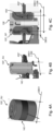
- Fig. 1A shows a bearing 100 of a compressor assembly 400 according to the concept of the invention.
- the bearing 100 comprises a bellow 120, adapted to mechanically connect, in particular to fix in a damping manner, a mounting bracket 430 of a compressor housing 420 to a (not shown) housing structure 910 of an air supply unit 900.
- the bearing 100 comprises a fixation feature 160 in the form of a hollow cylindrical body 162.
- the hollow cylindrical body 162 comprises in its center a cylindrical gas passage 163, adapted to pneumatically connect an inner bellow space 126 of the bellow 120 to a charging line 940, in particular a compressor line 942, of the air supply unit 900.
- the bellow 120 comprises a pressure port 150 on a second, supply unit-side bellow end face 180, which is located at the gas passage 163 of the fixation feature 160.
- a bellow skin 122 of the bellow 120 is held by the fixation feature 160, here the hollow cylindrical body 162, by means of clamping.
- a rotationally symmetrical web 165 of the hollow cylindrical body 162 is bent inwards in order to engage with and/or positively lock and/or force close the bellow skin 122.
- the bellow 128 is rotationally symmetrical with respect to an axial direction AA.
- the bellow 120 On a compressor-side bellow end face 178, located opposite of the supply unit-side bellow end face 180, the bellow 120 comprises a mounting feature 130.
- the mounting feature 130 is adapted to receive a radially and outwardly extending mounting shoulder 432 of the mounting bracket 430.
- the mounting shoulder 432 can be inserted into the mounting feature 130, which here comprises a recess 132 in the form of a rotationally symmetric recess 134.
- the rotationally symmetric recess 134 has the shape of a negative frustoconical recess 134.1.
- the flexibility of the bellow 120 decreases due to the increased pressure inside and the shape of the bellow 120 is stiffened as a consequence. Due to the shape of the negative frustoconical recess 134.1, in particular the fact that a recess diameter DR increases towards the inside of the bellow 120, and a corresponding shape of the mounting shoulder 432, said mounting shoulder 432 will be positively locked in said rotationally symmetric recess 134 once the bellow 120 is charged to its pressurized state SP.
- Fig. 1B shows a bearing 100 similar to the one shown in Fig. 1 A .
- the bearing 100 is shown in a mounted state, mechanically connected to a housing structure 910 of an air supply unit 900.
- the mechanical connection is established via there threaded surface 164 of the hollow cylindrical body 162 engaging with a bearing thread 916 of the housing structure 910, wherein the bearing thread 916 is located at a mounting receptacle 920 of the housing structure 910.
- the housing structure 910 further comprises a charging line 940, wherein the charging line 940 is pneumatically connected to the inner bellow space 126 via the mounting receptacle 920 for charging the bellow 120 from an unpressurized state SU to a pressurized state SP.
- the charging line 940 can particularly be a compressor line 942, pneumatically connecting the inner bellow space 126 to a pressure outlet 950 of the compressor 410. Via such compressor line 942, the bellow 120 can be charged from an unpressurized state SU into its pressurized state SP directly by the compressor 410 of the air supply unit 900, mounted by the bearing 100.
- the inner bellow space 126 is filled with a gaseous medium 200, in particular air 202, flowing in a flow direction DF from the charging line 940 to the inner bellow space 126.
- the air 202 can be provided by the compressor 410 in form of pressurized air DL.
- the housing structure 910 in particular a mounting receptacle 920, or the bearing 100, in particular the hollow cylindrical body 160 and/or the pressure port 150, can comprise a valve 460 for controlling the flow of the gaseous medium 200 into the inner bellow space 126 or out of it.
- the valve 460 can be a check valve 462, allowing a flow of the gaseous medium 200 in the flow direction DF, and blocking the flow in the opposite direction.
- Fig. 2 shows a second embodiment of a bearing 100' according to the concept of the invention.
- the mounting feature 130' of a bellow 120' of the bearing 100' comprises a recess 132' in the form of a rotationally symmetric recess 134, in particular a cylindrical recess 134.2.
- the mounting feature 130' further comprises a mounting assembly 136 with a mounting screw 138 and a mounting nut 140.
- the mounting assembly 136 establishes a mechanical connection between the bellow 120' and the mounting assembly 136 by means of clamping, by tightening the mounting screw 138 to the mounting nut 140 and therefore exerting a compression force FC onto the bellow skin 122.
- the mounting screw 138 is first inserted through the pressure port 150 of the bearing 100' in an unmounted state, and further through a clamping orifice 124 the mounting screw 138 comprises a screw head 138.1 and/or a washer 138.2 with a diameter greater than the diameter of the clamping orifice 124.
- the mounting nut 140 comprises a hollow cylindrical shaft 140.1 with an inner thread 140.2 adapted to engage with the mounting screw 138 such that, in a fastened state of the mounting assembly 136, the bellow skin 122 of the bellow 120 is clamped tightly in between the screw had 138.1 or washer 138.2 and the shaft 140.1.
- the mounting bracket 430' After mounting of the mounting assembly 136 and before charging the bellow 120', the mounting bracket 430' is held loosely between the mounting nut 140 and the bellow 120'.
- the axial dimension of the mounting nut 140 along the axial direction AA as well as the axial dimension of the recess 132 of the bellow 120' is selected such that the bellow 120, upon being charged in its pressurized state SP, will firmly press the mounting bracket 430' against the mounting nut 140, establishing a positive locking of the mounting bracket 430'.
- Said charging of the bellow 120' can be achieved via a charging line 940, analogously to the previously shown embodiment.
- the hollow cylindrical shaft 140.1 of the mounting nut 140 can be separate from the mounting nut 140 as a single part or also can be attached to the mounting bracket 430'.
- the hollow cylindrical shaft 140.1 of a mounting nut 140' can be of a defined axial length which limits the extent to which the mounting screw 138' can be fastened and thus defines a minimum axial extension of the bellow 120".
- Fig. 3A shows a third embodiment of the bearing 100" according to the concept of the invention.
- the bearing 100" comprises a bellow 120" which is airtight and therefore does not comprises a pressure port or the like gas passage.
- An inner bellow space 126' is filled with a gaseous medium 200, in particular an inert gas 204.
- An inert gas 204 has the advantage of reducing temperature influences to the bellow, in particular increasing the resistance to freezing.
- the bellow 120" comprises a mounting feature 130", which comprises a recess 132 in the form of an outer circumferential recess 134.3 and is adapted to receive a mounting bracket 430" of a compressor assembly 400.
- the outer circumferential recess 134.3 is adapted to hold the mounting bracket 430" in a positively locking manner when the bellow 120" is in its pressurized state SU.
- a fixation feature 160' comprises a mounting assembly 136', wherein the mounting assembly 136' comprises a mounting screw 138' and a mounting nut 140'.
- the fixation feature 160' further comprises a rotationally symmetric recess 134 in the form of a cylindrical through hole 134.4.
- the cylindrical through hole 134.4 is adapted to receive the mounting assembly 136' in order to mechanically connect, in particular fix, the bellow 120" to a mounting receptacle 920 of a housing structure 910 of an air supply unit 900.
- the mounting assembly 136' is further adapted to charge the bellow 120" from an unpressurized state SU to a pressurized state SP by fastening the mounting nut 140' to the mounting screw 138' and thus compressing the bellow 120" by reducing the axial distance between the mounting nut 140', in particular a mounting nut flange 140.2, and the mounting screw 138', in particular a mounting screw head 138.1.
- the concept of pneumatically charging the bellow 120 is realized by a mechanical compression imposed on the bellow 120" in the form of a compression force FC by the mounting assembly 136', achieved by fastening said mounting assembly 136.
- an unpressurized outer bellow diameter DBO1 is equal to or smaller than an inner bracket diameter DBI of a bracket orifice 434 of the mounting bracket 430", such that the bellow 120" can be inserted into said bracket orifice 434.
- the unpressurized outer bellow diameter DBO1 can also be slightly greater than the inner bracket diameter DBI, as long as, due to the flexibility of the bellow 120", it can be inserted into the bracket orifice 434.
- Fig. 3B shows a fourth embodiment of a bearing 100′′′ which differs from the third embodiment in particular in that a mounting assembly 136" of a fixation feature 160" comprises a first mounting screw washer 138.2A and a second mounting screw washer 138.2B.
- a mounting screw 138" comprises a mounting screw head 138.1' and is adapted to directly engage with a thread of a mounting receptacle 920' (not shown) of a housing structure 910 of an air supply unit 900.
- Both mounting screw washers 138.1A, 138.1B feature a washer diameter DW which is equal to or greater than a pressurized outer bellow diameter DBO2 of the bellow 120′′′.
- the first mounting screw washer 138.2A completely covers a first, upper bellow end face 178' and the second mounting screw washer 138.2B completely covers a second, supply unit - side bellow end face 180' of the bellow 120′′′.
- the compression force FC exerted on the bellow 120′′′ by the mounting assembly 136" can be equally distributed across the complete bellow end faces 178', 180' when the bellow 120′′′ is pneumatically charged by fastening the mounting assembly 136".
- Such mounting screw washers can also be applied in other embodiments, e.g. the one shown in Fig. 3A , for achieving a more equal force distribution, and are particularly advantageous for embodiments comprising an air tight bellow.
- a mounting feature 130, 130', 130" can comprise a feature marking 142 as a means of guidance for the assembly process.
- the feature marking 142 of the outer circumferential recess 134.3 comprises a colored circumferential zone which has to be brought into alignment with a bracket orifice (not shown here, see e.g. Fig. 3A ) prior to charging the bellow 120′′′ into its pressurized state SP.
- FIGS 4A to 4C demonstrate the process of assembling a bearing according to the concept of the invention with an airtight bellow 120".
- the bellow 120" is shown in its unassembled and unpressurized state SU, featuring an outer bellow diameter DBOL.
- Fig. 4B shows the process of inserting the bellow 120" into a bracket orifice 434 of a mounting bracket 430".
- a mounting assembly 136' can be inserted into the bellow 120 and can be fastened in order to charge the bellow 120" from an unpressurized state SU into a pressurized state SP, as shown in Fig. 4C .
Landscapes
- Engineering & Computer Science (AREA)
- Mechanical Engineering (AREA)
- General Engineering & Computer Science (AREA)
- Transportation (AREA)
- Physics & Mathematics (AREA)
- Acoustics & Sound (AREA)
- Aviation & Aerospace Engineering (AREA)
- Chemical & Material Sciences (AREA)
- Combustion & Propulsion (AREA)
- Compressor (AREA)
- Fluid-Damping Devices (AREA)
Claims (15)
- Ensemble compresseur (400) pour une unité d'alimentation en air (900) d'un véhicule (1000), comprenant :- un compresseur (410) pour fournir de l'air sous pression (DL), avec un carter de compresseur (420),- au moins un support de montage (430), dans lequel l'au moins un support de montage (430) est fixé au carter de compresseur (420),- pour chaque support de montage (430), un palier (100), destiné à relier l'ensemble compresseur (400) à une structure de boîtier (910) de l'unité d'alimentation en air (900),caractérisé en ce que- le palier (100) comprend un soufflet souple et creux (120), conçu pour recevoir un fluide gazeux (200), dans lequel le soufflet (120) comprend- au moins un élément de montage (130, 130', 130"), en particulier un évidement (132, 134, 134.1, 134.2, 134.3, 134.4), conçu pour recevoir le support de montage (430), et- le soufflet (120) est conçu pour être chargé pneumatiquement depuis un état sans pression (SU) à un état sous pression (SP), dans lequel- l'élément de montage (130, 130', 130") est conçu pour relier mécaniquement le soufflet (120) au support de montage (420) dans un état sous pression (SP) au moyen d'un verrouillage positif (PL).
- Ensemble compresseur (400) selon la revendication 1, comprenant un élément de fixation (160) conçu pour relier mécaniquement le soufflet (120) à la structure de boîtier (910) de l'unité d'alimentation en air (900).
- Ensemble compresseur (400) selon la revendication 1 ou 2, comprenant un ensemble de montage (136, 136', 136") avec une vis de montage (138), en particulier avec un écrou de montage (140), conçu pour exercer une force de compression axiale (FC) sur le soufflet (120) ou sur une peau de soufflet (122) du soufflet (120) en serrant la vis de montage (138) et/ou l'écrou de montage (140).
- Ensemble compresseur (400) selon la revendication 3,
caractérisé en ce que l'ensemble de montage (136, 136', 136") fait partie de l'élément de fixation (160) et est conçu pour charger le soufflet (120) depuis un état sans pression (SU) à un état sous pression (SP). - Ensemble compresseur (400) selon la revendication 3,
caractérisé en ce que l'ensemble de montage (136, 136', 136") fait partie de l'élément de montage (130, 130', 130") et est conçu pour serrer la peau de soufflet (122) au moyen d'une fermeture forcée, en particulier pour serrer de manière étanche la peau de soufflet (122) au niveau d'un orifice de serrage (124) situé dans l'élément de montage (130). - Ensemble compresseur (400) selon l'une des revendications 3 à 5, caractérisé en ce que l'ensemble de montage (136, 136', 136") comprend au moins une rondelle de vis de montage (138.2, 138.2A, 138.2B) conçue pour répartir la force de compression (FC) sur le soufflet (120) en particulier sur une face d'extrémité de soufflet (178, 180) du soufflet (120).
- Ensemble compresseur (400) selon l'une des revendications précédentes, caractérisé en ce que le soufflet (120) est étanche à l'air.
- Ensemble compresseur (400) selon l'une des revendications précédentes, caractérisé en ce que le soufflet (120) comprend un orifice de pression (150), conçu pour recevoir le fluide gazeux (200) pour charger pneumatiquement le soufflet (120) dans son état sous pression (SP).
- Ensemble compresseur (400) selon l'une des revendications 2 à 8, caractérisé en ce que l'élément de fixation (160) comprend- un corps cylindrique creux (162) avec une surface filetée (164), conçu pour venir en prise avec un filetage de palier correspondant (916) de la structure de boîtier (910), et- le corps cylindrique creux (162) est conçu pour maintenir le soufflet (120) au moyen d'une fixation par serrage et/ou par verrouillage positif.
- Ensemble compresseur (400) selon la revendication 8 ou 9, comprenant en outre une soupape (460), conçue pour fermer et ouvrir pneumatiquement l'orifice de pression (150) et/ou la liaison pneumatique entre la conduite de charge (940) et le soufflet (120).
- Ensemble compresseur (400) selon la revendication 10, dans lequel la soupape (460) est un clapet anti-retour (462), conçu pour s'ouvrir dans un sens d'écoulement (DF) allant de la conduite de charge (940) vers le soufflet (120), et pour se fermer dans le sens opposé.
- Ensemble compresseur (400) selon l'une des revendications précédentes, caractérisé en ce que le soufflet (120) est constitué de caoutchouc (128).
- Unité d'alimentation en air (900) pour un véhicule (1000), comprenant- un ensemble compresseur (400) selon l'une des revendications précédentes,- une structure de boîtier (910) avec au moins un logement de montage (920) conçu pour recevoir l'au moins un palier à soufflet (100).
- Unité d'alimentation en air (900) selon la revendication 13,
caractérisée en ce que la structure de boîtier (910) comprend une conduite de charge (940), en particulier une conduite de compresseur (942), conçue pour relier pneumatiquement une sortie de pression (450), en particulier de l'ensemble compresseur (400), à l'orifice de pression (150) du palier à soufflet (100). - Unité d'alimentation en air (900) selon la revendication 14,
caractérisée en ce qu'une soupape (460, 462) est située dans la conduite de charge (940), dans laquelle la soupape (460, 462) est conçue pour fermer et ouvrir pneumatiquement l'orifice de pression (150) et/ou la liaison pneumatique entre la conduite de charge (940) et le soufflet (120).
Applications Claiming Priority (1)
| Application Number | Priority Date | Filing Date | Title |
|---|---|---|---|
| PCT/EP2020/074384 WO2022048734A1 (fr) | 2020-09-02 | 2020-09-02 | Ensemble compresseur, unité d'alimentation en air |
Publications (2)
| Publication Number | Publication Date |
|---|---|
| EP4208375A1 EP4208375A1 (fr) | 2023-07-12 |
| EP4208375B1 true EP4208375B1 (fr) | 2025-01-01 |
Family
ID=72432871
Family Applications (1)
| Application Number | Title | Priority Date | Filing Date |
|---|---|---|---|
| EP20768532.2A Active EP4208375B1 (fr) | 2020-09-02 | 2020-09-02 | Ensemble compresseur, unité d'alimentation en air |
Country Status (4)
| Country | Link |
|---|---|
| US (1) | US12270446B2 (fr) |
| EP (1) | EP4208375B1 (fr) |
| CN (1) | CN116018295B (fr) |
| WO (1) | WO2022048734A1 (fr) |
Family Cites Families (26)
| Publication number | Priority date | Publication date | Assignee | Title |
|---|---|---|---|---|
| HU174666B (hu) * | 1977-06-30 | 1980-03-28 | Autoipari Kutato Intezet | Amortizator s vozdushnoj pruzhinoj i teleskopicheskim gasitelem kolebanij k avtomashinam dlja amortizacii kolebanij v zavisimosti ot nagruzki |
| DE3819770A1 (de) * | 1988-06-10 | 1989-12-14 | Brumme Kg Effbe Werk | Luftfederelement |
| US5964579A (en) * | 1997-06-24 | 1999-10-12 | Rheem Manufacturing Company | Prestressed resilient compressor mount apparatus |
| JP4230014B2 (ja) | 1997-09-25 | 2009-02-25 | 株式会社デンソー | 電動圧縮機の取付構造 |
| CA2264401C (fr) * | 1998-05-11 | 2003-01-28 | Rheem Manufacturing Company | Appareil pour installer un support precontraint de compresseur et methodes connexes |
| US6698730B2 (en) * | 2001-10-04 | 2004-03-02 | Bfs Diversified Products, Llc | Dual rate air spring |
| JP4339644B2 (ja) * | 2003-07-31 | 2009-10-07 | 株式会社フコク | 防振支持装置 |
| FR2867823B1 (fr) * | 2004-03-22 | 2006-07-14 | Cit Alcatel | Raccord amortisseur pour pompe a vide |
| DE102010054712B4 (de) * | 2010-12-16 | 2023-06-07 | Zf Cv Systems Hannover Gmbh | Druckluftversorgungsanlage und pneumatisches System |
| DE102011110975B4 (de) * | 2011-03-17 | 2015-08-13 | Volkswagen Aktiengesellschaft | Kraftübertragungselement mit einem in einer Hülle beweglichen Zugmittel, deren Übergangsbereich von einem flexiblen Balg eingeschlossen ist, sowie ein solcher Balg |
| JP5848198B2 (ja) * | 2012-06-14 | 2016-01-27 | 川崎重工業株式会社 | 軸ばねを備えた鉄道車両用台車 |
| DE102013003513A1 (de) * | 2013-03-04 | 2014-09-04 | Wabco Gmbh | Verdichteranordnung zum Betreiben einer Druckluftversorgungsanlage, Druckluftversorgungsanlage und Druckluftversorgungssystem sowie Fahrzeug mit einer solchen Druckluftversorgungsanlage |
| DE102014208901A1 (de) * | 2013-05-14 | 2014-11-20 | Schaeffler Technologies Gmbh & Co. Kg | Faltenbalg für Nehmerzylinder |
| US10005333B2 (en) * | 2013-05-28 | 2018-06-26 | Firestone Industrial Products Company, Llc | End member assemblies and travel-restraint assemblies as well as gas spring assemblies including same |
| JP2015090130A (ja) | 2013-11-07 | 2015-05-11 | サンデン株式会社 | 電動圧縮機の取付構造 |
| CN203879703U (zh) * | 2014-04-17 | 2014-10-15 | 洛阳北方易初摩托车有限公司 | 四轮休闲代步车车载空调的压缩机缓冲机构 |
| KR101512363B1 (ko) * | 2014-06-19 | 2015-04-16 | 대원강업주식회사 | 에어 베어링을 포함하는 에어 스프링 현가장치 |
| EP3177847B1 (fr) * | 2014-08-04 | 2024-04-03 | Firestone Industrial Products Company, LLC | Ensembles support et porte-joint, ainsi qu'ensembles éléments d'extrémité et ensembles ressort à gaz et amortisseur les comprenant |
| CN205174978U (zh) * | 2015-10-09 | 2016-04-20 | 合肥美的电冰箱有限公司 | 压缩机安装结构和具有其的冰箱 |
| CN106931684B (zh) * | 2015-12-29 | 2019-04-09 | 珠海格力电器股份有限公司 | 压缩机固定结构和空调器 |
| CN205401043U (zh) * | 2016-01-21 | 2016-07-27 | 珠海格力节能环保制冷技术研究中心有限公司 | 一种压缩机安装结构及采用其的空调器 |
| DE102017004088A1 (de) | 2017-04-28 | 2018-10-31 | Wabco Gmbh | Verdichter, Druckluftversorgungsanlage zum Betreiben einer Pneumatikanlage und Verfahren zum Betreiben einer Druckluftversorgungsanlage |
| DE102017128230A1 (de) * | 2017-11-29 | 2019-05-29 | Spaleck GmbH & Co. Kommanditgesellschaft | Lagereinrichtung für eine Schwingmaschine, Schwingmaschine und Verfahren zum Betreiben einer Schwingmaschine |
| KR102556979B1 (ko) * | 2018-07-02 | 2023-07-19 | 학교법인 두원학원 | 차량용 에어컨 압축기 진동 방지 구조 |
| CN209484103U (zh) * | 2018-12-24 | 2019-10-11 | 常州市常联波纹管有限公司 | 一种空气压缩机用排气波纹管 |
| CN211230757U (zh) * | 2019-12-18 | 2020-08-11 | 江苏车宜家新能源科技有限公司 | 一种压缩机用减震装置 |
-
2020
- 2020-09-02 EP EP20768532.2A patent/EP4208375B1/fr active Active
- 2020-09-02 WO PCT/EP2020/074384 patent/WO2022048734A1/fr not_active Ceased
- 2020-09-02 CN CN202080103913.XA patent/CN116018295B/zh active Active
-
2023
- 2023-03-02 US US18/177,542 patent/US12270446B2/en active Active
Also Published As
| Publication number | Publication date |
|---|---|
| WO2022048734A1 (fr) | 2022-03-10 |
| US12270446B2 (en) | 2025-04-08 |
| EP4208375A1 (fr) | 2023-07-12 |
| CN116018295A (zh) | 2023-04-25 |
| CN116018295B (zh) | 2025-06-10 |
| US20230234546A1 (en) | 2023-07-27 |
Similar Documents
| Publication | Publication Date | Title |
|---|---|---|
| CN107435675B (zh) | 用于调节运输工具中的至少一个流体流的装置 | |
| US7017890B2 (en) | Rubber bearing with anti-vibration system | |
| US11773939B2 (en) | Vibration absorber | |
| US12467305B2 (en) | Drive for adjusting an adjustment element of a motor vehicle | |
| US6135250A (en) | Hydropneumatic vibration damper of variable damping force | |
| KR20030019611A (ko) | 차량 브레이킹 시스템의 유압 유닛을 차량 내에탄력적으로 장착하기 위한 장치 | |
| CN103109096A (zh) | 无卡箍的卡紧接合部 | |
| JPH0791478A (ja) | 特に自動車用の調整可能な液圧式振動ダンパ | |
| US7644935B2 (en) | Spring carrier with adjustable spring collar | |
| CN103481885A (zh) | 具有旋转定位壳体的气压制动执行器室 | |
| US12270446B2 (en) | Compressor assembly, air supply unit | |
| JPH04224328A (ja) | 車両部分の受け口に組込まれた支持ブラケットの保安装置 | |
| US5895031A (en) | Hydraulically damping engine mounting | |
| US11401950B2 (en) | Pump housing having a fastening structure | |
| US6679508B2 (en) | Flexible no-lash drive plate | |
| US20230375038A1 (en) | Bearing assembly for bearing a device | |
| CN117189890A (zh) | 膨胀阀 | |
| KR101495390B1 (ko) | 구조 유닛 | |
| CN103832210A (zh) | 用于车辆驱动轴总成的中间支撑组件 | |
| EP4585823A1 (fr) | Dispositif anti-vibration | |
| US7097381B2 (en) | Joint | |
| US20050217113A1 (en) | Wheel bearing on an axle body for vehicles | |
| CN112292544B (zh) | 车辆总成-固定结构组合件和模块化系统 | |
| US20260132834A1 (en) | Apparatus for connecting a valve device to a vibration damper; vibration damper | |
| CN119222281B (zh) | 减振器上支撑的液压总成、减振器上支撑及其安装结构 |
Legal Events
| Date | Code | Title | Description |
|---|---|---|---|
| STAA | Information on the status of an ep patent application or granted ep patent |
Free format text: STATUS: UNKNOWN |
|
| STAA | Information on the status of an ep patent application or granted ep patent |
Free format text: STATUS: THE INTERNATIONAL PUBLICATION HAS BEEN MADE |
|
| PUAI | Public reference made under article 153(3) epc to a published international application that has entered the european phase |
Free format text: ORIGINAL CODE: 0009012 |
|
| STAA | Information on the status of an ep patent application or granted ep patent |
Free format text: STATUS: REQUEST FOR EXAMINATION WAS MADE |
|
| 17P | Request for examination filed |
Effective date: 20230403 |
|
| AK | Designated contracting states |
Kind code of ref document: A1 Designated state(s): AL AT BE BG CH CY CZ DE DK EE ES FI FR GB GR HR HU IE IS IT LI LT LU LV MC MK MT NL NO PL PT RO RS SE SI SK SM TR |
|
| DAV | Request for validation of the european patent (deleted) | ||
| DAX | Request for extension of the european patent (deleted) | ||
| GRAP | Despatch of communication of intention to grant a patent |
Free format text: ORIGINAL CODE: EPIDOSNIGR1 |
|
| STAA | Information on the status of an ep patent application or granted ep patent |
Free format text: STATUS: GRANT OF PATENT IS INTENDED |
|
| INTG | Intention to grant announced |
Effective date: 20241021 |
|
| GRAS | Grant fee paid |
Free format text: ORIGINAL CODE: EPIDOSNIGR3 |
|
| GRAA | (expected) grant |
Free format text: ORIGINAL CODE: 0009210 |
|
| STAA | Information on the status of an ep patent application or granted ep patent |
Free format text: STATUS: THE PATENT HAS BEEN GRANTED |
|
| AK | Designated contracting states |
Kind code of ref document: B1 Designated state(s): AL AT BE BG CH CY CZ DE DK EE ES FI FR GB GR HR HU IE IS IT LI LT LU LV MC MK MT NL NO PL PT RO RS SE SI SK SM TR |
|
| REG | Reference to a national code |
Ref country code: GB Ref legal event code: FG4D |
|
| REG | Reference to a national code |
Ref country code: CH Ref legal event code: EP |
|
| REG | Reference to a national code |
Ref country code: DE Ref legal event code: R096 Ref document number: 602020044082 Country of ref document: DE |
|
| REG | Reference to a national code |
Ref country code: IE Ref legal event code: FG4D |
|
| REG | Reference to a national code |
Ref country code: LT Ref legal event code: MG9D |
|
| REG | Reference to a national code |
Ref country code: NL Ref legal event code: MP Effective date: 20250101 |
|
| REG | Reference to a national code |
Ref country code: AT Ref legal event code: MK05 Ref document number: 1755951 Country of ref document: AT Kind code of ref document: T Effective date: 20250101 |
|
| PG25 | Lapsed in a contracting state [announced via postgrant information from national office to epo] |
Ref country code: NL Free format text: LAPSE BECAUSE OF FAILURE TO SUBMIT A TRANSLATION OF THE DESCRIPTION OR TO PAY THE FEE WITHIN THE PRESCRIBED TIME-LIMIT Effective date: 20250101 |
|
| PG25 | Lapsed in a contracting state [announced via postgrant information from national office to epo] |
Ref country code: FI Free format text: LAPSE BECAUSE OF FAILURE TO SUBMIT A TRANSLATION OF THE DESCRIPTION OR TO PAY THE FEE WITHIN THE PRESCRIBED TIME-LIMIT Effective date: 20250101 |
|
| PG25 | Lapsed in a contracting state [announced via postgrant information from national office to epo] |
Ref country code: PL Free format text: LAPSE BECAUSE OF FAILURE TO SUBMIT A TRANSLATION OF THE DESCRIPTION OR TO PAY THE FEE WITHIN THE PRESCRIBED TIME-LIMIT Effective date: 20250101 |
|
| PG25 | Lapsed in a contracting state [announced via postgrant information from national office to epo] |
Ref country code: ES Free format text: LAPSE BECAUSE OF FAILURE TO SUBMIT A TRANSLATION OF THE DESCRIPTION OR TO PAY THE FEE WITHIN THE PRESCRIBED TIME-LIMIT Effective date: 20250101 |
|
| PG25 | Lapsed in a contracting state [announced via postgrant information from national office to epo] |
Ref country code: NO Free format text: LAPSE BECAUSE OF FAILURE TO SUBMIT A TRANSLATION OF THE DESCRIPTION OR TO PAY THE FEE WITHIN THE PRESCRIBED TIME-LIMIT Effective date: 20250401 Ref country code: IS Free format text: LAPSE BECAUSE OF FAILURE TO SUBMIT A TRANSLATION OF THE DESCRIPTION OR TO PAY THE FEE WITHIN THE PRESCRIBED TIME-LIMIT Effective date: 20250501 |
|
| PG25 | Lapsed in a contracting state [announced via postgrant information from national office to epo] |
Ref country code: HR Free format text: LAPSE BECAUSE OF FAILURE TO SUBMIT A TRANSLATION OF THE DESCRIPTION OR TO PAY THE FEE WITHIN THE PRESCRIBED TIME-LIMIT Effective date: 20250101 |
|
| PG25 | Lapsed in a contracting state [announced via postgrant information from national office to epo] |
Ref country code: LV Free format text: LAPSE BECAUSE OF FAILURE TO SUBMIT A TRANSLATION OF THE DESCRIPTION OR TO PAY THE FEE WITHIN THE PRESCRIBED TIME-LIMIT Effective date: 20250101 Ref country code: PT Free format text: LAPSE BECAUSE OF FAILURE TO SUBMIT A TRANSLATION OF THE DESCRIPTION OR TO PAY THE FEE WITHIN THE PRESCRIBED TIME-LIMIT Effective date: 20250502 |
|
| PG25 | Lapsed in a contracting state [announced via postgrant information from national office to epo] |
Ref country code: BG Free format text: LAPSE BECAUSE OF FAILURE TO SUBMIT A TRANSLATION OF THE DESCRIPTION OR TO PAY THE FEE WITHIN THE PRESCRIBED TIME-LIMIT Effective date: 20250101 Ref country code: GR Free format text: LAPSE BECAUSE OF FAILURE TO SUBMIT A TRANSLATION OF THE DESCRIPTION OR TO PAY THE FEE WITHIN THE PRESCRIBED TIME-LIMIT Effective date: 20250402 |
|
| PG25 | Lapsed in a contracting state [announced via postgrant information from national office to epo] |
Ref country code: AT Free format text: LAPSE BECAUSE OF FAILURE TO SUBMIT A TRANSLATION OF THE DESCRIPTION OR TO PAY THE FEE WITHIN THE PRESCRIBED TIME-LIMIT Effective date: 20250101 |
|
| PG25 | Lapsed in a contracting state [announced via postgrant information from national office to epo] |
Ref country code: CZ Free format text: LAPSE BECAUSE OF FAILURE TO SUBMIT A TRANSLATION OF THE DESCRIPTION OR TO PAY THE FEE WITHIN THE PRESCRIBED TIME-LIMIT Effective date: 20250101 |
|
| PG25 | Lapsed in a contracting state [announced via postgrant information from national office to epo] |
Ref country code: SE Free format text: LAPSE BECAUSE OF FAILURE TO SUBMIT A TRANSLATION OF THE DESCRIPTION OR TO PAY THE FEE WITHIN THE PRESCRIBED TIME-LIMIT Effective date: 20250101 |
|
| REG | Reference to a national code |
Ref country code: DE Ref legal event code: R097 Ref document number: 602020044082 Country of ref document: DE |
|
| PG25 | Lapsed in a contracting state [announced via postgrant information from national office to epo] |
Ref country code: SM Free format text: LAPSE BECAUSE OF FAILURE TO SUBMIT A TRANSLATION OF THE DESCRIPTION OR TO PAY THE FEE WITHIN THE PRESCRIBED TIME-LIMIT Effective date: 20250101 |
|
| PG25 | Lapsed in a contracting state [announced via postgrant information from national office to epo] |
Ref country code: DK Free format text: LAPSE BECAUSE OF FAILURE TO SUBMIT A TRANSLATION OF THE DESCRIPTION OR TO PAY THE FEE WITHIN THE PRESCRIBED TIME-LIMIT Effective date: 20250101 |
|
| PGFP | Annual fee paid to national office [announced via postgrant information from national office to epo] |
Ref country code: DE Payment date: 20250702 Year of fee payment: 6 |
|
| PG25 | Lapsed in a contracting state [announced via postgrant information from national office to epo] |
Ref country code: IT Free format text: LAPSE BECAUSE OF FAILURE TO SUBMIT A TRANSLATION OF THE DESCRIPTION OR TO PAY THE FEE WITHIN THE PRESCRIBED TIME-LIMIT Effective date: 20250101 |
|
| PGFP | Annual fee paid to national office [announced via postgrant information from national office to epo] |
Ref country code: GB Payment date: 20250703 Year of fee payment: 6 |
|
| PGFP | Annual fee paid to national office [announced via postgrant information from national office to epo] |
Ref country code: FR Payment date: 20250703 Year of fee payment: 6 |
|
| PG25 | Lapsed in a contracting state [announced via postgrant information from national office to epo] |
Ref country code: EE Free format text: LAPSE BECAUSE OF FAILURE TO SUBMIT A TRANSLATION OF THE DESCRIPTION OR TO PAY THE FEE WITHIN THE PRESCRIBED TIME-LIMIT Effective date: 20250101 |
|
| PG25 | Lapsed in a contracting state [announced via postgrant information from national office to epo] |
Ref country code: RO Free format text: LAPSE BECAUSE OF FAILURE TO SUBMIT A TRANSLATION OF THE DESCRIPTION OR TO PAY THE FEE WITHIN THE PRESCRIBED TIME-LIMIT Effective date: 20250101 |
|
| PG25 | Lapsed in a contracting state [announced via postgrant information from national office to epo] |
Ref country code: SK Free format text: LAPSE BECAUSE OF FAILURE TO SUBMIT A TRANSLATION OF THE DESCRIPTION OR TO PAY THE FEE WITHIN THE PRESCRIBED TIME-LIMIT Effective date: 20250101 |
|
| PLBE | No opposition filed within time limit |
Free format text: ORIGINAL CODE: 0009261 |
|
| STAA | Information on the status of an ep patent application or granted ep patent |
Free format text: STATUS: NO OPPOSITION FILED WITHIN TIME LIMIT |
|
| REG | Reference to a national code |
Ref country code: CH Ref legal event code: L10 Free format text: ST27 STATUS EVENT CODE: U-0-0-L10-L00 (AS PROVIDED BY THE NATIONAL OFFICE) Effective date: 20251112 |
|
| 26N | No opposition filed |
Effective date: 20251002 |
|
| REG | Reference to a national code |
Ref country code: CH Ref legal event code: H13 Free format text: ST27 STATUS EVENT CODE: U-0-0-H10-H13 (AS PROVIDED BY THE NATIONAL OFFICE) Effective date: 20260504 |