EP4208626B1 - Turbine einer turbomaschine mit verschleiss- und thermoschutzeinlage - Google Patents
Turbine einer turbomaschine mit verschleiss- und thermoschutzeinlage Download PDFInfo
- Publication number
- EP4208626B1 EP4208626B1 EP21770057.4A EP21770057A EP4208626B1 EP 4208626 B1 EP4208626 B1 EP 4208626B1 EP 21770057 A EP21770057 A EP 21770057A EP 4208626 B1 EP4208626 B1 EP 4208626B1
- Authority
- EP
- European Patent Office
- Prior art keywords
- foil
- foils
- turbine
- ring
- circumferential
- Prior art date
- Legal status (The legal status is an assumption and is not a legal conclusion. Google has not performed a legal analysis and makes no representation as to the accuracy of the status listed.)
- Active
Links
Images




Classifications
-
- F—MECHANICAL ENGINEERING; LIGHTING; HEATING; WEAPONS; BLASTING
- F01—MACHINES OR ENGINES IN GENERAL; ENGINE PLANTS IN GENERAL; STEAM ENGINES
- F01D—NON-POSITIVE DISPLACEMENT MACHINES OR ENGINES, e.g. STEAM TURBINES
- F01D25/00—Component parts, details, or accessories, not provided for in, or of interest apart from, other groups
- F01D25/08—Cooling; Heating; Heat-insulation
-
- F—MECHANICAL ENGINEERING; LIGHTING; HEATING; WEAPONS; BLASTING
- F01—MACHINES OR ENGINES IN GENERAL; ENGINE PLANTS IN GENERAL; STEAM ENGINES
- F01D—NON-POSITIVE DISPLACEMENT MACHINES OR ENGINES, e.g. STEAM TURBINES
- F01D11/00—Preventing or minimising internal leakage of working-fluid, e.g. between stages
- F01D11/005—Sealing means between non relatively rotating elements
-
- F—MECHANICAL ENGINEERING; LIGHTING; HEATING; WEAPONS; BLASTING
- F01—MACHINES OR ENGINES IN GENERAL; ENGINE PLANTS IN GENERAL; STEAM ENGINES
- F01D—NON-POSITIVE DISPLACEMENT MACHINES OR ENGINES, e.g. STEAM TURBINES
- F01D9/00—Stators
- F01D9/02—Nozzles; Nozzle boxes; Stator blades; Guide conduits, e.g. individual nozzles
- F01D9/04—Nozzles; Nozzle boxes; Stator blades; Guide conduits, e.g. individual nozzles forming ring or sector
- F01D9/042—Nozzles; Nozzle boxes; Stator blades; Guide conduits, e.g. individual nozzles forming ring or sector fixing blades to stators
-
- F—MECHANICAL ENGINEERING; LIGHTING; HEATING; WEAPONS; BLASTING
- F05—INDEXING SCHEMES RELATING TO ENGINES OR PUMPS IN VARIOUS SUBCLASSES OF CLASSES F01-F04
- F05D—INDEXING SCHEME FOR ASPECTS RELATING TO NON-POSITIVE-DISPLACEMENT MACHINES OR ENGINES, GAS-TURBINES OR JET-PROPULSION PLANTS
- F05D2260/00—Function
- F05D2260/30—Retaining components in desired mutual position
-
- F—MECHANICAL ENGINEERING; LIGHTING; HEATING; WEAPONS; BLASTING
- F05—INDEXING SCHEMES RELATING TO ENGINES OR PUMPS IN VARIOUS SUBCLASSES OF CLASSES F01-F04
- F05D—INDEXING SCHEME FOR ASPECTS RELATING TO NON-POSITIVE-DISPLACEMENT MACHINES OR ENGINES, GAS-TURBINES OR JET-PROPULSION PLANTS
- F05D2260/00—Function
- F05D2260/94—Functionality given by mechanical stress related aspects such as low cycle fatigue [LCF] of high cycle fatigue [HCF]
- F05D2260/941—Functionality given by mechanical stress related aspects such as low cycle fatigue [LCF] of high cycle fatigue [HCF] particularly aimed at mechanical or thermal stress reduction
-
- Y—GENERAL TAGGING OF NEW TECHNOLOGICAL DEVELOPMENTS; GENERAL TAGGING OF CROSS-SECTIONAL TECHNOLOGIES SPANNING OVER SEVERAL SECTIONS OF THE IPC; TECHNICAL SUBJECTS COVERED BY FORMER USPC CROSS-REFERENCE ART COLLECTIONS [XRACs] AND DIGESTS
- Y02—TECHNOLOGIES OR APPLICATIONS FOR MITIGATION OR ADAPTATION AGAINST CLIMATE CHANGE
- Y02T—CLIMATE CHANGE MITIGATION TECHNOLOGIES RELATED TO TRANSPORTATION
- Y02T50/00—Aeronautics or air transport
- Y02T50/60—Efficient propulsion technologies, e.g. for aircraft
Definitions
- the invention relates to turbomachines, in particular aircraft turbojets and turboprops.
- the turbomachine is a twin-spool turbomachine and comprises a fan, a low-pressure compressor, a high-pressure compressor, a combustion chamber, a high-pressure turbine and a low-pressure turbine.
- the low-pressure turbine comprises several successive stages, each comprising a downstream distributor and an upstream impeller.
- upstream and downstream are defined in relation to the direction of flow of the gases in the turbine.
- Each distributor comprises two radially internal and external coaxial annular platforms, between which blades extend.
- the distributor is attached to an external casing of the turbine.
- the external platform comprises at its upstream end two rims which extend on either side of an annular groove open upstream which form a spoiler equipped with a clamp. All of the distributors form the fixed part of the engine called the "stator".
- the various wheels are connected to a drive shaft so as to form the rotor of the turbine.
- Each wheel rotates inside a ring also attached to the external casing.
- This ring is formed of ring sectors which each internally carry a block of abradable material capable of cooperating by friction with annular lickers arranged on the periphery of the rotor blades.
- a downstream annular hook of the casing, forming a rail, and a downstream edge of the ring sectors are held in the spoiler.
- Anti-wear shims are arranged between the ring hook and the distributor.
- the shims each have a profiled shape in one direction circumferential to the axis and extend in succession in this direction.
- Each shim is housed in the spoiler by being interposed between the spoiler on the one hand and the hook and the edge of the ring on the other hand.
- These shims have a thermal protection and anti-wear function (this is to limit wear between the distributor and the crankcase hook).
- EP-2 368 016 discloses a turbine according to the preamble of claim 1.
- An aim of the invention is to avoid mutual overlapping of the foils.
- the invention provides a turbine for a turbomachine according to claim 1.
- the protrusions can come to bear against each other to prevent the foils from overlapping during assembly or during operation.
- the foils can therefore come to bear directly against each other.
- each foil includes reliefs or hollows configured to limit the movement of the foil in a circumferential direction.
- the protrusions of each foil are at least two in number, said protrusions of each foil extending in projection from a circumferential end of the foil.
- each foil there are at least two protuberances on at least one edge adjacent to another of the foils.
- At least one of the protrusions extends radially.
- the protrusions can be expected to be rounded.
- the ring comprises fingers passing through the spoiler of the distributor, each foil having at least one recess capable of coming to bear circumferentially against one of the fingers.
- the fingers block the ring in circumferential rotation relative to the distributor. This time, the foils bear against the ring.
- the anti-rotation function already associated with the fingers is used to prevent the foils from overlapping.
- the recess may be provided to extend from a circumferential end of the foil.
- each foil comprises two recesses, each recess extending to an opposite circumferential end of the foil.
- the ring is formed of ring sectors arranged in succession in the circumferential direction and separated two by two by circumferential junction zones of the ring sectors, the foils also being two by two circumferentially separated from each other by foil junction zones, the foil junction zones being offset in the circumferential direction relative to the circumferential junction zones of the ring sectors.
- the invention also provides a turbomachine such as an aircraft turboprop or turbojet, comprising at least one turbine according to the invention.
- the turbomachine has a main axis X-X which serves as the axis of rotation of the rotor relative to the stator.
- the low-pressure turbine 12 comprises several successive stages, each comprising a downstream distributor 14 and an upstream impeller 16. All of the distributors 14 belong to the fixed part of the engine forming the stator which also comprises an external casing 20.
- Each distributor 14 comprises a radially inner annular platform and a radially outer annular platform 18 coaxial, between which extend radial or substantially radial blades with reference to the axis X-X, regularly spaced over the entire circumference of the platforms.
- the distributor 14 is attached radially outwards to the external casing 20.
- the external annular platform 18 comprises at its upstream end a radially external rim (or finger) 22 and a radially internal rim (or finger) 24 which both extend upstream. These two rims define between them an annular groove 26 open upstream. They form a spoiler provided with a clamp thus having two jaws or jaws.
- Each impeller 16 comprises a disk carrying at its external periphery radial or substantially radial blades 28, the disks of the different wheels being connected coaxially to each other and to a drive shaft by suitable means, so as to form the rotor of the turbine.
- the impeller 16 rotates inside a ring 30.
- This ring is formed of several ring sectors 32, which extend in a circle in the circumferential direction to the axis, and which are arranged end to end in the same direction. They each carry internally a block of abradable material 34. These blocks are capable of cooperating by friction with annular wipers arranged at the radially external periphery of each blade 28 of the rotor.
- each ring sector 32 comprises at its downstream end an annular groove sector open radially outwards.
- the groove sectors together form an annular groove 36 in which a downstream hook 38 of the external casing is engaged, thus ensuring the fixing of the ring 30 on the casing.
- the hook has the profiled shape of an annular rail.
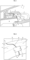
- the hook 38 and the downstream ends of the ring sectors 32 are held in a radial direction (i.e. from bottom to top and from top to bottom on the figure 1 ) by the internal 24 and external 26 edges of the external platform 18.
- This clamp presses the hook 38 and the ring 30 in the radial direction and holds them in the groove 26 of the spoiler. It mounts the ring against the crankcase hook.
- the turbomachine also comprises anti-wear shims 40.
- the shims 40 each have a chute shape, profiled in the circumferential direction to the axis X-X. They extend in succession in this direction. In this way, just like the ring sectors 32, they form an assembly with symmetry of revolution around the axis.
- each foil 40 is in the form of a chute and comprises a flat bottom 52 perpendicular to the axis XX, a radially external cylindrical wall 54 and a radially internal cylindrical wall 56. It is arranged in the groove 26 so that its external wall 54 is in contact with the radially internal face of the external finger 22 and its internal wall 56 is in contact with the radially external face of the internal finger 24.
- Each foil thus has, in radial section, as illustrated in figure 1 , a general asymmetrical “U” shape, just like that of the groove 26 of the spoiler.
- Each shim 40 extends into the spoiler 22, 24 by being interposed between the latter on the one hand and the hook 38 and the edge of the ring 30 on the other hand.
- Each shim extends radially over the entire clamp of the spoiler, namely both on the external finger 22 of the clamp and on its internal finger 24.
- the shim 40 has a radially external end 58 curved towards the outside of the turbine, such that it extends in front of the upstream face of the radially external finger 22. It also has a radially internal end 60 curved towards the inside of the turbine and which extends opposite the upstream face of the radially internal finger 24. These ends 58, 60 ensure the axial locking of the shim.
- the two free ends of the section of the shim form two respective lips which emerge from the groove and which are curved in opposite directions to each other, one in the direction of the axis and the other in the direction opposite the axis.
- the turbine comprises stops 162 against a movement of the foils 40 in the circumferential direction relative to each other.
- each foil 40 protuberances or ears 162 which form the stops and are arranged so that the protuberances of two circumferentially adjacent foils extend opposite one another.
- the protuberances 162 extend in projection from each longitudinal end edge 64 of the foil facing the circumferentially adjacent foil 40.
- the protuberances here have a half-disc shape but other shapes such as a rectangular or square shape would also be conceivable.
- the protuberances 162 are here folded to extend in a plane inclined relative to the local plane of the foil and relative to the circumferential direction. Each protuberance 162 therefore extends in projection from one face of the foil.
- the protrusions 162 are two in number on each edge 64 adjacent to another of the foils. Furthermore, in this case, on each edge, one of the protrusions 162 is oriented towards the axis and towards the upstream, so that it is radial, and the other is oriented towards the downstream.
- the first extend from a wall of the foil located between the bottom 52 and the external wall 54.
- the second extend from the bottom 52.
- Each foil 40 is symmetrical with respect to a radial plane passing through the center of the foil.
- the protuberance 162 of the foil oriented towards the axis is directly opposite a protuberance of the adjacent foil having the same orientation. It can therefore come into abutment against it to prevent the two adjacent foils from overlapping each other, during assembly or in operation. The same applies in an analogous manner to the protuberance oriented in the downstream direction.
- the stops 162 form means for placing the shims in circumferential position relative to each other. In operation, they prevent the rotation of each shim 40 around the axis of the turbine relative to the other shims.
- the ring 30 was formed of sectors 32 arranged in succession in the circumferential direction. They are separated from each other by junction zones 67 of the sectors.
- the foils 40 are similarly separated from each other by junction zones 66 of the foils. The latter are offset in the circumferential direction relative to the junction zones 67 of the sectors. In other words, the junctions of the two groups are not coincident. In this way, the pressure losses are increased during the passage of gases between the ring sectors 32 and then between the foils 40 for better insulation.
- each foil 40 is made of a thin sheet, for example with a thickness of less than 1 mm, which gives it a certain elasticity. It can be made of an alloy that is particularly resistant to wear and thermal stresses, such as an alloy based on cobalt and/or nickel.
- the crankcase hooks or rails 38 remain relatively cool and are insulated as much as possible from the spoilers of the distributors whose temperatures are close to the temperature of the aerodynamic vein.
- the foils 40 make it possible to limit the thermal conduction between these parts. In addition, they limit the temperature of the spoiler of the distributor by protecting it from the air flow which passes between the ring sectors.
- the bottom 52 of the foil 40 in fact constitutes a sealing barrier for the gas which cannot flow between the downstream end of the sealing ring and the groove 26 of the distributor.
- This embodiment is particularly suitable in configurations where the ring 30 does not have any anti-rotation means cooperating directly with the opposite distributor.
- the ring 30 comprises fingers 68 penetrating into housings of the distributor 14 in the axial direction, downstream, and coming if necessary to bear against the distributor in the circumferential direction.
- the fingers 68 are distributed on the ring in the circumferential direction. They have for example a profiled shape, flattened in the radial direction and a rectangular section in a plane perpendicular to the axis. But other shapes are conceivable.
- Each foil 40 has two recesses 262 each capable of coming to bear against one of the fingers 68 in the circumferential direction.
- each recess 262 extends from a respective longitudinal end edge 64 of the foil located opposite a similar edge 64 of the adjacent foil.
- the number of recesses 262 is two on each foil, the recesses extending into opposite edges of the foil.
- the recesses are here provided in the bottom 52 of the foil.
- each foil is symmetrical with respect to a plane radial to the axis passing through its center.
- the two recesses or notches 262 of the circumferentially adjacent shims together form a rectangular housing allowing the passage of the respective finger 68 of the ring, as illustrated in figure 6 .
- the finger and the recesses ensure the correct positioning of the shims when they are mounted in the turbomachine.
- the fingers prevent overlapping in the circumferential direction of the shims by forming a stop for them in the circumferential direction.
- the assembly can take place as follows. It is assumed that the distributor 14 is also divided into sectors which follow one another in the circumferential direction and whose number is equal to the number of shims 40. It is expected that the shims are associated with the respective distributor sectors. It is therefore possible to mount each shim in contact with the corresponding distributor sector, then install each subassembly thus formed separately in the turbomachine. The shims then ensure good mutual positioning of the distributor sectors in the circumferential direction.
- the invention makes it possible to avoid any overlap in the circumferential direction or damage if these subassemblies are assembled in the turbomachine blindly, that is to say in a configuration where the distributor hides from the operator's view the ring 30 already installed and the shim 40 which is not visible when it is installed. This is the case, for the arrangement not covered by the invention, in the configuration of the figure 7 on which the distributor 14 is shown in transparency in order to show the foils 40 and the ring 30.
- the anti-rotation function of the 40 shims is also useful in operation in order to avoid overlaps in the circumferential direction under the effect of slight tangential movements of the distributors.
- the turbomachine may include other means of thermal insulation and sealing, in addition to the foils.
- the stops preventing the overlapping of the foils in the circumferential direction may take other forms than those presented above. Their number and arrangement on each foil may vary.
Landscapes
- Engineering & Computer Science (AREA)
- Mechanical Engineering (AREA)
- General Engineering & Computer Science (AREA)
- Turbine Rotor Nozzle Sealing (AREA)
Claims (10)
- Turbine (12) für eine Turbomaschine (100; 200), die sich um eine Hauptachse (X-X) erstreckt und umfasst:- ein Gehäuse (4), das einen ringförmigen Haken (38) umfasst,- ein beweglich angebrachtes Rad (16),- einen Ring (30), der sich dem Rad (16) zugewandt gemäß einer radialen Richtung der Hauptachse (X-X) erstreckt,- einen Verteiler (14), der eine Schaufel umfasst, die mit einer Plattform (18) versehen ist, wobei die Plattform (18) radial nach außen durch eine Anlage (22, 24) verlängert ist, wobei die Anlage (22, 24) radial an dem Haken (38) des Gehäuses (4) angebracht ist, und- Lamellen (40), die jeweils eine rinnenförmige Profilform gemäß einer Umfangsrichtung zur Achse aufweisen, wobei sich die Lamellen (40) aufeinanderfolgend gemäß der Umfangsrichtung erstrecken, wobei sich jede Lamelle (40) zwischen der Anlage (22, 24) und dem Haken (38) erstreckt, wobei die Turbine Anschläge (162; 262) entgegen einer Verlagerung der Lamellen (40) gemäß der Umfangsrichtung umfasst,dadurch gekennzeichnet, dass jede Lamelle (40) einen Vorsprung (162) umfasst, der so angeordnet ist, dass er sich umfangmäßig einem anderen Vorsprung (162) einer anderen, umfangmäßig benachbarten Lamelle (40) zugewandt erstreckt.
- Turbine nach vorhergehendem Anspruch, wobei jede Lamelle Erhebungen (162) oder Vertiefungen (262) umfasst, die so ausgelegt sind, dass sie die Verlagerung der Lamelle gemäß einer Umfangsrichtung begrenzen.
- Turbine nach einem der vorhergehenden Ansprüche, wobei die Vorsprünge (162) jeder Lamelle (40) mindestens zwei sind, wobei sich die Vorsprünge (162) jeder Lamelle (40) von einem Umfangsende der Lamelle (40) vorspringend erstrecken.
- Turbine nach einem der vorhergehenden Ansprüche, wobei sich auf jeder Lamelle (40) mindestens einer der Vorsprünge (162) in radialer Richtung erstreckt.
- Turbine nach einem der vorhergehenden Ansprüche, wobei die Vorsprünge (162) abgerundet sind.
- Turbine nach einem der vorhergehenden Ansprüche, wobei der Ring (30) Finger (68) aufweist, die die Anlage (22, 24) des Verteilers (14) durchqueren, wobei jede Lamelle (40) mindestens eine Aussparung (262) aufweist, die geeignet ist, umfangmäßig an einem der Finger (68) in Anlage zu kommen.
- Turbine nach Anspruch 6, wobei sich die Aussparung (262) ab einem Umfangsende (64) der Lamelle (40) erstreckt.
- Turbine nach einem der Ansprüche 6 oder 7, wobei jede Lamelle (40) zwei Aussparungen (262) umfasst, wobei sich jede Aussparung (262) an einem umfangmäßig gegenüberliegenden Ende (64) de Lamelle (40) erstreckt.
- Turbine nach einem der vorhergehenden Ansprüche, wobei der Ring (30) aus Ringsektoren gebildet ist, die gemäß der Umfangsrichtung hintereinander angeordnet sind und jeweils paarweise durch Umfangsverbindungsbereiche (67) der Ringsektoren voneinander getrennt sind, wobei die Lamellen (40) ebenfalls paarweise umfangmäßig durch Verbindungsbereiche (66) der Lamellen (40) voneinander getrennt sind, wobei die Verbindungsbereiche (66) der Lamellen (40) in Umfangsrichtung relativ zu den Umfangsverbindungsbereichen (67) der Ringsektoren versetzt sind.
- Turbomaschine wie ein Turboprop- oder Turbostrahltriebwerk (100; 200) eines Luftfahrzeugs, umfassend mindestens eine Turbine (12) nach mindestens einem der vorhergehenden Ansprüche.
Applications Claiming Priority (2)
| Application Number | Priority Date | Filing Date | Title |
|---|---|---|---|
| FR2009012A FR3113923B1 (fr) | 2020-09-04 | 2020-09-04 | Turbine pour turbomachine comprenant des clinquants de protection thermique |
| PCT/FR2021/051489 WO2022049338A1 (fr) | 2020-09-04 | 2021-08-26 | Turbine pour turbomachine comprenant des clinquants de protection thermique |
Publications (2)
| Publication Number | Publication Date |
|---|---|
| EP4208626A1 EP4208626A1 (de) | 2023-07-12 |
| EP4208626B1 true EP4208626B1 (de) | 2024-10-23 |
Family
ID=73139019
Family Applications (1)
| Application Number | Title | Priority Date | Filing Date |
|---|---|---|---|
| EP21770057.4A Active EP4208626B1 (de) | 2020-09-04 | 2021-08-26 | Turbine einer turbomaschine mit verschleiss- und thermoschutzeinlage |
Country Status (5)
| Country | Link |
|---|---|
| US (1) | US11965426B2 (de) |
| EP (1) | EP4208626B1 (de) |
| CN (1) | CN116018448A (de) |
| FR (1) | FR3113923B1 (de) |
| WO (1) | WO2022049338A1 (de) |
Families Citing this family (2)
| Publication number | Priority date | Publication date | Assignee | Title |
|---|---|---|---|---|
| FR3149037A1 (fr) * | 2023-05-26 | 2024-11-29 | Safran Aircraft Engines | Ensemble pour turbomachine comprenant un élément d’étanchéité et élément d’étanchéité pour un tel ensemble pour turbomachine |
| CN120251557B (zh) * | 2025-06-09 | 2025-08-19 | 中国航发四川燃气涡轮研究院 | 一种压气机内环周向止动结构及其安装方法 |
Citations (1)
| Publication number | Priority date | Publication date | Assignee | Title |
|---|---|---|---|---|
| EP2368016B1 (de) * | 2008-11-26 | 2016-10-12 | Safran Aircraft Engines | Verschleissschutzvorrichtung für die schaufeln eines leitschaufelträgers in einem turbinentriebwerk in der aeronautik |
Family Cites Families (12)
| Publication number | Priority date | Publication date | Assignee | Title |
|---|---|---|---|---|
| US4856963A (en) * | 1988-03-23 | 1989-08-15 | United Technologies Corporation | Stator assembly for an axial flow rotary machine |
| GB2477825B (en) * | 2010-09-23 | 2015-04-01 | Rolls Royce Plc | Anti fret liner assembly |
| FR2967730B1 (fr) * | 2010-11-24 | 2015-05-15 | Snecma | Etage de compresseur dans une turbomachine |
| DE102011087265A1 (de) | 2011-11-29 | 2013-05-29 | Siemens Aktiengesellschaft | Medizinische Bildgebungsvorrichtung |
| FR2986836B1 (fr) * | 2012-02-09 | 2016-01-01 | Snecma | Tole annulaire anti-usure pour une turbomachine |
| US9650905B2 (en) * | 2012-08-28 | 2017-05-16 | United Technologies Corporation | Singlet vane cluster assembly |
| US9334756B2 (en) * | 2012-09-28 | 2016-05-10 | United Technologies Corporation | Liner and method of assembly |
| US9353649B2 (en) * | 2013-01-08 | 2016-05-31 | United Technologies Corporation | Wear liner spring seal |
| FR3024883B1 (fr) * | 2014-08-14 | 2016-08-05 | Snecma | Module de turbomachine |
| EP3412871B1 (de) * | 2017-06-09 | 2021-04-28 | Ge Avio S.r.l. | Dichtung für gasturbinenleitschaufelanordnung |
| FR3084103B1 (fr) | 2018-07-18 | 2020-07-10 | Safran Aircraft Engines | Ensemble d'etancheite pour un rotor de turbine de turbomachine et turbine de turbomachine comprenant un tel ensemble |
| US10808564B2 (en) * | 2019-03-18 | 2020-10-20 | Raytheon Technologies Corporatino | Wear liner for blade outer air seal |
-
2020
- 2020-09-04 FR FR2009012A patent/FR3113923B1/fr active Active
-
2021
- 2021-08-26 CN CN202180054468.7A patent/CN116018448A/zh active Pending
- 2021-08-26 US US18/024,670 patent/US11965426B2/en active Active
- 2021-08-26 EP EP21770057.4A patent/EP4208626B1/de active Active
- 2021-08-26 WO PCT/FR2021/051489 patent/WO2022049338A1/fr not_active Ceased
Patent Citations (1)
| Publication number | Priority date | Publication date | Assignee | Title |
|---|---|---|---|---|
| EP2368016B1 (de) * | 2008-11-26 | 2016-10-12 | Safran Aircraft Engines | Verschleissschutzvorrichtung für die schaufeln eines leitschaufelträgers in einem turbinentriebwerk in der aeronautik |
Also Published As
| Publication number | Publication date |
|---|---|
| US20230250732A1 (en) | 2023-08-10 |
| EP4208626A1 (de) | 2023-07-12 |
| WO2022049338A1 (fr) | 2022-03-10 |
| CN116018448A (zh) | 2023-04-25 |
| US11965426B2 (en) | 2024-04-23 |
| FR3113923A1 (fr) | 2022-03-11 |
| FR3113923B1 (fr) | 2023-12-15 |
Similar Documents
| Publication | Publication Date | Title |
|---|---|---|
| EP3597864B1 (de) | Abdichtungsanordnung für einen turbinenrotor eines triebwerks und turbinenrotor eines triebwerks, der eine solche anordnung umfasst. | |
| EP2839117B1 (de) | Turbinenstufe für eine turbomaschine | |
| EP2368016B1 (de) | Verschleissschutzvorrichtung für die schaufeln eines leitschaufelträgers in einem turbinentriebwerk in der aeronautik | |
| EP0356305B1 (de) | An einem Turbinengehäuse befestigter Statorring | |
| EP2053200B1 (de) | Regelung des Blattspitzenspiels der Hochdruckturbine eines Turbinentriebwerks | |
| EP1811131B1 (de) | Anordnung von Statorsektoren für einen Verdichter eines Turbotriebwerks | |
| CA2647057C (fr) | Distributeur sectorise pour une turbomachine | |
| EP4208626B1 (de) | Turbine einer turbomaschine mit verschleiss- und thermoschutzeinlage | |
| EP1793093B1 (de) | Leitschaufeln einer verbesserten Turbomaschine | |
| EP2060751B1 (de) | Turbinen- oder Kompressorstufe eines Turbotriebwerks | |
| EP2060744B1 (de) | Turbinen- oder Kompressorstufe eines Turbotriebwerks | |
| FR3061741A1 (fr) | Turbine pour turbomachine | |
| EP4544155B1 (de) | Beschaufelte anordnung für turbomaschine, turbine für turbomaschine und turbomaschine | |
| FR2997128A1 (fr) | Aubage redresseur de turbomachine | |
| FR2961849A1 (fr) | Etage de turbine dans une turbomachine | |
| EP3906357B1 (de) | Leitapparat, turbine mit einem solchen leitapparat und turbomaschine mit einer solchen turbine | |
| EP4483044B1 (de) | Anordnung für ein flugzeugturbinentriebwerk und flugzeugturbinentriebwerk | |
| FR3085708A1 (fr) | Dispositif d'etancheite ameliore pour ensemble rotatif de turbomachine | |
| WO2025172675A1 (fr) | Piece annulaire pour une turbomachine d'aeronef | |
| FR3069276B1 (fr) | Ensemble d'etancheite pour turbomachine | |
| FR3139856A1 (fr) | Roue de turbomachine | |
| FR3146948A1 (fr) | Roue aubagee pour turbomachine d’aeronef, comprenant un dispositif d’amortissement dynamique realise a l’aide d’un organe de reconstitution d’une veine de circulation des gaz | |
| EP4314493A1 (de) | Turbinenringanordnung für eine turbomaschine | |
| FR3108674A1 (fr) | Assemblage a etancheite renforcee pour turbomachine d’aeronef, comprenant une roue aubagee de stator ainsi qu’un carter exterieur agence autour de la roue aubagee | |
| FR3111677A1 (fr) | Compresseur de turbomachine, procédé de montage dudit compresseur |
Legal Events
| Date | Code | Title | Description |
|---|---|---|---|
| STAA | Information on the status of an ep patent application or granted ep patent |
Free format text: STATUS: UNKNOWN |
|
| STAA | Information on the status of an ep patent application or granted ep patent |
Free format text: STATUS: THE INTERNATIONAL PUBLICATION HAS BEEN MADE |
|
| PUAI | Public reference made under article 153(3) epc to a published international application that has entered the european phase |
Free format text: ORIGINAL CODE: 0009012 |
|
| STAA | Information on the status of an ep patent application or granted ep patent |
Free format text: STATUS: REQUEST FOR EXAMINATION WAS MADE |
|
| 17P | Request for examination filed |
Effective date: 20230303 |
|
| AK | Designated contracting states |
Kind code of ref document: A1 Designated state(s): AL AT BE BG CH CY CZ DE DK EE ES FI FR GB GR HR HU IE IS IT LI LT LU LV MC MK MT NL NO PL PT RO RS SE SI SK SM TR |
|
| DAV | Request for validation of the european patent (deleted) | ||
| DAX | Request for extension of the european patent (deleted) | ||
| GRAP | Despatch of communication of intention to grant a patent |
Free format text: ORIGINAL CODE: EPIDOSNIGR1 |
|
| STAA | Information on the status of an ep patent application or granted ep patent |
Free format text: STATUS: GRANT OF PATENT IS INTENDED |
|
| INTG | Intention to grant announced |
Effective date: 20240611 |
|
| GRAS | Grant fee paid |
Free format text: ORIGINAL CODE: EPIDOSNIGR3 |
|
| GRAA | (expected) grant |
Free format text: ORIGINAL CODE: 0009210 |
|
| STAA | Information on the status of an ep patent application or granted ep patent |
Free format text: STATUS: THE PATENT HAS BEEN GRANTED |
|
| AK | Designated contracting states |
Kind code of ref document: B1 Designated state(s): AL AT BE BG CH CY CZ DE DK EE ES FI FR GB GR HR HU IE IS IT LI LT LU LV MC MK MT NL NO PL PT RO RS SE SI SK SM TR |
|
| REG | Reference to a national code |
Ref country code: GB Ref legal event code: FG4D Free format text: NOT ENGLISH |
|
| REG | Reference to a national code |
Ref country code: CH Ref legal event code: EP |
|
| REG | Reference to a national code |
Ref country code: DE Ref legal event code: R096 Ref document number: 602021020711 Country of ref document: DE |
|
| REG | Reference to a national code |
Ref country code: IE Ref legal event code: FG4D Free format text: LANGUAGE OF EP DOCUMENT: FRENCH |
|
| REG | Reference to a national code |
Ref country code: LT Ref legal event code: MG9D |
|
| REG | Reference to a national code |
Ref country code: NL Ref legal event code: MP Effective date: 20241023 |
|
| REG | Reference to a national code |
Ref country code: AT Ref legal event code: MK05 Ref document number: 1734993 Country of ref document: AT Kind code of ref document: T Effective date: 20241023 |
|
| PG25 | Lapsed in a contracting state [announced via postgrant information from national office to epo] |
Ref country code: NL Free format text: LAPSE BECAUSE OF FAILURE TO SUBMIT A TRANSLATION OF THE DESCRIPTION OR TO PAY THE FEE WITHIN THE PRESCRIBED TIME-LIMIT Effective date: 20241023 |
|
| PG25 | Lapsed in a contracting state [announced via postgrant information from national office to epo] |
Ref country code: NL Free format text: LAPSE BECAUSE OF FAILURE TO SUBMIT A TRANSLATION OF THE DESCRIPTION OR TO PAY THE FEE WITHIN THE PRESCRIBED TIME-LIMIT Effective date: 20241023 |
|
| PG25 | Lapsed in a contracting state [announced via postgrant information from national office to epo] |
Ref country code: IS Free format text: LAPSE BECAUSE OF FAILURE TO SUBMIT A TRANSLATION OF THE DESCRIPTION OR TO PAY THE FEE WITHIN THE PRESCRIBED TIME-LIMIT Effective date: 20250223 Ref country code: PT Free format text: LAPSE BECAUSE OF FAILURE TO SUBMIT A TRANSLATION OF THE DESCRIPTION OR TO PAY THE FEE WITHIN THE PRESCRIBED TIME-LIMIT Effective date: 20250224 Ref country code: HR Free format text: LAPSE BECAUSE OF FAILURE TO SUBMIT A TRANSLATION OF THE DESCRIPTION OR TO PAY THE FEE WITHIN THE PRESCRIBED TIME-LIMIT Effective date: 20241023 |
|
| PG25 | Lapsed in a contracting state [announced via postgrant information from national office to epo] |
Ref country code: FI Free format text: LAPSE BECAUSE OF FAILURE TO SUBMIT A TRANSLATION OF THE DESCRIPTION OR TO PAY THE FEE WITHIN THE PRESCRIBED TIME-LIMIT Effective date: 20241023 |
|
| PG25 | Lapsed in a contracting state [announced via postgrant information from national office to epo] |
Ref country code: BG Free format text: LAPSE BECAUSE OF FAILURE TO SUBMIT A TRANSLATION OF THE DESCRIPTION OR TO PAY THE FEE WITHIN THE PRESCRIBED TIME-LIMIT Effective date: 20241023 |
|
| PG25 | Lapsed in a contracting state [announced via postgrant information from national office to epo] |
Ref country code: ES Free format text: LAPSE BECAUSE OF FAILURE TO SUBMIT A TRANSLATION OF THE DESCRIPTION OR TO PAY THE FEE WITHIN THE PRESCRIBED TIME-LIMIT Effective date: 20241023 |
|
| PG25 | Lapsed in a contracting state [announced via postgrant information from national office to epo] |
Ref country code: NO Free format text: LAPSE BECAUSE OF FAILURE TO SUBMIT A TRANSLATION OF THE DESCRIPTION OR TO PAY THE FEE WITHIN THE PRESCRIBED TIME-LIMIT Effective date: 20250123 |
|
| PG25 | Lapsed in a contracting state [announced via postgrant information from national office to epo] |
Ref country code: AT Free format text: LAPSE BECAUSE OF FAILURE TO SUBMIT A TRANSLATION OF THE DESCRIPTION OR TO PAY THE FEE WITHIN THE PRESCRIBED TIME-LIMIT Effective date: 20241023 Ref country code: LV Free format text: LAPSE BECAUSE OF FAILURE TO SUBMIT A TRANSLATION OF THE DESCRIPTION OR TO PAY THE FEE WITHIN THE PRESCRIBED TIME-LIMIT Effective date: 20241023 Ref country code: GR Free format text: LAPSE BECAUSE OF FAILURE TO SUBMIT A TRANSLATION OF THE DESCRIPTION OR TO PAY THE FEE WITHIN THE PRESCRIBED TIME-LIMIT Effective date: 20250124 |
|
| PG25 | Lapsed in a contracting state [announced via postgrant information from national office to epo] |
Ref country code: PL Free format text: LAPSE BECAUSE OF FAILURE TO SUBMIT A TRANSLATION OF THE DESCRIPTION OR TO PAY THE FEE WITHIN THE PRESCRIBED TIME-LIMIT Effective date: 20241023 |
|
| PG25 | Lapsed in a contracting state [announced via postgrant information from national office to epo] |
Ref country code: RS Free format text: LAPSE BECAUSE OF FAILURE TO SUBMIT A TRANSLATION OF THE DESCRIPTION OR TO PAY THE FEE WITHIN THE PRESCRIBED TIME-LIMIT Effective date: 20250123 |
|
| PG25 | Lapsed in a contracting state [announced via postgrant information from national office to epo] |
Ref country code: SM Free format text: LAPSE BECAUSE OF FAILURE TO SUBMIT A TRANSLATION OF THE DESCRIPTION OR TO PAY THE FEE WITHIN THE PRESCRIBED TIME-LIMIT Effective date: 20241023 |
|
| PG25 | Lapsed in a contracting state [announced via postgrant information from national office to epo] |
Ref country code: DK Free format text: LAPSE BECAUSE OF FAILURE TO SUBMIT A TRANSLATION OF THE DESCRIPTION OR TO PAY THE FEE WITHIN THE PRESCRIBED TIME-LIMIT Effective date: 20241023 |
|
| PG25 | Lapsed in a contracting state [announced via postgrant information from national office to epo] |
Ref country code: EE Free format text: LAPSE BECAUSE OF FAILURE TO SUBMIT A TRANSLATION OF THE DESCRIPTION OR TO PAY THE FEE WITHIN THE PRESCRIBED TIME-LIMIT Effective date: 20241023 |
|
| PG25 | Lapsed in a contracting state [announced via postgrant information from national office to epo] |
Ref country code: RO Free format text: LAPSE BECAUSE OF FAILURE TO SUBMIT A TRANSLATION OF THE DESCRIPTION OR TO PAY THE FEE WITHIN THE PRESCRIBED TIME-LIMIT Effective date: 20241023 |
|
| REG | Reference to a national code |
Ref country code: DE Ref legal event code: R097 Ref document number: 602021020711 Country of ref document: DE |
|
| PG25 | Lapsed in a contracting state [announced via postgrant information from national office to epo] |
Ref country code: SK Free format text: LAPSE BECAUSE OF FAILURE TO SUBMIT A TRANSLATION OF THE DESCRIPTION OR TO PAY THE FEE WITHIN THE PRESCRIBED TIME-LIMIT Effective date: 20241023 |
|
| PG25 | Lapsed in a contracting state [announced via postgrant information from national office to epo] |
Ref country code: CZ Free format text: LAPSE BECAUSE OF FAILURE TO SUBMIT A TRANSLATION OF THE DESCRIPTION OR TO PAY THE FEE WITHIN THE PRESCRIBED TIME-LIMIT Effective date: 20241023 |
|
| PG25 | Lapsed in a contracting state [announced via postgrant information from national office to epo] |
Ref country code: IT Free format text: LAPSE BECAUSE OF FAILURE TO SUBMIT A TRANSLATION OF THE DESCRIPTION OR TO PAY THE FEE WITHIN THE PRESCRIBED TIME-LIMIT Effective date: 20241023 |
|
| PLBE | No opposition filed within time limit |
Free format text: ORIGINAL CODE: 0009261 |
|
| STAA | Information on the status of an ep patent application or granted ep patent |
Free format text: STATUS: NO OPPOSITION FILED WITHIN TIME LIMIT |
|
| PG25 | Lapsed in a contracting state [announced via postgrant information from national office to epo] |
Ref country code: SE Free format text: LAPSE BECAUSE OF FAILURE TO SUBMIT A TRANSLATION OF THE DESCRIPTION OR TO PAY THE FEE WITHIN THE PRESCRIBED TIME-LIMIT Effective date: 20241023 |
|
| 26N | No opposition filed |
Effective date: 20250724 |
|
| PGFP | Annual fee paid to national office [announced via postgrant information from national office to epo] |
Ref country code: DE Payment date: 20250819 Year of fee payment: 5 |
|
| PGFP | Annual fee paid to national office [announced via postgrant information from national office to epo] |
Ref country code: GB Payment date: 20250825 Year of fee payment: 5 |
|
| PGFP | Annual fee paid to national office [announced via postgrant information from national office to epo] |
Ref country code: FR Payment date: 20250821 Year of fee payment: 5 |
|
| REG | Reference to a national code |
Ref country code: CH Ref legal event code: H13 Free format text: ST27 STATUS EVENT CODE: U-0-0-H10-H13 (AS PROVIDED BY THE NATIONAL OFFICE) Effective date: 20260324 |
|
| PG25 | Lapsed in a contracting state [announced via postgrant information from national office to epo] |
Ref country code: MC Free format text: LAPSE BECAUSE OF FAILURE TO SUBMIT A TRANSLATION OF THE DESCRIPTION OR TO PAY THE FEE WITHIN THE PRESCRIBED TIME-LIMIT Effective date: 20241023 |
|
| PG25 | Lapsed in a contracting state [announced via postgrant information from national office to epo] |
Ref country code: LU Free format text: LAPSE BECAUSE OF NON-PAYMENT OF DUE FEES Effective date: 20250826 |
|
| PG25 | Lapsed in a contracting state [announced via postgrant information from national office to epo] |
Ref country code: CH Free format text: LAPSE BECAUSE OF NON-PAYMENT OF DUE FEES Effective date: 20250831 |