EP4209137A1 - Aerosolerzeugungsvorrichtung und infrarotheizer - Google Patents
Aerosolerzeugungsvorrichtung und infrarotheizer Download PDFInfo
- Publication number
- EP4209137A1 EP4209137A1 EP21863633.0A EP21863633A EP4209137A1 EP 4209137 A1 EP4209137 A1 EP 4209137A1 EP 21863633 A EP21863633 A EP 21863633A EP 4209137 A1 EP4209137 A1 EP 4209137A1
- Authority
- EP
- European Patent Office
- Prior art keywords
- infrared
- aerosol
- generation device
- electrode
- base body
- Prior art date
- Legal status (The legal status is an assumption and is not a legal conclusion. Google has not performed a legal analysis and makes no representation as to the accuracy of the status listed.)
- Pending
Links
Images





Classifications
-
- A—HUMAN NECESSITIES
- A24—TOBACCO; CIGARS; CIGARETTES; SIMULATED SMOKING DEVICES; SMOKERS' REQUISITES
- A24F—SMOKERS' REQUISITES; MATCH BOXES; SIMULATED SMOKING DEVICES
- A24F40/00—Electrically operated smoking devices; Component parts thereof; Manufacture thereof; Maintenance or testing thereof; Charging means specially adapted therefor
- A24F40/40—Constructional details, e.g. connection of cartridges and battery parts
- A24F40/46—Shape or structure of electric heating means
-
- H—ELECTRICITY
- H05—ELECTRIC TECHNIQUES NOT OTHERWISE PROVIDED FOR
- H05B—ELECTRIC HEATING; ELECTRIC LIGHT SOURCES NOT OTHERWISE PROVIDED FOR; CIRCUIT ARRANGEMENTS FOR ELECTRIC LIGHT SOURCES, IN GENERAL
- H05B3/00—Ohmic-resistance heating
- H05B3/40—Heating elements having the shape of rods or tubes
- H05B3/42—Heating elements having the shape of rods or tubes non-flexible
- H05B3/46—Heating elements having the shape of rods or tubes non-flexible heating conductor mounted on insulating base
-
- H—ELECTRICITY
- H05—ELECTRIC TECHNIQUES NOT OTHERWISE PROVIDED FOR
- H05B—ELECTRIC HEATING; ELECTRIC LIGHT SOURCES NOT OTHERWISE PROVIDED FOR; CIRCUIT ARRANGEMENTS FOR ELECTRIC LIGHT SOURCES, IN GENERAL
- H05B1/00—Details of electric heating devices
- H05B1/02—Automatic switching arrangements specially adapted to apparatus ; Control of heating devices
- H05B1/0227—Applications
-
- H—ELECTRICITY
- H05—ELECTRIC TECHNIQUES NOT OTHERWISE PROVIDED FOR
- H05B—ELECTRIC HEATING; ELECTRIC LIGHT SOURCES NOT OTHERWISE PROVIDED FOR; CIRCUIT ARRANGEMENTS FOR ELECTRIC LIGHT SOURCES, IN GENERAL
- H05B3/00—Ohmic-resistance heating
- H05B3/02—Details
- H05B3/03—Electrodes
-
- H—ELECTRICITY
- H05—ELECTRIC TECHNIQUES NOT OTHERWISE PROVIDED FOR
- H05B—ELECTRIC HEATING; ELECTRIC LIGHT SOURCES NOT OTHERWISE PROVIDED FOR; CIRCUIT ARRANGEMENTS FOR ELECTRIC LIGHT SOURCES, IN GENERAL
- H05B3/00—Ohmic-resistance heating
- H05B3/02—Details
- H05B3/04—Waterproof or air-tight seals for heaters
-
- H—ELECTRICITY
- H05—ELECTRIC TECHNIQUES NOT OTHERWISE PROVIDED FOR
- H05B—ELECTRIC HEATING; ELECTRIC LIGHT SOURCES NOT OTHERWISE PROVIDED FOR; CIRCUIT ARRANGEMENTS FOR ELECTRIC LIGHT SOURCES, IN GENERAL
- H05B3/00—Ohmic-resistance heating
- H05B3/02—Details
- H05B3/06—Heater elements structurally combined with coupling elements or holders
-
- H—ELECTRICITY
- H05—ELECTRIC TECHNIQUES NOT OTHERWISE PROVIDED FOR
- H05B—ELECTRIC HEATING; ELECTRIC LIGHT SOURCES NOT OTHERWISE PROVIDED FOR; CIRCUIT ARRANGEMENTS FOR ELECTRIC LIGHT SOURCES, IN GENERAL
- H05B3/00—Ohmic-resistance heating
- H05B3/02—Details
- H05B3/06—Heater elements structurally combined with coupling elements or holders
- H05B3/08—Heater elements structurally combined with coupling elements or holders having electric connections specially adapted for high temperatures
-
- H—ELECTRICITY
- H05—ELECTRIC TECHNIQUES NOT OTHERWISE PROVIDED FOR
- H05B—ELECTRIC HEATING; ELECTRIC LIGHT SOURCES NOT OTHERWISE PROVIDED FOR; CIRCUIT ARRANGEMENTS FOR ELECTRIC LIGHT SOURCES, IN GENERAL
- H05B3/00—Ohmic-resistance heating
- H05B3/10—Heating elements characterised by the composition or nature of the materials or by the arrangement of the conductor
-
- H—ELECTRICITY
- H05—ELECTRIC TECHNIQUES NOT OTHERWISE PROVIDED FOR
- H05B—ELECTRIC HEATING; ELECTRIC LIGHT SOURCES NOT OTHERWISE PROVIDED FOR; CIRCUIT ARRANGEMENTS FOR ELECTRIC LIGHT SOURCES, IN GENERAL
- H05B3/00—Ohmic-resistance heating
- H05B3/10—Heating elements characterised by the composition or nature of the materials or by the arrangement of the conductor
- H05B3/12—Heating elements characterised by the composition or nature of the materials or by the arrangement of the conductor characterised by the composition or nature of the conductive material
- H05B3/14—Heating elements characterised by the composition or nature of the materials or by the arrangement of the conductor characterised by the composition or nature of the conductive material the material being non-metallic
- H05B3/141—Conductive ceramics, e.g. metal oxides, metal carbides, barium titanate, ferrites, zirconia, vitrous compounds
-
- H—ELECTRICITY
- H05—ELECTRIC TECHNIQUES NOT OTHERWISE PROVIDED FOR
- H05B—ELECTRIC HEATING; ELECTRIC LIGHT SOURCES NOT OTHERWISE PROVIDED FOR; CIRCUIT ARRANGEMENTS FOR ELECTRIC LIGHT SOURCES, IN GENERAL
- H05B3/00—Ohmic-resistance heating
- H05B3/10—Heating elements characterised by the composition or nature of the materials or by the arrangement of the conductor
- H05B3/12—Heating elements characterised by the composition or nature of the materials or by the arrangement of the conductor characterised by the composition or nature of the conductive material
- H05B3/14—Heating elements characterised by the composition or nature of the materials or by the arrangement of the conductor characterised by the composition or nature of the conductive material the material being non-metallic
- H05B3/145—Carbon only, e.g. carbon black, graphite
-
- A—HUMAN NECESSITIES
- A24—TOBACCO; CIGARS; CIGARETTES; SIMULATED SMOKING DEVICES; SMOKERS' REQUISITES
- A24F—SMOKERS' REQUISITES; MATCH BOXES; SIMULATED SMOKING DEVICES
- A24F40/00—Electrically operated smoking devices; Component parts thereof; Manufacture thereof; Maintenance or testing thereof; Charging means specially adapted therefor
- A24F40/20—Devices using solid inhalable precursors
-
- H—ELECTRICITY
- H05—ELECTRIC TECHNIQUES NOT OTHERWISE PROVIDED FOR
- H05B—ELECTRIC HEATING; ELECTRIC LIGHT SOURCES NOT OTHERWISE PROVIDED FOR; CIRCUIT ARRANGEMENTS FOR ELECTRIC LIGHT SOURCES, IN GENERAL
- H05B2203/00—Aspects relating to Ohmic resistive heating covered by group H05B3/00
- H05B2203/002—Heaters using a particular layout for the resistive material or resistive elements
- H05B2203/007—Heaters using a particular layout for the resistive material or resistive elements using multiple electrically connected resistive elements or resistive zones
-
- H—ELECTRICITY
- H05—ELECTRIC TECHNIQUES NOT OTHERWISE PROVIDED FOR
- H05B—ELECTRIC HEATING; ELECTRIC LIGHT SOURCES NOT OTHERWISE PROVIDED FOR; CIRCUIT ARRANGEMENTS FOR ELECTRIC LIGHT SOURCES, IN GENERAL
- H05B2203/00—Aspects relating to Ohmic resistive heating covered by group H05B3/00
- H05B2203/013—Heaters using resistive films or coatings
-
- H—ELECTRICITY
- H05—ELECTRIC TECHNIQUES NOT OTHERWISE PROVIDED FOR
- H05B—ELECTRIC HEATING; ELECTRIC LIGHT SOURCES NOT OTHERWISE PROVIDED FOR; CIRCUIT ARRANGEMENTS FOR ELECTRIC LIGHT SOURCES, IN GENERAL
- H05B2203/00—Aspects relating to Ohmic resistive heating covered by group H05B3/00
- H05B2203/032—Heaters specially adapted for heating by radiation heating
Definitions
- Embodiments of this application relate to the field of cigarette device technologies, and in particular, to an aerosol generation device and an infrared heater.
- a far-infrared coating and a conductive coating are mainly coated on an outer surface of a base body.
- the far-infrared coating is energized to emit a far-infrared ray to penetrate the base body and heat a cigarette in the base body. Because of the strong penetrability of the far-infrared ray, the far-infrared ray can penetrate a periphery of the cigarette and enter the interior, which makes the heating of an aerosol-forming substrate in the cigarette more uniform.
- the cigarette is usually mixed with a variety of components to obtain aroma, stimulation, saturation, and other inhalation experience, and volatilization rates of different components are different at different temperatures.
- the existing smoking cigarette device is used to heat the cigarette, because a temperature distribution inside the cigarette is relatively uniform, the volatilization of cigarette components is unvarying. Consumers tend to feel no obvious changes in the types and content of smoke components during inhalation, and as a result the inhalation experience of the consumers is affected to some extent.
- This application provides an aerosol generation device and an infrared heater, aimed to resolve the problem of unvarying volatilization of cigarette components during heating of a cigarette in an existing cigarette device.
- a first aspect of this application provides an aerosol generation device, configured to heat an aerosol-forming substrate to generate an aerosol for inhalation, and including:
- an infrared heater for an aerosol generation device where the infrared heater includes a plurality of infrared heating regions for heating different portions of an aerosol-forming substrate, and a preset pitch is kept between adjacent infrared heating regions; and the plurality of infrared heating regions are configured to be dependently started.
- the plurality of infrared heating regions are dependently started to heat different portions of the aerosol-forming substrate. Because the preset pitch is kept between adjacent infrared heating regions, there are obvious temperature differences between portions of the aerosol-forming substrate corresponding to the infrared heating regions and portions of the aerosol-forming substrate corresponding to the preset pitches, thereby avoiding the problem of unvarying volatilization of cigarette components and improving the inhalation experience of users.
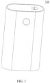
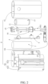
- FIG. 1 and FIG. 2 show an aerosol generation device 100 provided according to an implementation of this application, which includes a housing 6 and an infrared heater.
- the infrared heater is arranged in the housing 6.
- a plurality of infrared electrothermal coatings are disposed on an outer surface of the base body 11 to form a plurality of infrared heating regions.
- the plurality of infrared electrothermal coatings are configured to be dependently started.
- the plurality of infrared electrothermal coatings are connected in a current loop in parallel or series, so that the plurality of infrared electrothermal coatings emit infrared rays to radially heat different portions of an aerosol-forming substrate in a cavity of the base body 11 during the passage of a current.
- Preset pitches are kept between the plurality of infrared electrothermal coatings, so that there are obvious temperature differences between portions of the aerosol-forming substrate corresponding to the infrared electrothermal coatings and portions of the aerosol-forming substrate corresponding to the preset pitches, thereby avoiding the problem of unvarying volatilization of cigarette components and improving the inhalation experience of users.
- the housing 6 includes a shell 61, a fixing shell 62, a base, and a bottom cap 64. Both the fixing shell 62 and the base are fixed in the shell 61.
- the base is configured to fix a base body 11.
- the base is arranged in the fixing shell 62.
- the bottom cap 64 is arranged at one end of the shell 61 and covers the shell 61.
- the base includes a base 15 sleeved at a first end A of the base body 11 and a base 16 sleeved at a second end B of the base body 11.
- the base 15 and the base 16 are arranged in the fixing shell 62.
- An air inlet pipe 641 is arranged protruding from the bottom cap 64.
- An end of the base 16 facing away from the base 15 is connected to the air inlet pipe 641.
- the base 15, the base body 11, the base 16, and the air inlet pipe 641 are coaxially arranged.
- the base body 11 can be sealed with the base 15 and the base 16.
- the base 16 can also be sealed with the air inlet pipe 641.
- the air inlet pipe 641 is in communication with external air to facilitate smooth air intake during inhalation by a user.
- the aerosol generation device 100 further includes a main control circuit board 3 and a battery 7.
- the fixing shell 62 includes a front shell 621 and a rear shell 622.
- the front shell 621 is fixedly connected to the rear shell 622.
- the main control circuit board 3 and the battery 7 are both arranged in the fixing shell 62.
- the battery 7 is electrically connected to the main control circuit board 3.
- a button 4 is arranged protruding from the shell 61.
- An infrared electrothermal coating on a surface of the base body 11 may be energized or de-energized by pressing the button 4.
- the main control circuit board 3 is further connected to a charging interface 31.
- the charging interface 31 is exposed from the bottom cap 64. The user may charge or upgrade the aerosol generation device 100 through the charging interface 31, to ensure continuous use of the aerosol generation device 100.
- the aerosol generation device 100 further includes a heat insulation tube 17.
- the heat insulation tube 17 is arranged in the fixing shell 62.
- the heat insulation tube 17 is arranged in a periphery of the base body 11.
- the heat insulation tube 17 can prevent a large amount of heat from being transferred to the shell 61 to keep the user's hand from a thermal burn.
- the heat insulation tube includes a heat insulation material.
- the heat insulation material may be heat insulation glue, aerogel, aerogel felt, asbestos, aluminum silicate, calcium silicate, diatomite, or zirconium oxide.
- the heat insulation tube 17 may be a vacuum heat insulation tube.
- An infrared ray reflective coating may be further formed in the heat insulation tube 17, to reflect an infrared ray emitted by the infrared electrothermal coating on the base body 11 to the infrared electrothermal coating, thereby improving heating efficiency.
- the aerosol generation device 100 further includes a temperature sensor 2, such as an NTC temperature sensor, configured to detect a real-time temperature of the base body 11 and transmit the detected real-time temperature to the main control circuit board 3.
- the main control circuit board 3 adjusts the magnitude of a current flowing through the infrared electrothermal coating according to the real-time temperature.
- the main control circuit board 3 controls the battery 7 to output a relatively high voltage to a conductive element, to further increase a current fed into the infrared electrothermal coating, thereby increasing a heating power of the aerosol-forming substrate, and reducing a time for the user to wait to inhale the first puff.
- the main control circuit board 3 controls the battery 7 to output a normal voltage to the conductive element.
- the main control circuit board 3 controls the battery 7 to output a relatively low voltage to the conductive element.
- the main control circuit board 3 controls the battery 7 to stop outputting a voltage to the conductive element.
- FIG. 3 is a schematic diagram of another infrared heater according to an implementation of this application.
- the infrared heater includes: a base body 11, configured in a tubular shape extending in an axial direction of a cavity and surrounding the cavity.
- the cavity is configured to receive an aerosol-forming substrate.
- the base body 11 includes a first end (or a near end) A and a second end (or a far end) B and a surface extending between the first end A and the second end B.
- the base body 11 may be in a shape of a cylinder, a prism, or another column, or non-column (for example, plate-shaped).
- the base body 11 is in a shape of a cylinder.
- the cavity is a cylindrical hole running through a middle part of the base body 11. An inner diameter of the hole is slightly greater than an outer diameter of an aerosol-forming product, so that the aerosol-forming product may be placed in the cavity for heating.
- the base body 11 may be made of a high temperature-resistant and transparent material, and may be made of another material with a relatively high infrared transmittance, for example, a high temperature-resistant material with an infrared transmittance above 95%. This is not specifically limited herein.
- the aerosol-forming substrate is a substrate that can release volatile compounds that can form an aerosol.
- the volatile compounds may be released by heating the aerosol-forming substrate.
- the aerosol-forming substrate may be a solid or a liquid or include solid and liquid components.
- the aerosol-forming substrate may be loaded on a carrier or a support through adsorption, coating, impregnation, or another manner.
- the aerosol-forming substrate may conveniently be a part of the aerosol-forming product.
- the aerosol-forming substrate may include nicotine.
- the aerosol-forming substrate may include tobacco, for example, may include a tobacco-containing material including volatile tobacco aroma compounds. The volatile tobacco aroma compounds are released from the aerosol-forming substrate when heated.
- the aerosol-forming substrate may include a homogeneous tobacco material such as leaf tobacco.
- the aerosol-forming substrate may include at least one aerosol-forming agent, and the aerosol-forming agent may be any appropriate known compound or a mixture of compounds. During use, the compound or the mixture of compounds facilitates and stabilizes formation of the aerosol and is substantially resistant to thermal degradation at an operating temperature of an aerosol-forming system.
- the appropriate aerosol-forming agent is well known in the art, and includes, but not limited to: polyol, such as triethylene glycol, 1,3-butanediol, and glycerin; polyol ester, such as monoglyceride and diacetate or triacetate; and monobasic carboxylic acid, dibasic carboxylic acid, and polybasic carboxylic acid fatty acid ester, such as dimethyl dodecane dibasic ester and dimethyl tetradecane dibasic ester.
- the aerosol-forming agent is polyhrdric ester or a mixture thereof, such as triethylene glycol, 1,3-butanediol, or most preferably, glycerol.
- the infrared electrothermal coating 111 is formed on the surface of the base body 11.
- the infrared electrothermal coating 111 may be formed on an outer surface of the base body 11, or may be formed on an inner surface of the base body 11.
- the outer surface of the base body 11 includes three coating regions arranged at intervals in an axial direction of the cavity. Adjacent coating regions are spaced by a non-coating region 112 to keep a preset pitch.
- a first infrared electrothermal coating 1111, a second infrared electrothermal coating 1112, and a third infrared electrothermal coating 1113 are respectively arranged in the three coating regions.
- the first infrared electrothermal coating 1111 and the second infrared electrothermal coating 1112 are spaced by a first non-coating region 1121
- the second infrared electrothermal coating 1112 and the third infrared electrothermal coating 1113 are spaced by a second non-coating region 1122.
- lengths of the first non-coating region 1121 and the second non-coating region 1122 in the axial direction range from 2 mm to 10 mm, preferably 2 mm to 8 mm, further preferably 3 mm to 8 mm, further preferably 4 mm to 8 mm, further preferably 5 mm to 8 mm, and further preferably 5 mm to 7 mm. It should be noted that, the length of the first non-coating region 1121 in the axial direction and the length of the second non-coating region 1122 in the axial direction may be the same or different.
- the lengths of the first infrared electrothermal coating 1111, the second infrared electrothermal coating 1112, and the third infrared electrothermal coating 1113 in the axial direction may be the same or different, and equivalent resistances thereof may be the same or different.
- the lengths of the first infrared electrothermal coating 1111 and the third infrared electrothermal coating 1113 in the axial direction may be set smaller than the length of the second infrared electrothermal coating 1112 in the axial direction, so that the equivalent resistances of the first infrared electrothermal coating 1111 and the third infrared electrothermal coating 1113 are smaller than the equivalent resistance of the second infrared electrothermal coating 1112.
- the infrared electrothermal coating 111 receives an electric power, higher current density and more heat are generated at two ends of the base body 11, and temperature compensation at the two ends of the base body can be implemented.
- a wait time for smoke discharge can be shortened by setting a smaller equivalent resistance of the first infrared electrothermal coating 1111, and the inhalation experience of users can be further improved.
- the infrared electrothermal coating 111 receives the electric power to generate heat, thereby generating an infrared ray of a certain wavelength, for example, a far-infrared ray of 8 ⁇ m to 15 ⁇ m.
- a far-infrared ray 8 ⁇ m to 15 ⁇ m.
- the wavelength of the infrared ray is not limited, which may be an infrared ray of 0.75 ⁇ m to 1000 ⁇ m, preferably a far-infrared ray of 1.5 ⁇ m to 400 ⁇ m.
- the first infrared electrothermal coating 1111, the second infrared electrothermal coating 1112, and the third infrared electrothermal coating 1113 are configured to dependently receive the electric power of a power supply to generate heat and then generate infrared rays, so as to radially heat different parts of the aerosol-forming substrate.
- the infrared electrothermal coating 111 is preferably obtained by fully and uniformly stirring a far-infrared electrothermal ink, ceramic powder, and an inorganic binder, coating the mixture on the outer surface of the base body 11, and then performing drying and curing for a certain time.
- the thickness of the infrared electrothermal coating 111 is 30 ⁇ m to 50 ⁇ m.
- the infrared electrothermal coating 111 may be obtained by mixing and stirring tin tetrachloride, tin oxide, antimony trichloride, titanium tetrachloride, and anhydrous copper sulfate in certain proportions and coating the mixture on the outer surface of the base body 11, or is one of a silicon carbide ceramic layer, a carbon fiber layer, a carbon fiber composite layer, a zirconium titanium oxide ceramic layer, a zirconium titanium nitride ceramic layer, a zirconium titanium boride ceramic layer, a zirconium titanium carbide ceramic layer, an iron oxide ceramic layer, an iron nitride ceramic layer, an iron boride ceramic layer, an iron carbide ceramic layer, a rare earth oxide ceramic layer, a rare earth nitride ceramic layer, a rare earth boride ceramic layer, a rare earth carbide ceramic layer, a nickel cobalt oxide ceramic layer, a nickel cobalt nitride ceramic layer, a nickel cobalt
- the infrared electrothermal coating may be a coating of another material, such as a derivative and compound with carbon as part or all of constituent elements, including but is not limited to, carbon nanotubes, a carbon nanotube film, graphene, carbon fiber, a carbon fiber film, a carbon film, and a carbon fiber sheet.
- the conductive element is configured to supply power dependently to the first infrared electrothermal coating 1111, the second infrared electrothermal coating 1112, and the third infrared electrothermal coating 1113.
- the conductive element includes a first electrode 113 and a second electrode 114 arranged at an interval on the base body 11.
- the first electrode 113 and the second electrode 114 are both conductive coatings.
- the conductive coating may be a metal coating or a conductive tape.
- the metal coating may be made of silver, gold, palladium, platinum, copper, nickel, molybdenum, tungsten, niobium or an alloy of the foregoing metal.
- the first electrode 113 and second electrode 114 are at least partially overlapped with the first infrared electrothermal coating 1111, the second infrared electrothermal coating 1112, and the third infrared electrothermal coating 1113 to form an electrical connection to feed an electrical power to the first infrared electrothermal coating 1111, the second infrared electrothermal coating 1112, and the third infrared electrothermal coating 1113.
- the first electrode 113 includes a coupling portion 1132 and a conductive portion 1131 extending axially from the coupling portion 1132 toward a second end B.
- the coupling portion 1132 extends in a circumferential direction of the base body 11 to form an annular electrode.
- the conductive portion 1131 is at least partially overlapped with the first infrared electrothermal coating 1111, the second infrared electrothermal coating 1112, and the third infrared electrothermal coating 1113 to form an electrical connection.
- the coupling portion 1132 is not overlapped with, that is, is spaced apart from the first infrared electrothermal coating 1111, the second infrared electrothermal coating 1112, and the third infrared electrothermal coating 1113.
- the second electrode 114 includes a coupling portion 1142 and a conductive portion 1141 extending axially from the coupling portion 1142 toward a first end A.
- the coupling portion 1142 extends in the circumferential direction of the base body 11 to form the annular electrode.
- the conductive portion 1141 is at least partially overlapped with the first infrared electrothermal coating 1111, the second infrared electrothermal coating 1112, and the third infrared electrothermal coating 1113 to form an electrical connection.
- the coupling portion 1142 is not overlapped with the first infrared electrothermal coating 1111, the second infrared electrothermal coating 1112, and the third infrared electrothermal coating 1113.
- the coupling portion 1132 and the coupling portion 1142 extending in the circumferential direction of the base body 11 may form an arc-shaped electrode, that is, an electrode in a shape other than a closed ring.
- the coupling portion 1132 and the coupling portion 1142 may be disposed at the same end of the base body 11, for example, immediately adjacent to the second end B.
- the conductive portion 1131 and the conductive portion 1141 are disposed symmetrically along a central axis of the base body 11.
- a current may flow into the conductive portion 1131 and circumferentially flow through the first infrared electrothermal coating 1111, the second infrared electrothermal coating 1112, and the third infrared electrothermal coating 1113 to reach the conductive portion 1141, so that the first infrared electrothermal coating 1111, the second infrared electrothermal coating 1112, and the third infrared electrothermal coating 1113 simultaneously radiate infrared rays to the cavity to heat different portions of the aerosol-forming substrate.
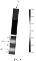
- FIG. 4 is a schematic diagram of the effect of heating a cigarette 20 by the infrared heater shown in FIG. 3 .
- the first infrared electrothermal coating 1111 radially heats a portion A of the cigarette
- the second infrared electrothermal coating 1112 radially heats a portion B of the cigarette
- the third infrared electrothermal coating 1113 radially heats a portion C of the cigarette.
- a portion AB of the cigarette corresponds to the first non-coating region 1121.
- a portion BC of the cigarette corresponds to the second non-coating region 1122.
- the heat for the portion AB and the portion BC of the cigarette mainly comes from thermal conduction of the base body 11 and thermal conduction of adjacent portions.
- the temperature difference may be controlled between 40°C and 80°C. In this example, the temperature difference is controlled at about 60°C.
- a temperature difference between the portion B of the cigarette and the portion AB or the portion BC of the cigarette is similar to the temperature difference between the portion C of the cigarette and the portion BC of the cigarette. The temperature difference can avoid the problem of unvarying volatilization of cigarette components, thereby improving the inhalation experience of users.
- FIG. 5 is a schematic diagram of another infrared heater according to an implementation of this application. Differences from FIG. 3 lie in that an outer surface of the base body 11 includes three coating regions arranged at intervals in a circumferential direction of a cavity. A first infrared electrothermal coating 1111, a second infrared electrothermal coating 1112, and a third infrared electrothermal coating 1113 are respectively arranged in three coating regions. The first infrared electrothermal coating 1111 and the second infrared electrothermal coating 1112 are spaced by the first non-coating region 1121. The second infrared electrothermal coating 1112 and the third infrared electrothermal coating 1113 are spaced by the second non-coating region 1122.
- the third infrared electrothermal coating 1113 and the first infrared electrothermal coating 1111 are spaced by the third non-coating region 1123.
- Each of the first electrode 113 and the second electrode 114 extends in the circumferential direction of the base body 11 to form an annular electrode (or an arc-shaped electrode).
- the first electrode 113 and the second electrode 114 are coupled to the power supply.
- the first electrode 113 is coupled to the positive electrode of the power supply.
- the second electrode 114 is coupled to the negative electrode of the power supply.
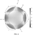
- FIG. 6 is a schematic diagram of the effect of heating a cigarette 20 by the infrared heater shown in FIG. 5 . Similar to the foregoing, there are obvious temperature differences between the portion A of the cigarette and the portion AB or the portion CA of the cigarette, between the portion B of the cigarette and the portion AB or the portion BC of the cigarette, and between the portion C of the cigarette and the portion CA or the portion BC of the cigarette.
- a plurality of infrared heating regions of the infrared heater may be formed by an infrared radiation layer through thermal excitation or by a film configuration that can be wound on the base body 11.
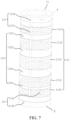
- FIG. 7 is a schematic diagram of still another infrared heater according to an implementation of this application. Differences from FIG. 3 lie in that an outer surface of the base body 11 includes five coating regions arranged at intervals in a circumferential direction of a cavity. A first infrared electrothermal coating 1111, a second infrared electrothermal coating 1112, a third infrared electrothermal coating 1113, a fourth infrared electrothermal coating 1114, and a fifth infrared electrothermal coating 1115 are respectively arranged in the five coating regions and are spaced by a first non-coating region 1121, a second non-coating region 1122, a third non-coating region 1123, and a fourth non-coating region 1124.
- the lengths of the first non-coating region 1121 adjacent to a first end A and the fourth non-coating region 1124 adjacent to a second end B in the axial direction are smaller, while the lengths of the second non-coating region 1122 and the third non-coating region 1123 in the axial direction are larger.
- higher current density and more heat are generated at both ends of the base body 11, and temperature compensation can be implemented at two ends of the base body.
- the lengths of the first infrared electrothermal coating 1111, the second infrared electrothermal coating 1112, the third infrared electrothermal coating 1113, the fourth infrared electrothermal coating 1114, and the fifth infrared electrothermal coating 1115 in the axial direction may be different.
- FIG. 8 is a partially unfolded schematic diagram of still another infrared heater according to an implementation of this application. Differences from FIG. 3 lie in that an outer surface of the base body 11 includes a plurality of coating regions and a plurality of non-coating regions 112. A plurality of infrared electrothermal coatings 111 are disposed in the plurality of coating regions. The plurality of infrared electrothermal coatings 111 and the plurality of non-coating regions 112 form a mesh structure together. The conductive portion 1131 and the conductive portion 1141 are overlapped with a portion of the infrared electrothermal coating 111 to form an electrical connection.
- FIG. 9 is a schematic diagram of still another infrared heater according to an implementation of this application.
- the infrared heater includes an infrared electrothermal coating 211, a first electrode 212, a second electrode 213, and a third electrode 214 that are formed on a base body 21.
- the infrared electrothermal coating 211 is spaced in the axial direction of the outer surface of the base body 21 by a first infrared electrothermal coating 2111 and a second infrared electrothermal coating 2112.
- the first electrode 212 includes a coupling portion 2121 and a conductive portion 2122.
- the second electrode 213 includes a coupling portion 2131 and a conductive portion 2132.
- the third electrode 214 includes a coupling portion 2141 and a conductive portion 2142.
- the first infrared electrothermal coating 2111 and the second infrared electrothermal coating 2112 may be controlled to start independently to implement segmented heating through the arrangement of the first electrode 212, the second electrode 213, and the third electrode 214.
- the first infrared electrothermal coating 2111 and the second infrared electrothermal coating 2112 are equivalent to two independent infrared heaters.
- a plurality of infrared heating regions can be constructed in each part according to a manner in FIG. 3 or FIG. 7 , so that there are obvious temperature differences between portions of the aerosol-forming substrate corresponding to the infrared heating regions and portions of the aerosol-forming substrate corresponding to the preset pitches, thereby avoiding the problem of unvarying volatilization of cigarette components and improving the inhalation experience of users. It is readily conceivable that the same can be achieved for a plurality of independently started infrared electrothermal coatings spaced in the circumferential direction of the outer surface of the base body 21. It should be noted that the structure of the segmented heating is not limited to the case shown in FIG. 9 .
- the aerosol generation device 100 further includes an electrode connector 14.
- the electrode connector 14 is electrically connected to the first electrode 113 and the second electrode 114, and the first electrode 113 and the second electrode 114 respectively extend to positions away from the base body 11.
- the electrode connector 14 electrically connected to the second electrode 114 used as an example for description below:
- the electrode connector 14 includes a contact portion and an extending portion 142. At least a part of the contact portion protrudes toward the outer surface of the base body 11 to contact the coupling portion 1142 to form an electrical connection.
- the extending portion 142 extends toward a position away from the base body 11 relative to the contact portion.
- the extending portion 142 is configured to be coupled to a power supply.
- the contact portion includes a body 141 and four cantilevers 1411 extending from the body 141.
- the four cantilevers 1411 protrude from a surface of one side of the body 141. In this way, when the cantilever 1411 abuts against the coupling portion 1142, an elastic force can be generated to implement the electrical connection with the coupling portion 1142.
- the extending portion 142 extends from the body 141 toward a position away from the base body 11.
- the shape of the body 141 matches the shape of an end portion of the base body 11. Specifically, the body 141 is formed in an arc shape.
- the body 141 has an abutting portion 1412 extending radially.
- the arc-shaped body 141 abuts against an end portion surface of the base body 11.
- the abutting portion 1412 abuts against an end portion of the base body 11 to provide a limiting position for limiting a relative position of the contact portion and the base body 11, so that the cantilever 1411 is located at the coupling portion 1142.
- cantilevers 1411 are arranged at intervals on the body 141 in the circumferential direction of the base body 11. In other examples, a quantity of the cantilevers 1411 is not limited. More or fewer than four cantilevers may be provided. It may be understood that a plurality of cantilevers 1411 are helpful for reliable electrical connection of electrodes but increase processing costs. A flexible selection may be made by those skilled in the art as required.
- the aerosol generation device 100 further includes a base 15 sleeved on a first end A and a base 16 sleeved on a second end B.
- the base 15 and the base 16 are made of an insulating, high temperature-resistant, and thermal insulation material.
- the base 15 and the base 16 may have the same structure.
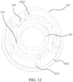
- the base 16 includes an inner cylinder 161 and an outer cylinder 162.
- the base body 11 is detachably sleeved between an outer wall of the inner cylinder 161 and an inner wall of the outer cylinder 162.
- the inner cylinder 161 has a hollow tubular shape. Air flows to the cavity of the base body 11 through the inner cylinder 161.
- a length of the inner cylinder 161 in the axial direction is slightly larger than a length of the coupling portion 1142 in the axial direction.
- a plurality of bosses 1621 distributed in a circumferential direction and extending toward a heat insulation tube 17 are provided on an outer wall of the outer cylinder 162.
- An end portion of the outer cylinder 162 includes an abutting portion 1622 extending in a radial direction.
- the bosses 1621 and an abutting portion 1622 are arranged, so that the end portion of the heat insulation tube 17 can abut against the abutting portion 1622, and a certain gap is provided between an inner wall of the heat insulation tube 17 and the outer wall of the outer cylinder 162 to facilitate the inflow of cool air.
- a plurality of holding portions 1623 distributed at intervals are further provided on the inner wall of the outer cylinder 162. The plurality of holding portions 1623 extend from the inner wall of the outer cylinder 162 to toward the inner cylinder 161. When the base body 11 is sleeved on the base 16, the holding portions 1623 abut against an outer surface of the base body 11 to hold the end portion of the base body 11.
- the base 16 is further provided with a circumferential stop portion for preventing the rotation of the base body 11.
- the circumferential stop portion includes a positioning protrusion 163 disposed protruding from a side of the base 16 facing the base body 11.
- a positioning notch corresponding to and matching the positioning protrusion 163 is opened in a tube wall of the base body 11.
- the positioning protrusion 163 matches a buckle corresponding to the positioning notch, so as to prevent the base body 11 from rotating in the circumferential direction relative to the base 16.
- the base 16 is also provided with a through hole 164 for leading out the extending portion 142 of the electrode connector 14.
Landscapes
- Chemical & Material Sciences (AREA)
- Engineering & Computer Science (AREA)
- Ceramic Engineering (AREA)
- Resistance Heating (AREA)
Applications Claiming Priority (2)
| Application Number | Priority Date | Filing Date | Title |
|---|---|---|---|
| CN202010902708.1A CN114098166A (zh) | 2020-09-01 | 2020-09-01 | 气溶胶生成装置以及红外加热器 |
| PCT/CN2021/116030 WO2022048569A1 (zh) | 2020-09-01 | 2021-09-01 | 气溶胶生成装置以及红外加热器 |
Publications (2)
| Publication Number | Publication Date |
|---|---|
| EP4209137A1 true EP4209137A1 (de) | 2023-07-12 |
| EP4209137A4 EP4209137A4 (de) | 2024-02-21 |
Family
ID=80360645
Family Applications (1)
| Application Number | Title | Priority Date | Filing Date |
|---|---|---|---|
| EP21863633.0A Pending EP4209137A4 (de) | 2020-09-01 | 2021-09-01 | Aerosolerzeugungsvorrichtung und infrarotheizer |
Country Status (6)
| Country | Link |
|---|---|
| US (1) | US20230263229A1 (de) |
| EP (1) | EP4209137A4 (de) |
| JP (1) | JP7713007B2 (de) |
| KR (1) | KR20230050400A (de) |
| CN (1) | CN114098166A (de) |
| WO (1) | WO2022048569A1 (de) |
Families Citing this family (25)
| Publication number | Priority date | Publication date | Assignee | Title |
|---|---|---|---|---|
| CN114304749B (zh) * | 2021-12-31 | 2024-08-09 | 深圳麦时科技有限公司 | 加热不燃烧气溶胶形成装置及其加热件 |
| CN217446705U (zh) * | 2022-03-04 | 2022-09-20 | 深圳市合元科技有限公司 | 加热组件以及包括该加热组件的气溶胶生成装置 |
| CN117137197A (zh) * | 2022-05-24 | 2023-12-01 | 深圳市合元科技有限公司 | 气雾生成装置和发热模组 |
| CN117461886A (zh) * | 2022-07-21 | 2024-01-30 | 深圳市合元科技有限公司 | 加热器以及包括该加热器的气溶胶生成装置 |
| CN117617570A (zh) * | 2022-08-12 | 2024-03-01 | 深圳市合元科技有限公司 | 气雾生成装置、用于气雾生成装置的加热器及控制方法 |
| CN117617569A (zh) * | 2022-08-12 | 2024-03-01 | 深圳市合元科技有限公司 | 气雾生成装置、用于气雾生成装置的加热器及控制方法 |
| CN115486573A (zh) * | 2022-09-16 | 2022-12-20 | 深圳麦时科技有限公司 | 加热组件、气溶胶生成装置及气溶胶生成系统 |
| CN115606867A (zh) * | 2022-09-16 | 2023-01-17 | 深圳麦时科技有限公司 | 加热组件及气溶胶生成装置 |
| CN115606866B (zh) * | 2022-09-16 | 2026-01-16 | 深圳麦时科技有限公司 | 加热组件及气溶胶生成装置 |
| CN117770526A (zh) * | 2022-09-22 | 2024-03-29 | 深圳市合元科技有限公司 | 加热组件以及气溶胶生成装置 |
| CN115553503A (zh) * | 2022-09-30 | 2023-01-03 | 浙江中烟工业有限责任公司 | 一种红外加热器、气溶胶形成装置及红外加热器的制备方法 |
| CN117918581A (zh) * | 2022-10-15 | 2024-04-26 | 深圳市合元科技有限公司 | 加热组件及气溶胶生成装置 |
| CN219373827U (zh) * | 2022-11-17 | 2023-07-21 | 思摩尔国际控股有限公司 | 气溶胶产生装置及其发热结构 |
| CN118160984A (zh) * | 2022-12-08 | 2024-06-11 | 深圳市合元科技有限公司 | 加热器及其制作方法、气溶胶生成装置 |
| CN118235894A (zh) * | 2022-12-22 | 2024-06-25 | 思摩尔国际控股有限公司 | 气溶胶产生装置 |
| CN219982157U (zh) * | 2023-05-23 | 2023-11-10 | 深圳市合元科技有限公司 | 气雾生成装置及用于气雾生成装置的加热器 |
| KR20260003025A (ko) * | 2023-07-26 | 2026-01-06 | 제이티 인터내셔널 소시에떼 아노님 | 에어로졸 발생 장치를 위한 가열 조립체 |
| CN119699645B (zh) * | 2023-09-27 | 2025-12-05 | 深圳麦时科技有限公司 | 气溶胶生成制品和气溶胶生成装置 |
| CN120093013A (zh) * | 2023-12-04 | 2025-06-06 | 深圳市合元科技有限公司 | 气溶胶生成系统及气溶胶生成制品 |
| WO2025227396A1 (en) * | 2024-04-30 | 2025-11-06 | Nicoventures Trading Limited | Aerosol generator for an aerosol provision device |
| WO2025227395A1 (en) * | 2024-04-30 | 2025-11-06 | Nicoventures Trading Limited | Aerosol generator for an aerosol provision device |
| WO2025227388A1 (en) * | 2024-04-30 | 2025-11-06 | Nicoventures Trading Limited | Aerosol generator for an aerosol provision device |
| WO2025227389A1 (en) * | 2024-04-30 | 2025-11-06 | Nicoventures Trading Limited | Aerosol generator for an aerosol provision device |
| KR20260014771A (ko) * | 2024-07-24 | 2026-02-02 | 주식회사 케이티앤지 | 에어로졸 생성장치 |
| CN121867474A (zh) * | 2024-10-17 | 2026-04-17 | 深圳市合元科技有限公司 | 发热组件、发热组件的制备方法和气溶胶生成装置 |
Family Cites Families (13)
| Publication number | Priority date | Publication date | Assignee | Title |
|---|---|---|---|---|
| EP2340730A1 (de) | 2009-12-30 | 2011-07-06 | Philip Morris Products S.A. | Geformtes Heizgerät für ein Aerosolerzeugungssystem |
| CN103315406A (zh) * | 2013-07-17 | 2013-09-25 | 中国烟草总公司郑州烟草研究院 | 一种基于远红外加热的非燃烧型烟草抽吸装置 |
| EP4660588A3 (de) * | 2014-03-21 | 2026-03-18 | Nicoventures Trading Limited | Vorrichtung zum erwärmen von rauchbarem material und artikel aus rauchbarem material |
| JP6957511B2 (ja) * | 2016-05-31 | 2021-11-02 | フィリップ・モーリス・プロダクツ・ソシエテ・アノニム | 側面のくぼみを有するエアロゾル発生装置 |
| KR102231228B1 (ko) | 2017-05-26 | 2021-03-24 | 주식회사 케이티앤지 | 궐련 삽입 감지 기능을 갖는 에어로졸 생성 장치 및 방법 |
| KR101927135B1 (ko) | 2017-06-26 | 2018-12-11 | 전자부품연구원 | 전기 가열식 흡연 장치용 히터 및 그의 제조 방법 |
| CN208957006U (zh) * | 2018-07-23 | 2019-06-11 | 纳智源科技(唐山)有限责任公司 | 烟草物料加热装置及电子烟 |
| CN109077358A (zh) * | 2018-09-19 | 2018-12-25 | 深圳市子午线信息科技有限公司 | 基于纳米远红外分段加热装置及电子烟 |
| CN208925253U (zh) * | 2018-09-19 | 2019-06-04 | 深圳市子午线信息科技有限公司 | 基于纳米远红外分段加热装置及电子烟 |
| CN209931486U (zh) * | 2019-02-28 | 2020-01-14 | 深圳市合元科技有限公司 | 低温烘烤烟具 |
| CN110384264A (zh) * | 2019-07-15 | 2019-10-29 | 深圳市合元科技有限公司 | 加热器及低温加热烟具 |
| DE202020104130U1 (de) * | 2020-07-17 | 2020-08-06 | Leister Technologies Ag | Infrarotstrahler, Infrarotheizelement und Infrarot-Durchlauferhitzer |
| CN215347048U (zh) * | 2020-09-01 | 2021-12-31 | 深圳市合元科技有限公司 | 气溶胶生成装置以及红外加热器 |
-
2020
- 2020-09-01 CN CN202010902708.1A patent/CN114098166A/zh active Pending
-
2021
- 2021-09-01 KR KR1020237008312A patent/KR20230050400A/ko active Pending
- 2021-09-01 JP JP2023513845A patent/JP7713007B2/ja active Active
- 2021-09-01 EP EP21863633.0A patent/EP4209137A4/de active Pending
- 2021-09-01 US US18/024,257 patent/US20230263229A1/en active Pending
- 2021-09-01 WO PCT/CN2021/116030 patent/WO2022048569A1/zh not_active Ceased
Also Published As
| Publication number | Publication date |
|---|---|
| WO2022048569A1 (zh) | 2022-03-10 |
| CN114098166A (zh) | 2022-03-01 |
| JP2023539323A (ja) | 2023-09-13 |
| EP4209137A4 (de) | 2024-02-21 |
| US20230263229A1 (en) | 2023-08-24 |
| KR20230050400A (ko) | 2023-04-14 |
| JP7713007B2 (ja) | 2025-07-24 |
Similar Documents
| Publication | Publication Date | Title |
|---|---|---|
| EP4209137A1 (de) | Aerosolerzeugungsvorrichtung und infrarotheizer | |
| US20230284699A1 (en) | Heater and cigarette device with the heater | |
| US20220338541A1 (en) | Heater and smoking device including heater | |
| CN211910527U (zh) | 加热器以及包括该加热器的烟具 | |
| WO2021129679A1 (zh) | 加热器以及包括该加热器的烟具 | |
| EP4241593A1 (de) | Aerosolerzeugungsvorrichtung und steuerungsverfahren dafür | |
| US12610985B2 (en) | Aerosol-generation device | |
| US12262748B2 (en) | Atomizing device and electronic cigarette | |
| EP4190184A1 (de) | Heizer und zigarettenutensil mit heizer | |
| CN215347048U (zh) | 气溶胶生成装置以及红外加热器 | |
| EP4529780A1 (de) | Heizanordnung und aerosolerzeugungsvorrichtung | |
| WO2021104471A1 (zh) | 加热器以及包含该加热器的烟具 | |
| CN219353089U (zh) | 加热器及气溶胶生成装置 | |
| EP4559331A1 (de) | Aerosolerzeugungsvorrichtung und steuerungsverfahren dafür sowie verfahren zur erzeugung von aerosolen | |
| EP4609736A1 (de) | Heizer und aerosolerzeugungsvorrichtung | |
| EP4537679A1 (de) | Heizer und aerosolerzeugungsvorrichtung damit | |
| EP4544937A1 (de) | Heizanordnung und aerosolerzeugungsvorrichtung | |
| EP4613132A1 (de) | Heizer und herstellungsverfahren dafür sowie aerosolerzeugungsvorrichtung | |
| RU2854324C2 (ru) | Устройство для генерации аэрозоля и нагреватель для указанного устройства |
Legal Events
| Date | Code | Title | Description |
|---|---|---|---|
| STAA | Information on the status of an ep patent application or granted ep patent |
Free format text: STATUS: THE INTERNATIONAL PUBLICATION HAS BEEN MADE |
|
| PUAI | Public reference made under article 153(3) epc to a published international application that has entered the european phase |
Free format text: ORIGINAL CODE: 0009012 |
|
| STAA | Information on the status of an ep patent application or granted ep patent |
Free format text: STATUS: REQUEST FOR EXAMINATION WAS MADE |
|
| 17P | Request for examination filed |
Effective date: 20230228 |
|
| AK | Designated contracting states |
Kind code of ref document: A1 Designated state(s): AL AT BE BG CH CY CZ DE DK EE ES FI FR GB GR HR HU IE IS IT LI LT LU LV MC MK MT NL NO PL PT RO RS SE SI SK SM TR |
|
| DAV | Request for validation of the european patent (deleted) | ||
| DAX | Request for extension of the european patent (deleted) | ||
| STAA | Information on the status of an ep patent application or granted ep patent |
Free format text: STATUS: EXAMINATION IS IN PROGRESS |
|
| A4 | Supplementary search report drawn up and despatched |
Effective date: 20240119 |
|
| RIC1 | Information provided on ipc code assigned before grant |
Ipc: H05B 3/46 20060101ALN20240115BHEP Ipc: H05B 3/14 20060101ALN20240115BHEP Ipc: H05B 3/04 20060101ALN20240115BHEP Ipc: H05B 1/02 20060101ALN20240115BHEP Ipc: A24F 40/20 20200101ALN20240115BHEP Ipc: A24F 40/46 20200101AFI20240115BHEP |
|
| 17Q | First examination report despatched |
Effective date: 20240131 |