EP4209177B1 - Système de radiographie numérique tridimensionnelle (dr) portable - Google Patents
Système de radiographie numérique tridimensionnelle (dr) portable Download PDFInfo
- Publication number
- EP4209177B1 EP4209177B1 EP22205803.4A EP22205803A EP4209177B1 EP 4209177 B1 EP4209177 B1 EP 4209177B1 EP 22205803 A EP22205803 A EP 22205803A EP 4209177 B1 EP4209177 B1 EP 4209177B1
- Authority
- EP
- European Patent Office
- Prior art keywords
- support
- pole
- support tube
- mounting
- rotary
- Prior art date
- Legal status (The legal status is an assumption and is not a legal conclusion. Google has not performed a legal analysis and makes no representation as to the accuracy of the status listed.)
- Active
Links
Images







Classifications
-
- F—MECHANICAL ENGINEERING; LIGHTING; HEATING; WEAPONS; BLASTING
- F16—ENGINEERING ELEMENTS AND UNITS; GENERAL MEASURES FOR PRODUCING AND MAINTAINING EFFECTIVE FUNCTIONING OF MACHINES OR INSTALLATIONS; THERMAL INSULATION IN GENERAL
- F16M—FRAMES, CASINGS OR BEDS OF ENGINES, MACHINES OR APPARATUS, NOT SPECIFIC TO ENGINES, MACHINES OR APPARATUS PROVIDED FOR ELSEWHERE; STANDS; SUPPORTS
- F16M11/00—Stands or trestles as supports for apparatus or articles placed thereon ; Stands for scientific apparatus such as gravitational force meters
- F16M11/20—Undercarriages with or without wheels
- F16M11/24—Undercarriages with or without wheels changeable in height or length of legs, also for transport only, e.g. by means of tubes screwed into each other
- F16M11/26—Undercarriages with or without wheels changeable in height or length of legs, also for transport only, e.g. by means of tubes screwed into each other by telescoping, with or without folding
- F16M11/28—Undercarriages for supports with one single telescoping pillar
-
- A—HUMAN NECESSITIES
- A61—MEDICAL OR VETERINARY SCIENCE; HYGIENE
- A61B—DIAGNOSIS; SURGERY; IDENTIFICATION
- A61B6/00—Apparatus or devices for radiation diagnosis; Apparatus or devices for radiation diagnosis combined with radiation therapy equipment
- A61B6/40—Arrangements for generating radiation specially adapted for radiation diagnosis
-
- A—HUMAN NECESSITIES
- A61—MEDICAL OR VETERINARY SCIENCE; HYGIENE
- A61B—DIAGNOSIS; SURGERY; IDENTIFICATION
- A61B6/00—Apparatus or devices for radiation diagnosis; Apparatus or devices for radiation diagnosis combined with radiation therapy equipment
- A61B6/42—Arrangements for detecting radiation specially adapted for radiation diagnosis
- A61B6/4208—Arrangements for detecting radiation specially adapted for radiation diagnosis characterised by using a particular type of detector
-
- A—HUMAN NECESSITIES
- A61—MEDICAL OR VETERINARY SCIENCE; HYGIENE
- A61B—DIAGNOSIS; SURGERY; IDENTIFICATION
- A61B6/00—Apparatus or devices for radiation diagnosis; Apparatus or devices for radiation diagnosis combined with radiation therapy equipment
- A61B6/44—Constructional features of apparatus for radiation diagnosis
-
- A—HUMAN NECESSITIES
- A61—MEDICAL OR VETERINARY SCIENCE; HYGIENE
- A61B—DIAGNOSIS; SURGERY; IDENTIFICATION
- A61B6/00—Apparatus or devices for radiation diagnosis; Apparatus or devices for radiation diagnosis combined with radiation therapy equipment
- A61B6/44—Constructional features of apparatus for radiation diagnosis
- A61B6/4405—Constructional features of apparatus for radiation diagnosis the apparatus being movable or portable, e.g. handheld or mounted on a trolley
-
- A—HUMAN NECESSITIES
- A61—MEDICAL OR VETERINARY SCIENCE; HYGIENE
- A61B—DIAGNOSIS; SURGERY; IDENTIFICATION
- A61B6/00—Apparatus or devices for radiation diagnosis; Apparatus or devices for radiation diagnosis combined with radiation therapy equipment
- A61B6/44—Constructional features of apparatus for radiation diagnosis
- A61B6/4411—Constructional features of apparatus for radiation diagnosis the apparatus being modular
-
- A—HUMAN NECESSITIES
- A61—MEDICAL OR VETERINARY SCIENCE; HYGIENE
- A61B—DIAGNOSIS; SURGERY; IDENTIFICATION
- A61B6/00—Apparatus or devices for radiation diagnosis; Apparatus or devices for radiation diagnosis combined with radiation therapy equipment
- A61B6/44—Constructional features of apparatus for radiation diagnosis
- A61B6/4429—Constructional features of apparatus for radiation diagnosis related to the mounting of source units and detector units
- A61B6/4452—Constructional features of apparatus for radiation diagnosis related to the mounting of source units and detector units the source unit and the detector unit being able to move relative to each other
-
- F—MECHANICAL ENGINEERING; LIGHTING; HEATING; WEAPONS; BLASTING
- F16—ENGINEERING ELEMENTS AND UNITS; GENERAL MEASURES FOR PRODUCING AND MAINTAINING EFFECTIVE FUNCTIONING OF MACHINES OR INSTALLATIONS; THERMAL INSULATION IN GENERAL
- F16H—GEARING
- F16H19/00—Gearings comprising essentially only toothed gears or friction members and not capable of conveying indefinitely-continuing rotary motion
- F16H19/02—Gearings comprising essentially only toothed gears or friction members and not capable of conveying indefinitely-continuing rotary motion for interconverting rotary or oscillating motion and reciprocating motion
- F16H19/04—Gearings comprising essentially only toothed gears or friction members and not capable of conveying indefinitely-continuing rotary motion for interconverting rotary or oscillating motion and reciprocating motion comprising a rack
-
- F—MECHANICAL ENGINEERING; LIGHTING; HEATING; WEAPONS; BLASTING
- F16—ENGINEERING ELEMENTS AND UNITS; GENERAL MEASURES FOR PRODUCING AND MAINTAINING EFFECTIVE FUNCTIONING OF MACHINES OR INSTALLATIONS; THERMAL INSULATION IN GENERAL
- F16H—GEARING
- F16H25/00—Gearings comprising primarily only cams, cam-followers and screw-and-nut mechanisms
- F16H25/08—Gearings comprising primarily only cams, cam-followers and screw-and-nut mechanisms for interconverting rotary motion and reciprocating motion
- F16H25/12—Gearings comprising primarily only cams, cam-followers and screw-and-nut mechanisms for interconverting rotary motion and reciprocating motion with reciprocation along the axis of rotation, e.g. gearings with helical grooves and automatic reversal
-
- F—MECHANICAL ENGINEERING; LIGHTING; HEATING; WEAPONS; BLASTING
- F16—ENGINEERING ELEMENTS AND UNITS; GENERAL MEASURES FOR PRODUCING AND MAINTAINING EFFECTIVE FUNCTIONING OF MACHINES OR INSTALLATIONS; THERMAL INSULATION IN GENERAL
- F16M—FRAMES, CASINGS OR BEDS OF ENGINES, MACHINES OR APPARATUS, NOT SPECIFIC TO ENGINES, MACHINES OR APPARATUS PROVIDED FOR ELSEWHERE; STANDS; SUPPORTS
- F16M11/00—Stands or trestles as supports for apparatus or articles placed thereon ; Stands for scientific apparatus such as gravitational force meters
- F16M11/02—Heads
- F16M11/04—Means for attachment of apparatus; Means allowing adjustment of the apparatus relatively to the stand
-
- F—MECHANICAL ENGINEERING; LIGHTING; HEATING; WEAPONS; BLASTING
- F16—ENGINEERING ELEMENTS AND UNITS; GENERAL MEASURES FOR PRODUCING AND MAINTAINING EFFECTIVE FUNCTIONING OF MACHINES OR INSTALLATIONS; THERMAL INSULATION IN GENERAL
- F16M—FRAMES, CASINGS OR BEDS OF ENGINES, MACHINES OR APPARATUS, NOT SPECIFIC TO ENGINES, MACHINES OR APPARATUS PROVIDED FOR ELSEWHERE; STANDS; SUPPORTS
- F16M11/00—Stands or trestles as supports for apparatus or articles placed thereon ; Stands for scientific apparatus such as gravitational force meters
- F16M11/02—Heads
- F16M11/04—Means for attachment of apparatus; Means allowing adjustment of the apparatus relatively to the stand
- F16M11/06—Means for attachment of apparatus; Means allowing adjustment of the apparatus relatively to the stand allowing pivoting
- F16M11/10—Means for attachment of apparatus; Means allowing adjustment of the apparatus relatively to the stand allowing pivoting around a horizontal axis
-
- F—MECHANICAL ENGINEERING; LIGHTING; HEATING; WEAPONS; BLASTING
- F16—ENGINEERING ELEMENTS AND UNITS; GENERAL MEASURES FOR PRODUCING AND MAINTAINING EFFECTIVE FUNCTIONING OF MACHINES OR INSTALLATIONS; THERMAL INSULATION IN GENERAL
- F16M—FRAMES, CASINGS OR BEDS OF ENGINES, MACHINES OR APPARATUS, NOT SPECIFIC TO ENGINES, MACHINES OR APPARATUS PROVIDED FOR ELSEWHERE; STANDS; SUPPORTS
- F16M11/00—Stands or trestles as supports for apparatus or articles placed thereon ; Stands for scientific apparatus such as gravitational force meters
- F16M11/02—Heads
- F16M11/18—Heads with mechanism for moving the apparatus relatively to the stand
-
- F—MECHANICAL ENGINEERING; LIGHTING; HEATING; WEAPONS; BLASTING
- F16—ENGINEERING ELEMENTS AND UNITS; GENERAL MEASURES FOR PRODUCING AND MAINTAINING EFFECTIVE FUNCTIONING OF MACHINES OR INSTALLATIONS; THERMAL INSULATION IN GENERAL
- F16M—FRAMES, CASINGS OR BEDS OF ENGINES, MACHINES OR APPARATUS, NOT SPECIFIC TO ENGINES, MACHINES OR APPARATUS PROVIDED FOR ELSEWHERE; STANDS; SUPPORTS
- F16M11/00—Stands or trestles as supports for apparatus or articles placed thereon ; Stands for scientific apparatus such as gravitational force meters
- F16M11/20—Undercarriages with or without wheels
- F16M11/24—Undercarriages with or without wheels changeable in height or length of legs, also for transport only, e.g. by means of tubes screwed into each other
- F16M11/26—Undercarriages with or without wheels changeable in height or length of legs, also for transport only, e.g. by means of tubes screwed into each other by telescoping, with or without folding
- F16M11/32—Undercarriages for supports with three or more telescoping legs
-
- F—MECHANICAL ENGINEERING; LIGHTING; HEATING; WEAPONS; BLASTING
- F16—ENGINEERING ELEMENTS AND UNITS; GENERAL MEASURES FOR PRODUCING AND MAINTAINING EFFECTIVE FUNCTIONING OF MACHINES OR INSTALLATIONS; THERMAL INSULATION IN GENERAL
- F16M—FRAMES, CASINGS OR BEDS OF ENGINES, MACHINES OR APPARATUS, NOT SPECIFIC TO ENGINES, MACHINES OR APPARATUS PROVIDED FOR ELSEWHERE; STANDS; SUPPORTS
- F16M11/00—Stands or trestles as supports for apparatus or articles placed thereon ; Stands for scientific apparatus such as gravitational force meters
- F16M11/42—Stands or trestles as supports for apparatus or articles placed thereon ; Stands for scientific apparatus such as gravitational force meters with arrangement for propelling the support stands on wheels
-
- G—PHYSICS
- G01—MEASURING; TESTING
- G01N—INVESTIGATING OR ANALYSING MATERIALS BY DETERMINING THEIR CHEMICAL OR PHYSICAL PROPERTIES
- G01N23/00—Investigating or analysing materials by the use of wave or particle radiation, e.g. X-rays or neutrons, not covered by groups G01N3/00 – G01N17/00, G01N21/00 or G01N22/00
- G01N23/02—Investigating or analysing materials by the use of wave or particle radiation, e.g. X-rays or neutrons, not covered by groups G01N3/00 – G01N17/00, G01N21/00 or G01N22/00 by transmitting the radiation through the material
- G01N23/04—Investigating or analysing materials by the use of wave or particle radiation, e.g. X-rays or neutrons, not covered by groups G01N3/00 – G01N17/00, G01N21/00 or G01N22/00 by transmitting the radiation through the material and forming images of the material
- G01N23/046—Investigating or analysing materials by the use of wave or particle radiation, e.g. X-rays or neutrons, not covered by groups G01N3/00 – G01N17/00, G01N21/00 or G01N22/00 by transmitting the radiation through the material and forming images of the material using tomography, e.g. computed tomography [CT]
-
- G—PHYSICS
- G01—MEASURING; TESTING
- G01V—GEOPHYSICS; GRAVITATIONAL MEASUREMENTS; DETECTING MASSES OR OBJECTS; TAGS
- G01V5/00—Prospecting or detecting by the use of ionising radiation, e.g. of natural or induced radioactivity
- G01V5/20—Detecting prohibited goods, e.g. weapons, explosives, hazardous substances, contraband or smuggled objects
- G01V5/22—Active interrogation, i.e. by irradiating objects or goods using external radiation sources, e.g. using gamma rays or cosmic rays
- G01V5/226—Active interrogation, i.e. by irradiating objects or goods using external radiation sources, e.g. using gamma rays or cosmic rays using tomography
-
- H—ELECTRICITY
- H02—GENERATION; CONVERSION OR DISTRIBUTION OF ELECTRIC POWER
- H02K—DYNAMO-ELECTRIC MACHINES
- H02K7/00—Arrangements for handling mechanical energy structurally associated with dynamo-electric machines, e.g. structural association with mechanical driving motors or auxiliary dynamo-electric machines
- H02K7/10—Structural association with clutches, brakes, gears, pulleys or mechanical starters
- H02K7/116—Structural association with clutches, brakes, gears, pulleys or mechanical starters with gears
- H02K7/1163—Structural association with clutches, brakes, gears, pulleys or mechanical starters with gears where at least two gears have non-parallel axes without having orbital motion
- H02K7/1166—Structural association with clutches, brakes, gears, pulleys or mechanical starters with gears where at least two gears have non-parallel axes without having orbital motion comprising worm and worm-wheel
-
- A—HUMAN NECESSITIES
- A61—MEDICAL OR VETERINARY SCIENCE; HYGIENE
- A61B—DIAGNOSIS; SURGERY; IDENTIFICATION
- A61B2560/00—Constructional details of operational features of apparatus; Accessories for medical measuring apparatus
- A61B2560/04—Constructional details of apparatus
- A61B2560/0431—Portable apparatus, e.g. comprising a handle or case
-
- F—MECHANICAL ENGINEERING; LIGHTING; HEATING; WEAPONS; BLASTING
- F16—ENGINEERING ELEMENTS AND UNITS; GENERAL MEASURES FOR PRODUCING AND MAINTAINING EFFECTIVE FUNCTIONING OF MACHINES OR INSTALLATIONS; THERMAL INSULATION IN GENERAL
- F16M—FRAMES, CASINGS OR BEDS OF ENGINES, MACHINES OR APPARATUS, NOT SPECIFIC TO ENGINES, MACHINES OR APPARATUS PROVIDED FOR ELSEWHERE; STANDS; SUPPORTS
- F16M2200/00—Details of stands or supports
- F16M2200/02—Locking means
- F16M2200/025—Locking means for translational movement
- F16M2200/028—Locking means for translational movement by positive interaction, e.g. male-female connections
-
- F—MECHANICAL ENGINEERING; LIGHTING; HEATING; WEAPONS; BLASTING
- F16—ENGINEERING ELEMENTS AND UNITS; GENERAL MEASURES FOR PRODUCING AND MAINTAINING EFFECTIVE FUNCTIONING OF MACHINES OR INSTALLATIONS; THERMAL INSULATION IN GENERAL
- F16M—FRAMES, CASINGS OR BEDS OF ENGINES, MACHINES OR APPARATUS, NOT SPECIFIC TO ENGINES, MACHINES OR APPARATUS PROVIDED FOR ELSEWHERE; STANDS; SUPPORTS
- F16M2200/00—Details of stands or supports
- F16M2200/08—Foot or support base
-
- G—PHYSICS
- G01—MEASURING; TESTING
- G01T—MEASUREMENT OF NUCLEAR OR X-RADIATION
- G01T7/00—Details of radiation-measuring instruments
Definitions
- the present disclosure relates to the technical field of three-dimensional digital radiography (DR), and in particular to a portable three-dimensional DR system.
- DR three-dimensional digital radiography
- Three-dimensional DR mainly includes an X-ray generator, a flat panel detector and an image process workstation.
- Three-dimensional DR can be applied in the medical field, three-dimensional DR technology can provide reconstruction images or image groups of the scanned patient's tomography.
- the reconstructed image or image group includes all the image information in the three-dimensional space of the scanned area of the patient, the doctor can acquire the patient's tomography, sagittal section, coronal section or information of any point of the three-dimensional space to assist the diagnosis.
- the three-dimensional DR can also be supplied in the archaeology field to provide a three-dimension image of the relic for acquiring a more specific information, thus the three-dimensional DR has a wide range of applications in the field of fluoroscopy, spot film photography and various kinds of angiography.
- the scanned objects are sent to the three-dimensional DR device for a three-dimensional scanning imaging. While some of the relics cannot be moved, so that instead of being sent to the three-dimensional DR device for a three-dimensional scanning imaging, the relics can just be simply captured for observation. Besides, when the doctor goes to the countryside to diagnose and treat patients or goes to the disaster area to support, some patients are in serious condition, and cannot be transferred to the three-dimensional DR device for three-dimensional imaging to observe the condition, which is not convenient for doctors to make timely treatment.
- US2020000426A1 discloses a method for geometric calibration of a radiography apparatus disposing at least one radio-opaque marker in the field of view of the radiography apparatus.
- a series of tomosynthesis projection images of patient anatomy is acquired from the detector with the X-ray source at different positions along a scan path.
- the spatial and angular geometry of the X-ray source and detector are calculated according to the positions of the marker.
- a tomosynthesis image is reconstructed according to the calculated geometry.
- a rendering of the reconstructed image is displayed.
- WO2013074032A1 discloses an apparatus, systems, and methods for producing X-ray images. More particularly, the disclosure relates to a mobile X-ray apparatus for medical examination for fast, easy and safe transportation.
- An apparatus for producing X-ray images is provided, which comprises a digital Radiography (DR) detector, positioned at a first spatial position, an X-ray tube assembly positionable at a second spatial position at a distance relative the first spatial position, at least one sensor for providing the first spatial position and / or the second spatial position, a control unit for receiving the first spatial position and / or the second spatial position from the at least one sensor, and adapted to control the second spatial position or the first spatial position for alignment of the X-ray tube assembly with the DR detector, based on the first and second spatial positions and a drive wheel, a base, optionally an elevating column, and a telescopic arm, which is rotatable into a direction perpendicular to a driving direction of said base; and wherein said apparatus is automatically controllable
- the present disclosure aims to provide a portable three-dimensional DR system.
- the present disclosure provides a portable three-dimensional DR system.
- the portable three-dimensional DR system includes a support mechanism, an X-ray generator, a stand and a flat panel detector
- the support mechanism includes a support tube, a transmission component, a drive component and a support pole slidingly provided in the support tube
- the X-ray generator is detachably provided on the support pole
- the transmission component is used for driving the X-ray generator to move in the direction of closing to or far from the support tube
- the drive component is used for driving the X-ray generator to rotate
- the flat panel detector is provided on the stand, and the stand is placed on a horizontal plane.
- the transmission component includes: a transmission motor provided in the support pole; a transmission gear; and a transmission rack provided on an inner wall of support tube, and the transmission motor is connected with the transmission gear, the transmission rack is provided in a length direction of the support tube, the transmission gear is engaged with the transmission rack to drive the support pole to slide in the support tube, and one end of the support pole far from the support tube is connected with a mounting platform for mounting the X-ray generator, and the mounting platform is detachably connected with the support tube.
- the support tube includes a first support tube and a second support tube, the first support pole is slidingly provided in the second support tube, the support pole is a telescopic pole and is slidingly provided in the first support tube, the transmission rack comprises a first rack provided on an inner wall of the first support tube and a second rack provided on an inner wall of the second support tube, and the first rack and the second rack are spliced with each other.
- the portable three-dimensional DR system when using the portable three-dimensional DR system, firstly the support pole is pulled out from the support tube, then the X-ray generator is connected to the support pole, and then the stand is placed on the horizontal plane, the flat panel detector is connected to the stand, the scanned object is placed on the side of the flat panel detector, then the transmission component is started to drive the X-ray generator to rotate, so that the object is scanned and photographed, when after used, firstly the X-ray generator is detached from the support pole and the support pole is telescoped into the support tube to be stored, which is convenient to be taken away and the portability of the three-dimensional DR system is improved.
- the transmission motor when using the portable three-dimensional DR system, the transmission motor is started, the transmission rack is driven through the transmission motor to rotate, the transmission gear is engaged with the transmission rack, and the transmission gear can be moved on the transmission rack, so that the support pole can be moved along the arranging direction of transmission rack to drive the X-ray generator to move, besides, when after used, the X-ray generator is detached from the mounting platform, then the support pole is telescoped in the support tube, the mounting platform can be connected with the support tube to protect the support tube, and to avoid the object falling into the support tube, which improves the safety.
- the first support tube when storing the portable three-dimensional DR system, is slidingly provided in the second support tube, then the support pole is telescoped in the first support tube, so that the support tube can be stored for several times, which improves the space utilization.
- a sliding slot is provided on the first support tube, a magnetic plate is provided on the first support tube, the second rack is provided in the sliding slot and magnetically connected with the magnetic plate; and an outer wall of the first support tube is provided with a plurality of position balls, an inner wall of the second support tube is provided with a position hole for containing the position ball and a position slot, the position ball is provided in the position slot and slidingly connected with the second support tube.
- the first support tube is pulled out and then rotated, the position ball is placed in the position hole, the first rack is spliced with the second rack, when storing the portable three-dimensional DR system, firstly the first rack is rotated, then the position ball is placed in the position slot, then the first support tube is telescoped into the second support tube, the second rack is magnetically connected with the magnetic beam by bring provided in the sliding slot, the provision of the position ball plays a role in positioning and fixing, so that the first rack and the second rack is spliced more accurate and more stable.
- a mounting box is detachably connected on the mounting platform, and a containing slot is provided on the mounting box, and a mounting cover for opening or closing the containing slot is further provided on the mounting box, and the X-ray generator is provided in the containing slot and rotatably connected with the mounting box
- the drive component includes:a rotary wheel; and a drive motor provided on the mounting box for driving the rotary wheel to rotate; and the rotary wheel is configured to drive the X-ray generator to rotate.
- the drive motor when using the portable three-dimensional DR system, the drive motor is driven, the drive motor will drive the rotary wheels on two sides of the X-ray generator to rotate the X-ray generator, simultaneous driving of the two sides improves the rotation stability of the X-ray generator, besides, the X-ray generator is provided in the mounting box, when after used, the X-ray generator is rotated to be placed in the containing slot, then the mounting cover is closed to cover the containing slot, the X-ray generator is placed in the mounting box, which reduces the crash of the X-ray generator during transportation.
- an inner wall of the support tube is rotatably provided with a rotary panel, and a rotary hole is provided on the rotary panel, one end of the support pole is rotatably connected with an adjusting pole, and the adjusting pole is threadedly connected with the rotary panel through a rotary hole
- the transmission component includes: a transmission motor provided on the support tube, and an output shaft of the transmission motor is concentrically connected with a first bevel gear, the rotary panel is connected with a second bevel gear, and the first bevel gear is engaged with the second bevel gear.
- the worker can remotely control the transmission motor to rotate, the transmission motor drives the first bevel gear to rotate, the first bevel gear is engaged with the second bevel gear, the second bevel gear is rotated to drive the rotary panel to rotate, then the rotary panel is rotated so that the adjusting pole can drive the support pole to move in the support tube, which improves a space utilization.
- the support tube is further provided with a support component
- the support component includes a support body, a first roller, a connecting plate and a support bar
- the support body is connected with an end of the support pole
- the first roller is rotatably connected with the support body
- the support beam is connected with the support body
- an end of the support bar is rotatably connected with the connecting plate
- another end of the support bar is rotatably connected with a second roller
- a locking piece for locking up the second roller is provided on the support bar.
- the connecting plate is connected to the support body, the support bar is hinged with the support body, when the position of the three-dimensional DR system needs to be adjusted, the support tube can directly be pushed, the whole three-dimensional DR system can be moved under the effect of the first roller and the second roller, then the second roller is locked through the locking piece, so that the three-dimensional DR system is convenient to be moved, besides, when the three-dimensional DR system is used, the support bar can be waved in the direction of closing to the support tube, which is convenient to store the three-dimensional DR system, so that the three-dimensional DR system is portable.
- the stand includes a stand body, a plurality of telescopic feet and an adjusting component, one end of the telescopic foot is hinged with the stand body, and another end of the telescopic foot is placed on a horizontal plane
- the adjusting component includes a moving pole, a rotary pole and a rotary gear
- the rotary pole is rotatably connected with the stand body, one end of the rotary pole is connected with the rotary gear, and a moving rack is provided on the moving pole, the rotary gear is engaged with the moving rack, and an adjusting hole is provided on the stand body, one end of the moving pole is slidingly connected with the stand body through the adjusting hole, and both ends of the moving pole are provided with baffles being parallel to each other, and one of the baffles is slidingly connected with the moving pole, and the baffle is used for clamping the flat panel detector.
- the telescopic foot when using the portable three-dimensional DR system, firstly the telescopic foot is extended and placed on the horizontal plane to support the stand body, then the flat panel detector is placed between the two baffles so that the baffle is convenient to fix the flat panel detector, when the height of the flat panel detector needs to be adjusted, the rotary pole can be rotated to rotate the rotary gear, and the moving pole is driven to slide on the stand body to adjust the height of the flat panel detector, and the scope of application is improved, besides, the telescopic foot can be telescoped, which is convenient to be stored.
- the stand includes a mounting tube, a mounting pole, a mounting panel and a plurality of support-protection bars, the mounting pole is slidingly provided in the mounting tube, a fixing ring is slidingly provided on the mounting pole, and the flat panel detector is detachably connected with the fixing ring, one end of the mounting tube far from the flat panel detector is connected with the mounting panel, the mounting panel is rotatably connected with an end of the support-protection bar, and another end of the support-protection bar is rotatably connected with a caster.
- the flat panel detector when after use, the flat panel detector is detached from the fixing ring for a separate storage, then the mounting pole is telescoped in the mounting tube, and the support-protection bar is rotated in a direction close to the mounting tube for facilitating the three-dimensional system to be stored after use, so as to facilitate the carriage of the three-dimensional DR system.
- the present disclosure includes at least one of the following beneficial technical effects:
- the embodiments of the present disclosure provide a portable three-dimensional DR system.
- the portable three-dimensional DR system includes a support mechanism 1, an X-ray generator 2, a stand 3 and a flat panel detector 4.
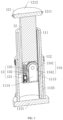
- the support mechanism 1 includes a support pole 12 and a support tube 11, and the support pole 12 is slidingly provided in the support tube 11, sliding in a length direction of the support tube 11.
- the X-ray generator 2 is provided on the support pole 12, the stand 3 is placed on a horizontal plane, and the flat panel detector 4 is provided on the stand 3.
- the support mechanism further includes a transmission component 13 and a drive component 14, the transmission component 13 is used for driving the X-ray generator 2 to move towards or away from the support tube 11, the drive component 14 is used for driving the X-ray generator 2 to rotate, which is convenient to scan and photograph the object.
- the support tube 11 includes a first support tube 111 and a second support tube 112, and both the first support tube 111 and the second support tube 112 of this embodiment are circular structure.
- the outer diameter of the first support tube 111 is smaller than the inner diameter of the second support tube 112, and the first support tube 111 is slidingly provided in the second support tube 112.
- the support pole 12 of this embodiment is a telescopic pole, and one end of the support pole 12 is slidingly provided in the first support tube 111, and another end of the support pole 12 is connected with a mounting platform 121 through a screw, a side of the mounting platform 121 far from the support pole 12 is detachably connected with the X-ray generator.
- a plurality of protrusions 1211 are integrally formed on a sidewall of the mounting platform 121, the quantity of the protrusion 1211 in this embodiment is two, and the two protrusions are oppositely arranged on the two sides of the mounting platform 121.
- An outer wall of the second support tube 112 close to the mounting platform 121 is provided with a fastening component 114, the fastening component 114 includes a fastening bar 1142 and a fastening ring 1141, the fastening bar 1142 is connected with the second support tube 112 through a screw, and the fastening ring 1141 is hinged with the fastening bar 1142.
- a limiting slot is provided on the protrusion 1211, the fastening ring 1141 is provided in the limiting slot and fastened with the protrusion 1211
- the fastening component 114 is used for fixing the mounting platform 121 on the second support tube 112.
- the transmission component 13 includes a transmission rack 134
- the transmission rack 134 includes a first rack 1341 and a second rack 1342
- the first rack 1341 is provided in the first support tube 111, this embodiment is in a screw connection.
- a side of the second rack 1342 is connected with a connecting rack 1123
- a side of the connecting rack 1123 far from the second rack 1342 is connected with an inner wall of the second support tube 112, this embodiment is in a screw connection.
- the first rack 1341 and the second rack 1342 are provided in a same direction with the sliding direction of the support pole 12, and the first rack 1341 and the second rack 1342 are joined together on the side adjacent to each other.
- a sliding slot 1111 is provided on the first support tube 111
- a magnetic plate 1112 is integrally formed on the first support tube 111
- the second rack 1342 is provided in the sliding slot 1111 and magnetically connected with the magnetic plate 1112.
- a plurality of position balls 1113 are integrally formed on an outer wall of the first support tube 111, and the position ball 1113 is sequentially provided along the length direction of the first support tube 111.
- the inner wall of the second support tube 112 is further provided with a position slot 1122 and a position hole 1121 corresponding to the position 1113.
- the position ball 1113 is in the position slot 1122, then the first support tube 111 is pulled out from the second support tube 112, and then the first support tube 111 is rotated to place the position ball 1113 in the position hole, then the first rack 1341 is spliced with the second rack 1342.
- the first support tube 111 When storing the portable three-dimensional DR system, the first support tube 111 is rotated again to place the position ball 1113 in the position slot 1122, so that the first support tube 111 is pushed into the second support tube for a storage, at the moment, the second rack 1342 is in the sliding slot 1111 and magnetically connected with the magnetic plate 1112, the provision of the position ball 1113 is effective on positioning and fixing so that the first rack 1341 and the second rack 1342 are spliced more accurate and stable.
- the transmission component 13 further includes a transmission motor 131, a worm 132 and a transmission gear 133, the transmission gear 133 of this embodiment is a worm gear.
- the transmission motor 131 is provided in the support pole 12, this embodiment is in a screw connection, the transmission motor 131 is connected with the worm 132, and the worm 132 is provided in the length direction of the support pole 12.
- the transmission gear 133 is rotatably provided in the support pole 12 through a mounting frame 1114, and the mounting frame 1114 is connected with the support pole 12 through a screw.
- An abdication slot 1115 is further provided on the support pole 12, a side of the transmission gear 133 is engaged with a worm gear, and another side of the transmission gear 133 is engaged with the rack through the abdication slot 1115.
- the support component 115 includes a support body 1151, a roll bar 11511 and a first roller 1152.
- the support component 115 includes two first rollers 1152. An end of the roll bar 11511 is connected with the first roller 1152 through the screw, another end of the roll bar 11511 passes through the support body 1151 and is connected with another first roller 1152 through the screw.
- the support component 115 further includes a connecting plate 1153 and a support bar 1154, an end of the connecting plate 1153 is connected with the support body 1151 through the screw, another end of the connecting plate 1153 is hinged with an end of the support bar 1154, and another end of the support bar 1154 is rotatably connected with a second roller 11541, the support bar 1154 can be rotated in a direction of closing to the second support tube 112, so that the support bar 1154 is easy to be folded and stored.
- the support bar 1154 is further provided with a locking piece for locking up the second roller 11541, and the quantity of the connecting panel 1153 is two.
- a side of the mounting platform 121 far from the support pole 12 is detachably connected with a mounting box 5, and a side of the mounting box 5 towards the mounting platform 121 is provided with a plurality of through holes 54, the quantity of the through holes 54 are three, and the through holes 54 are evenly distributed on the mounting box 5.
- the inside of the through hole 54 is further slidingly provided with a locking pin 55, the mounting box 5 is hinged with a cover 56 for opening or closing the through hole 54, and an end of the locking pin 55 is attached with the cover 56.
- a side of the mounting platform 121 far from the support pole 12 is correspondingly provided with a lock hole 1212, the mounting box 5 is detachably connected with the mounting platform 121 through the locking pin 55 being slidingly provided in the lock hole 1212.
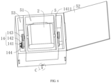
- a containing slot 51 is further provided on the mounting box 5, and the mounting box 5 is further hinged with a mounting cover 52 for opening or closing the containing slot 51.
- the X-ray generator 2 is provided in the containing slot and rotatably connected with the mounting box 5.
- the sidewall of the mounting box 5 is further provided with an interlayer 53, the drive component 14 includes a drive motor 141 and a rotary wheel 143, the drive motor 141 is provided in the interlayer 53 and connected with the mounting box 5, this embodiment is in a screw connection.
- Both two sides of the X-ray generator are passed through the sidewall of the containing slot 51 through a connecting pole to be connected with the rotary wheel 143, the rotary wheel 143 is rotatably connected with the sidewall of the containing slot 51.
- the drive motor 141 is connected with a drive pole 1411, the drive pole 1411 is connected with two driving wheels 142 through the screw, and an end of the driving pole 1411 far from the drive motor 141 is rotatably connected with a sidewall of the interlayer 53.
- One of the driving wheel 142 is rotatably connected with one of the rotary wheel 143 through a belt 144, another driving wheel 142 is rotatably connected with another rotary wheel 143 through the belt 144, when the drive motor 141 starts, the two rotary wheels 143 are driven to rotate simultaneously, so that two sides of the X-ray generator 2 is driven to rotate in the mounting box 5, which improves the space utilization and the rotation stability of the X-ray generator 2, and the drive component 14 is provided in the interlayer 53 of the mounting box 5, so that the portable three-dimensional DR system is more convenient to use.
- the mounting cover 52 can close the containing slot 51, which plays a role in protecting the X-ray generator 2, when get crashed, the damage to the X-ray generator is lowered.
- the stand 3 includes a mounting tube 31 and a mounting pole 32, and the mounting pole 32 is slidingly provided in the mounting tube 31, so that the mounting pole 32 is convenient to be stored in the mounting tube 31.
- An end of the mounting pole 32 far from the mounting tube 31 is provided with a fixing ring 321, and the fixing ring 321 can be slid on the mounting pole 32, and the fixing ring 321 is further provided with a locking screw for locking the sliding distance of the fixing ring 321.
- the fixing ring 321 is connected with a placing panel 322, when after use, the placing panel 322 can be detached from the fixing ring 321 by rotating the screw, which is portable.
- An end of the mounting tube 31 far from the mounting pole 32 is connected with a mounting panel 33 through the screw, the mounting panel 33 of this embodiment is circular.
- a plurality of support-protection bars 34 are rotatably connected in a circumferential direction of the mounting panel 33, the quantity of the support-protection bar of this embodiment is six, and the plurality of support-protection bars 34 are evenly distributed in the circumferential direction of the mounting panel 33 and can be rotated in the direction of closing to the mounting tube 31.
- An end of the support-protection pole 34 far from the mounting panel 33 is further rotatably connected with a caster 341, which is convenient to adjust a direction of the stand 3.
- the implementation principle of embodiment 1 is: when using the portable three-dimensional DR system, the fastening ring 1141 is opened, and the mounting platform 121 is held and pulled up to extend the support pole 12, the first support tube 111 is pulled up, and the first support tube 111 is rotated to place the position ball 1113 in the position hole 1121, then the first rack 1341 and the second rack 1342 are spliced; then the cover 56 of the mounting box 5 is opened to place the locking pin 55 in the locking hole 1212, the mounting box 5 is connected to the mounting platform 121 and the mounting cover 52 is opened, then the position of the X-ray generator is adjusted, so that the object or the human body is convenient to be scanned and photographed.
- the support-protection pole 34 of the mounting tube 31 is rotated to land the caster 341, then the mounting pole 32 is pulled out from the mounting tube 31, the placing panel 322 is fixed on the fixing ring 321, the position of fixing ring 321 on the mounting pole 32 is adjusted to improve the scope of application, then the flat panel detector 4 is placed on the placing 322.
- the transmission motor 131 is controlled through a computer to rotate by a worker so that the transmission gear 133 is rotated, the transmission gear 133 is engaged with the transmission rack 134, the support pole 12 can be moved repeatedly in the length direction of the transmission rack 134, at the same time, the X-ray generator 2 can be driven by the support pole 12 to move repeatedly in the direction of closing to the first support tube 111 or far from the first support tube 111, meanwhile, the drive motor 141 is started, the rotary wheels 143 on the two sides of the X-ray generator 2 are driven by the drive motor 141, so that the two sides of the X-ray generator 2 can be driven to rotate simultaneously, then the human body or the object is convenient to be scanned and photographed.
- the difference between the embodiment 1 and embodiment 2 is that the support tube 11 and the support pole 12 of this embodiment are square structure, and an end of the support pole 12 far from the support tube 11 is connected with the mounting platform 121 through the screw, and the mounting platform 121 of this embodiment is square. As shown in FIG. 8 and FIG.
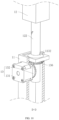
- the inner wall of the support tube 11 is connected with a support panel 113, and the support panel 113 is provided with the mounting hole 1131, the support panel 113 is further provided with a rotary panel 1132, the rotary panel 1132 of this embodiment is circular structure, the mounting panel 33 is rotatably connected with the support panel 113 by being provided in the support hole 1131, and the center of the mounting panel 33 is further provided with a rotary hole 11321.
- the end of the support pole 12 closing to the rotary panel 1132 is connected with an adjusting pole 122 through the screw, the adjusting pole 122 is provided with thread, and an end of the adjusting pole 122 far from the support pole 12 is threadedly connected with the rotary panel 1132 by passing through the rotary hole 11321.
- the transmission component 13 includes a transmission motor 131, a first bevel gear 135 and a second bevel gear 136, the transmission motor 131 is connected to the outer wall of the support tube 11 through the screw, and an output shaft of the transmission motor 131 is passed through the outer wall of the support tube 11 to be coaxially connected with the first bevel gear 135, this embodiment is in the screw connection.
- the second bevel gear 136 is connected to an end of the rotary panel 1132 far from the support pole 12 through the screw, an axis of the second bevel gear 136 is coincided with an axis of the adjusting pole 122, and the first bevel gear 135 is engaged with the second bevel gear.
- the implementation principle of the embodiment 2 is: when using the portable three-dimensional DR system, the support tube 11 is put on the horizontal plane, and the cover 56 of the mounting box 5 is opened to place the locking pin 55 in the locking hole 1212, the mounting box 5 is connected to the mounting platform 121, and then the mounting cover 52 is opened to adjust the position of the X-ray generator, so that the human body or the object is convenient to be scanned and photographed.
- the support-protection pole 34 is possibly to be rotated to land the caster 341, then the mounting pole 32 is pulled out from the mounting tube 31 and the placing panel 322 is fixed on the fixing ring 321, the position of the fixing ring 321 on the mounting pole 32 is adjusted to improve the scope of application and then the flat panel detector 4 is placed on the placing panel 322.
- the transmission motor 131 is controlled through the computer to drive the first bevel gear 135 to rotate by the worker, the first bevel gear 135 is engaged with the second bevel gear 136 to rotate the second bevel gear 136 and the rotary panel 1132 is also driven to rotate, the adjusting pole 122 is driven by the rotary panel 1132 to slide on the rotary panel 1132, the X-ray generator 2 is driven to repeatedly move in the direction of closing to or far from the support tube 11 through the adjusting pole 122, at the same time, the drive motor 141 is started, the rotary wheels 143 on the two sides of the X-ray generator 2 are driven by the drive motor 141, so that the two sides of the X-ray generator 2 can be driven to rotate simultaneously, then the human body or the object is convenient to be scanned and photographed.
- the stand 3 includes a stand body 35 and a telescopic foot 36
- the stand body 35 of this embodiment is of a circular structure
- the telescopic foot 36 of this embodiment is of a telescopic structure
- the quantity of the telescopic foot 36 can be plural
- the quantity of the telescopic foot 36 in this embodiment is three.
- An end of the telescopic foot 36 is hinged with the stand body 35, and another end of the telescopic foot 36 is used for being placed on the horizontal plane.
- the stand body 35 is further provided with an adjusting component 37, the adjusting component includes an adjusting bar 372, a moving pole 371 and a rotary pole 373, the adjusting bar 372 is of a hollow structure, and the adjusting bar 372 is connected with an end of the stand body 35 far from the telescopic foot 36.
- the stand body 35 is provided with an adjusting hole, an end of the moving pole 371 is passed through the adjusting bar 372 and the adjusting hole to be slidingly connected with the stand body 35, and the moving pole 371 is provided with a moving rack 3711.
- An end of the rotary pole 373 is passed through a sidewall of the adjusting bar 372 and coaxially connected with a rotary gear 3732, an end of the rotary gear 3732 far from the rotary pole 373 is rotatably connected with the inner wall of the adjusting bar 372, and the rotary gear 3732 is engaged with the moving rack 3711.
- the end of the rotary pole 373 far from the adjusting bar 372 is connected with a handle 3731 for facilitating the worker to hold and to rotate the rotary pole 373.
- the adjusting component 37 further includes a baffle 374, the quantity of the baffle 374 in this embodiment is two, one of the baffles 374 is connected with the moving panel 3712 through the screw, another baffle 374 is slidingly connected with the guide rod 37121 by being passed through by the guide rod 37121, and the baffle 374 is slid in the direction of closing to or far from the another baffle 374.
- the guide rod 37121 is further provided with a fixing panel 3713, this embodiment is in a screw connection.
- the moving panel 3712 is further provided with an adjusting bolt 37122 for adjusting the sliding distance of the baffle 374, and an end of the adjusting bolt 37122 far from a nut is sequentially passed through the moving panel 3712 and the baffle 374, and the adjusting bolt 37122 is rotataly connected with a side of the fixing panel 3713, the baffle 374 is threadedly connected with the adjusting bolt 37122.
- the adjusting bolt 37122 can be rotated to slide the baffle 374 on the guide rod 37121.
- a limiting panel is integrally formed on the baffle 374, the flat panel detector 4 is provided between the two baffles 374 and is attached to the limiting panel 3741.
- the implementation principle of the embodiment 3 when using the portable three-dimensional DR system, the support tube 11 is placed on the horizontal plane, then the cover 56 of the mounting box 5 is opened to place the locking pin 55 in the locking hole 1212, the mounting box 5 is connected to the mounting platform 121, and then the mounting cover 52 is opened to adjust the position of the X-ray generator 2, which is convenient to scan and photograph the human body or the object.
- the length of the telescopic foot 36 is adjusted and the telescopic foot 36 is placed on the horizontal plane, then the adjusting screw is rotated to place the flat panel detector 4 between the two baffle 374, and the adjusting screw is rotated again so that the two baffles 374 are attached with the flat panel detector 4 for fixing the flat panel detector 4. Then the rotary pole 373 is rotated to slide the moving pole 371 on the stand body 35, the height of the flat panel detector 4 is adjusted to improve the scope of application.
- the transmission component 13 is controlled through the computer by the worker to drive the X-ray generator 2 to repeatedly move in the direction of closing to or far from the support tube 11, meanwhile, the X-ray generator 2 is driven by the drive component 14 to rotate, so that the human body or the object is convenient to be scanned and photographed.
Landscapes
- Engineering & Computer Science (AREA)
- Health & Medical Sciences (AREA)
- Life Sciences & Earth Sciences (AREA)
- Medical Informatics (AREA)
- General Engineering & Computer Science (AREA)
- Physics & Mathematics (AREA)
- General Health & Medical Sciences (AREA)
- High Energy & Nuclear Physics (AREA)
- Nuclear Medicine, Radiotherapy & Molecular Imaging (AREA)
- Pathology (AREA)
- Radiology & Medical Imaging (AREA)
- Optics & Photonics (AREA)
- Heart & Thoracic Surgery (AREA)
- Molecular Biology (AREA)
- Surgery (AREA)
- Animal Behavior & Ethology (AREA)
- Biomedical Technology (AREA)
- Public Health (AREA)
- Veterinary Medicine (AREA)
- Biophysics (AREA)
- Mechanical Engineering (AREA)
- General Physics & Mathematics (AREA)
- Pulmonology (AREA)
- Theoretical Computer Science (AREA)
- Chemical & Material Sciences (AREA)
- Analytical Chemistry (AREA)
- Biochemistry (AREA)
- Power Engineering (AREA)
- Immunology (AREA)
- General Life Sciences & Earth Sciences (AREA)
- Geophysics (AREA)
- Apparatus For Radiation Diagnosis (AREA)
Claims (7)
- Système de radiographie numérique (DR) tridimensionnel portable, comprenant :un générateur de rayons X (2) ;un support (3) disposé sur un plan horizontal ;un détecteur à écran plat (4) prévu sur le support (3) ; etun mécanisme de support (1) comprenant :un tube de support (11) ;un composant de transmission (13) pour entraîner le générateur de rayons X (2) à se rapprocher ou à s'éloigner du tube de support (11) ;un composant d'entraînement (14) pour entraîner le générateur de rayons X (2) à tourner ; etun poteau de support (12) prévu de manière coulissante dans le tube de support (11), etdans lequel le générateur de rayons X (2) est prévu de manière amovible sur le poteau de support (12) ;caractérisé en ce que le composant de transmission (13) comprend :un moteur de transmission (131) prévu dans le poteau de support (12) ;un engrenage de transmission (133) ; etune crémaillère de transmission (134) prévue sur une paroi interne du tube de support (11), etdans lequel le moteur de transmission (131) est relié à l'engrenage de transmission (133), la crémaillère de transmission (134) est prévue dans une direction de longueur du tube de support (11), l'engrenage de transmission (133) est engagé avec la crémaillère de transmission (134) pour entraîner le poteau de support (12) à coulisser dans le tube de support (11), une extrémité du poteau de support (12) éloignée du tube de support (11) est reliée à une plate-forme de montage (121) pour monter le générateur de rayons X (2), et la plate-forme de montage (121) est reliée de manière amovible au tube de support (11) ; etle tube de support (11) comprend un premier tube de support (111) et un second tube de support (112), le premier poteau de support (12) est prévu de manière coulissante dans le second tube de support (112), le poteau de support (12) est un poteau télescopique et est prévu de manière coulissante dans le premier tube de support (111), la crémaillère de transmission (134) comprend une première crémaillère (1341) prévue sur une paroi interne du premier tube de support (111) et une seconde crémaillère (1342) prévue sur une paroi interne du second tube de support (112), et la première crémaillère (1341) et la seconde crémaillère (1342) sont épissées l'un avec l'autre.
- Système DR tridimensionnel portable selon la revendication 1, dans lequel :une fente de coulissement (1111) est prévue sur le premier tube de support (111), une plaque magnétique (1112) est prévue sur le premier tube de support (111), la seconde crémaillère (1342) est prévue dans la fente de coulissement (1111) et reliée de manière magnétique à la plaque magnétique (1112) ; etune paroi externe du premier tube de support (111) est pourvue d'une pluralité de billes de positionnement (1113), une paroi interne du second tube de support (112) est pourvue d'un trou de positionnement (1121) pour contenir la bille de positionnement (1113) et une fente de positionnement (1122), la bille de positionnement (1113) est prévue dans la fente de positionnement (1122) et reliée de manière coulissante au second tube de support (112).
- Système DR tridimensionnel portable selon la revendication 1, dans lequel :un boîtier de montage (5) est relié de manière amovible sur la plate-forme de montage (121),une fente de réception (51) est prévue sur le boîtier de montage (5),un couvercle de montage (52) pour ouvrir ou fermer la fente de réception (51) est en outre prévu sur le boîtier de montage (5),le générateur de rayons X (2) est prévu dans la fente de réception (51) et relié de manière rotative au boîtier de montage (5),le composant d'entraînement (14) comprend une roue rotative (143) et un moteur d'entraînement (141) prévu sur le boîtier de montage (5) pour entraîner la roue rotative (143) à tourner, etla roue rotative (143) est configurée pour entraîner le générateur de rayons X (2) à tourner.
- Système DR tridimensionnel portable selon la revendication 1, dans lequel :une paroi interne du tube de support (11) est pourvue de manière rotative d'un panneau rotatif (1132), et un trou rotatif (11321) est prévu sur le panneau rotatif (1132), une extrémité du poteau de support (12) est reliée de manière rotative à un poteau de réglage (122), et le poteau de réglage (122) est relié par filetage au panneau rotatif (1132) à travers un trou rotatif (11321),le composant de transmission (13) comprend un moteur de transmission (131) disposé sur le tube de support (11), etun arbre de sortie du moteur de transmission (131) est relié de manière concentrique à un premier engrenage conique (135), le panneau rotatif (1132) est relié à un second engrenage conique (136) et le premier engrenage conique (135) est engagé avec le second engrenage conique (136).
- Système DR tridimensionnel portable selon la revendication 1, dans lequel :le tube de support (11) est en outre pourvu d'un composant de support (115),le composant de support (115) comprend un corps de support (1151), un premier rouleau (1152), une plaque de liaison (1153) et une barre de support (1154), etle corps de support (1151) est relié à une extrémité du poteau de support (12), le premier rouleau (1152) est relié de manière rotative au corps de support (1151), une poutre de support est reliée au corps de support (1151), une extrémité de la barre de support (1154) est reliée de manière rotative à la plaque de liaison (1153), une autre extrémité de la barre de support (1154) est reliée de manière rotative à un second rouleau (11541), et une pièce de verrouillage (11542) pour verrouiller le deuxième rouleau (11541) est prévue sur la barre de support (1154).
- Système DR tridimensionnel portable selon la revendication 1, dans lequel :le support (3) comprend un corps de support (35), une pluralité de pieds télescopiques (36) et un composant de réglage (37),une extrémité du pied télescopique (36) est articulée avec le corps de support (35), et l'autre extrémité du pied télescopique (36) est disposée sur un plan horizontal,le composant de réglage (37) comprend un poteau mobile (371), un poteau rotatif (373) et un engrenage rotatif (3732),le poteau rotatif (373) est relié de manière rotative au corps de support (35), une extrémité du poteau rotatif (373) est reliée à l'engrenage rotatif (3732), et une crémaillère mobile (3711) est prévue sur le poteau mobile (371), l'engrenage rotatif (3732) est engagé dans la crémaillère mobile (3711), etun trou de réglage est prévu sur le corps de support (35), une extrémité du poteau mobile (371) est reliée de manière coulissante au corps de support (35) à travers le trou de réglage, deux extrémités du poteau mobile (371) sont pourvues de plaques de garde (374) parallèles l'un à l'autre, l'un des plaques de garde (374) est reliée de manière coulissante au poteau mobile (371), et la plaque de garde (374) est utilisée pour serrer le détecteur à écran plat (4).
- Système DR tridimensionnel portable selon la revendication 1, dans lequel :le support (3) comprend un tube de montage (31), un poteau de montage (32), un panneau de montage (33) et une pluralité de barres de protection de support (34), etle poteau de montage (32) est prévu de manière coulissante dans le tube de montage (31), une bague de fixation (321) est prévue de manière coulissante sur le poteau de montage (32), le détecteur à écran plat (4) est relié de manière amovible à la bague de fixation (321), une extrémité du tube de montage (31) éloignée du détecteur à écran plat (4) est reliée au panneau de montage (33), le panneau de montage (33) est relié de manière rotative à une extrémité de la barre de protection de support (34), et l'autre extrémité de la barre de protection de support (34) est reliée de manière rotative à une roulette (341).
Applications Claiming Priority (1)
| Application Number | Priority Date | Filing Date | Title |
|---|---|---|---|
| CN202210007624.0A CN114017636B (zh) | 2022-01-06 | 2022-01-06 | 一种便携式三维dr系统 |
Publications (3)
| Publication Number | Publication Date |
|---|---|
| EP4209177A1 EP4209177A1 (fr) | 2023-07-12 |
| EP4209177C0 EP4209177C0 (fr) | 2025-06-18 |
| EP4209177B1 true EP4209177B1 (fr) | 2025-06-18 |
Family
ID=80069823
Family Applications (1)
| Application Number | Title | Priority Date | Filing Date |
|---|---|---|---|
| EP22205803.4A Active EP4209177B1 (fr) | 2022-01-06 | 2022-11-07 | Système de radiographie numérique tridimensionnelle (dr) portable |
Country Status (3)
| Country | Link |
|---|---|
| US (1) | US12232899B2 (fr) |
| EP (1) | EP4209177B1 (fr) |
| CN (1) | CN114017636B (fr) |
Families Citing this family (2)
| Publication number | Priority date | Publication date | Assignee | Title |
|---|---|---|---|---|
| CN118517615B (zh) * | 2024-06-26 | 2026-03-31 | 上海大学 | 一种dr调节装置 |
| CN120522202A (zh) * | 2025-06-06 | 2025-08-22 | 江苏迪业检测科技有限公司 | 一种基于数字射线cr技术的无损检测系统 |
Family Cites Families (16)
| Publication number | Priority date | Publication date | Assignee | Title |
|---|---|---|---|---|
| JP2012095865A (ja) * | 2010-11-02 | 2012-05-24 | Fujifilm Corp | 放射線撮影装置、放射線撮影システム |
| EP2760341B1 (fr) | 2011-11-15 | 2017-02-01 | Solutions for Tomorrow AB | Appareil de production d'images radiographiques |
| ITMI20120099A1 (it) * | 2012-01-27 | 2013-07-28 | Gotzen S R L De | Apparato e metodo per radiografia digitale |
| WO2016018064A1 (fr) * | 2014-07-30 | 2016-02-04 | Samsung Electronics Co., Ltd. | Appareil à rayons x |
| US20180008216A1 (en) * | 2016-07-07 | 2018-01-11 | Samsung Electronics Co., Ltd. | X-ray detector, and x-ray imaging apparatus having the same |
| FR3073290B1 (fr) * | 2017-11-09 | 2020-02-14 | Commissariat A L'energie Atomique Et Aux Energies Alternatives | Dispositif et procede d'inspection tridimensionnelle d'un objet par rayons x |
| US10743822B2 (en) | 2018-06-29 | 2020-08-18 | Carestream Health, Inc. | Fiducial marker for geometric calibration of bed-side mobile tomosynthesis system |
| US10849579B2 (en) | 2018-11-23 | 2020-12-01 | Turner Imaging Systems, Inc. | Support stand for a portable X-ray imaging device |
| CN209645070U (zh) * | 2019-01-07 | 2019-11-19 | 深圳市宝润科技有限公司 | 便携支架 |
| CN210424372U (zh) * | 2019-09-09 | 2020-04-28 | 熊凤英 | 一种隧道综合监控子站保护装置 |
| CN210742163U (zh) * | 2019-09-16 | 2020-06-12 | 深圳市宝润科技有限公司 | X光机 |
| CN210381073U (zh) * | 2019-10-20 | 2020-04-21 | 青岛智目科技有限公司 | 一种轨道车辆零部件视觉检测用的工业相机 |
| CN111578062A (zh) * | 2020-05-15 | 2020-08-25 | 梧州星河科技有限公司 | 一种可调节式科技技术推广用信息采集装置 |
| CN112261249A (zh) * | 2020-10-13 | 2021-01-22 | 江门市新嘉耀信息科技有限公司 | 一种可多角度调节的监控摄像头及其安装结构 |
| CN214434254U (zh) * | 2020-12-01 | 2021-10-22 | 深圳市宝润科技有限公司 | 摄影架和探测设备 |
| CN214663480U (zh) * | 2021-01-11 | 2021-11-09 | 西安顺升电子科技有限公司 | 一种显示器移动支座及显示器 |
-
2022
- 2022-01-06 CN CN202210007624.0A patent/CN114017636B/zh active Active
- 2022-11-02 US US17/979,242 patent/US12232899B2/en active Active
- 2022-11-07 EP EP22205803.4A patent/EP4209177B1/fr active Active
Also Published As
| Publication number | Publication date |
|---|---|
| US20230210485A1 (en) | 2023-07-06 |
| EP4209177C0 (fr) | 2025-06-18 |
| CN114017636A (zh) | 2022-02-08 |
| US12232899B2 (en) | 2025-02-25 |
| EP4209177A1 (fr) | 2023-07-12 |
| CN114017636B (zh) | 2022-04-26 |
Similar Documents
| Publication | Publication Date | Title |
|---|---|---|
| US9039282B2 (en) | Imaging apparatus comprising a ring-shaped gantry | |
| US11382580B2 (en) | CT imaging systems | |
| US8534915B2 (en) | Imaging apparatus comprising a ring-shaped gantry | |
| US9962132B2 (en) | Multi-directional X-ray imaging system with single support column | |
| EP2217147B1 (fr) | Machine de tomographie par ordinateur (ct) et de tomographie monophotonique d'émission (spect) de médecine nucléaire avec un système de spect et de ct à faisceau conique et panneau plat asymétrique intégré | |
| US9055912B2 (en) | Supporting device and intra-operative imaging device having the supporting device | |
| US5638419A (en) | Spiral-helical scan computed tomography apparatus | |
| JP5372461B2 (ja) | 開放型ガントリを設けた可搬型断層写真法診断システム | |
| US8662750B2 (en) | Medical examination device for CT imaging and for nuclear medical imaging | |
| RU2492811C2 (ru) | Рентгеновский аппарат для томографической реконструкции | |
| EP4209177A1 (fr) | Système de radiographie numérique tridimensionnelle (dr) portable | |
| JPS6123987A (ja) | 断層写真作像装置 | |
| EP3666190B1 (fr) | Appareil d'imagerie médicale | |
| JP2003190137A (ja) | 被検体の断層撮影方法及び装置 | |
| WO1987003795A1 (fr) | Procede et dispositif de radiographie, utilisant un montant de support mobile dans le voisinage d'une table d'examen pour patient | |
| CN212326526U (zh) | 检测介入系统及医疗设备 | |
| EP0451231B1 (fr) | Ensemble de portique et de palette utilise en imagerie nucleaire | |
| JPS6120540Y2 (fr) | ||
| KR101474926B1 (ko) | 엑스선 촬영장치 | |
| JPH06269437A (ja) | ディジタルx線撮影装置 | |
| WO2024119240A1 (fr) | Scanner pour animaux | |
| JPS635688Y2 (fr) | ||
| IT201900002910U1 (it) | Apparato per l’acquisizione di radiografie volumetriche cbct | |
| JPH06327663A (ja) | X線回転撮影装置 |
Legal Events
| Date | Code | Title | Description |
|---|---|---|---|
| PUAI | Public reference made under article 153(3) epc to a published international application that has entered the european phase |
Free format text: ORIGINAL CODE: 0009012 |
|
| STAA | Information on the status of an ep patent application or granted ep patent |
Free format text: STATUS: THE APPLICATION HAS BEEN PUBLISHED |
|
| AK | Designated contracting states |
Kind code of ref document: A1 Designated state(s): AL AT BE BG CH CY CZ DE DK EE ES FI FR GB GR HR HU IE IS IT LI LT LU LV MC ME MK MT NL NO PL PT RO RS SE SI SK SM TR |
|
| STAA | Information on the status of an ep patent application or granted ep patent |
Free format text: STATUS: REQUEST FOR EXAMINATION WAS MADE |
|
| 17P | Request for examination filed |
Effective date: 20240112 |
|
| RBV | Designated contracting states (corrected) |
Designated state(s): AL AT BE BG CH CY CZ DE DK EE ES FI FR GB GR HR HU IE IS IT LI LT LU LV MC ME MK MT NL NO PL PT RO RS SE SI SK SM TR |
|
| GRAP | Despatch of communication of intention to grant a patent |
Free format text: ORIGINAL CODE: EPIDOSNIGR1 |
|
| STAA | Information on the status of an ep patent application or granted ep patent |
Free format text: STATUS: GRANT OF PATENT IS INTENDED |
|
| INTG | Intention to grant announced |
Effective date: 20250122 |
|
| GRAS | Grant fee paid |
Free format text: ORIGINAL CODE: EPIDOSNIGR3 |
|
| GRAA | (expected) grant |
Free format text: ORIGINAL CODE: 0009210 |
|
| STAA | Information on the status of an ep patent application or granted ep patent |
Free format text: STATUS: THE PATENT HAS BEEN GRANTED |
|
| AK | Designated contracting states |
Kind code of ref document: B1 Designated state(s): AL AT BE BG CH CY CZ DE DK EE ES FI FR GB GR HR HU IE IS IT LI LT LU LV MC ME MK MT NL NO PL PT RO RS SE SI SK SM TR |
|
| REG | Reference to a national code |
Ref country code: GB Ref legal event code: FG4D |
|
| REG | Reference to a national code |
Ref country code: CH Ref legal event code: EP |
|
| REG | Reference to a national code |
Ref country code: DE Ref legal event code: R096 Ref document number: 602022016044 Country of ref document: DE |
|
| REG | Reference to a national code |
Ref country code: CH Ref legal event code: EP |
|
| REG | Reference to a national code |
Ref country code: IE Ref legal event code: FG4D |
|
| U01 | Request for unitary effect filed |
Effective date: 20250630 |
|
| U07 | Unitary effect registered |
Designated state(s): AT BE BG DE DK EE FI FR IT LT LU LV MT NL PT RO SE SI Effective date: 20250707 |
|
| PG25 | Lapsed in a contracting state [announced via postgrant information from national office to epo] |
Ref country code: NO Free format text: LAPSE BECAUSE OF FAILURE TO SUBMIT A TRANSLATION OF THE DESCRIPTION OR TO PAY THE FEE WITHIN THE PRESCRIBED TIME-LIMIT Effective date: 20250918 Ref country code: GR Free format text: LAPSE BECAUSE OF FAILURE TO SUBMIT A TRANSLATION OF THE DESCRIPTION OR TO PAY THE FEE WITHIN THE PRESCRIBED TIME-LIMIT Effective date: 20250919 |
|
| PG25 | Lapsed in a contracting state [announced via postgrant information from national office to epo] |
Ref country code: HR Free format text: LAPSE BECAUSE OF FAILURE TO SUBMIT A TRANSLATION OF THE DESCRIPTION OR TO PAY THE FEE WITHIN THE PRESCRIBED TIME-LIMIT Effective date: 20250618 |
|
| PG25 | Lapsed in a contracting state [announced via postgrant information from national office to epo] |
Ref country code: RS Free format text: LAPSE BECAUSE OF FAILURE TO SUBMIT A TRANSLATION OF THE DESCRIPTION OR TO PAY THE FEE WITHIN THE PRESCRIBED TIME-LIMIT Effective date: 20250918 |
|
| U20 | Renewal fee for the european patent with unitary effect paid |
Year of fee payment: 4 Effective date: 20250916 |
|
| U1N | Appointed representative for the unitary patent procedure changed after the registration of the unitary effect |
Representative=s name: MURGITROYD & COMPANY; GB |
|
| PG25 | Lapsed in a contracting state [announced via postgrant information from national office to epo] |
Ref country code: IS Free format text: LAPSE BECAUSE OF FAILURE TO SUBMIT A TRANSLATION OF THE DESCRIPTION OR TO PAY THE FEE WITHIN THE PRESCRIBED TIME-LIMIT Effective date: 20251018 |
|
| PG25 | Lapsed in a contracting state [announced via postgrant information from national office to epo] |
Ref country code: SM Free format text: LAPSE BECAUSE OF FAILURE TO SUBMIT A TRANSLATION OF THE DESCRIPTION OR TO PAY THE FEE WITHIN THE PRESCRIBED TIME-LIMIT Effective date: 20250618 |
|
| PG25 | Lapsed in a contracting state [announced via postgrant information from national office to epo] |
Ref country code: CZ Free format text: LAPSE BECAUSE OF FAILURE TO SUBMIT A TRANSLATION OF THE DESCRIPTION OR TO PAY THE FEE WITHIN THE PRESCRIBED TIME-LIMIT Effective date: 20250618 |
|
| PG25 | Lapsed in a contracting state [announced via postgrant information from national office to epo] |
Ref country code: PL Free format text: LAPSE BECAUSE OF FAILURE TO SUBMIT A TRANSLATION OF THE DESCRIPTION OR TO PAY THE FEE WITHIN THE PRESCRIBED TIME-LIMIT Effective date: 20250618 |
|
| PG25 | Lapsed in a contracting state [announced via postgrant information from national office to epo] |
Ref country code: SK Free format text: LAPSE BECAUSE OF FAILURE TO SUBMIT A TRANSLATION OF THE DESCRIPTION OR TO PAY THE FEE WITHIN THE PRESCRIBED TIME-LIMIT Effective date: 20250618 |
|
| PG25 | Lapsed in a contracting state [announced via postgrant information from national office to epo] |
Ref country code: ES Free format text: LAPSE BECAUSE OF FAILURE TO SUBMIT A TRANSLATION OF THE DESCRIPTION OR TO PAY THE FEE WITHIN THE PRESCRIBED TIME-LIMIT Effective date: 20250618 |
|
| PLBE | No opposition filed within time limit |
Free format text: ORIGINAL CODE: 0009261 |
|
| STAA | Information on the status of an ep patent application or granted ep patent |
Free format text: STATUS: NO OPPOSITION FILED WITHIN TIME LIMIT |
|
| REG | Reference to a national code |
Ref country code: CH Ref legal event code: L10 Free format text: ST27 STATUS EVENT CODE: U-0-0-L10-L00 (AS PROVIDED BY THE NATIONAL OFFICE) Effective date: 20260430 |