EP4209310B1 - Dispositif d'aide amovible à raccordement réglable du corps inférieur - Google Patents
Dispositif d'aide amovible à raccordement réglable du corps inférieur Download PDFInfo
- Publication number
- EP4209310B1 EP4209310B1 EP22176855.9A EP22176855A EP4209310B1 EP 4209310 B1 EP4209310 B1 EP 4209310B1 EP 22176855 A EP22176855 A EP 22176855A EP 4209310 B1 EP4209310 B1 EP 4209310B1
- Authority
- EP
- European Patent Office
- Prior art keywords
- support
- operator
- body attachment
- connecting point
- hip
- Prior art date
- Legal status (The legal status is an assumption and is not a legal conclusion. Google has not performed a legal analysis and makes no representation as to the accuracy of the status listed.)
- Active
Links
Images



Classifications
-
- B—PERFORMING OPERATIONS; TRANSPORTING
- B25—HAND TOOLS; PORTABLE POWER-DRIVEN TOOLS; MANIPULATORS
- B25J—MANIPULATORS; CHAMBERS PROVIDED WITH MANIPULATION DEVICES
- B25J9/00—Program-controlled manipulators
- B25J9/0006—Exoskeletons, i.e. resembling a human figure
Definitions
- the invention relates to a towable auxiliary device to assist an operator in lifting and/or holding loads.
- Auxiliary devices can be used to transfer the loads acting on the user when lifting objects either directly into the ground or at least only through selected areas of the body, e.g. a hip area of an operator, and thus relieve the strain on the user's joint and muscle system.
- auxiliary devices As stationary or partially mobile devices, which are installed, for example, at a user's workstation.
- stationary lifting aids such as hose lifters, rope balancers or manipulators are described in the prior art, by means of which piece goods can be picked up and moved from one position to another.
- auxiliary devices are limited in their flexibility, since they cannot simply be moved to a new location and made ready for use there.
- Auxiliary devices are also known which are designed as completely mobile devices that can be put on by the user.
- Such mobile auxiliary devices usually have one or more body connections via which the auxiliary device can be coupled to the body of an operator and via which forces can be transmitted between the auxiliary device and the body.
- exoskeletons are known, which can be used as lifting aids for lifting loads. Designs are known in which the exoskeleton essentially replicates the entire kinematic chain for the lifting process, ie the load-bearing limbs and degrees of freedom of movement of the wearer ("joints" of the exoskeleton) are reproduced as accurately as possible by the exoskeleton. Such solutions are also known as anthropomorphic exoskeletons. However, such exoskeletons have the disadvantage that, due to complexity reasons, As a rule, not all degrees of freedom of the human body are represented, which results in restricted movement and thus reduced user comfort. In addition, such exoskeletons are often heavy and therefore unwieldy.
- Non-anthropomorphic lifting aids which have support elements that can be moved relative to one another and several body attachment points that are rigidly connected to the support elements.
- the known aids can generally only be adapted to a user's specific anatomical conditions to a limited extent, which can have a negative effect on the transfer of force between the body and the aid.
- the known aids often limit the operator's freedom of movement and thus the user's comfort.
- the invention is concerned with the task of providing an auxiliary device which effectively relieves the user when handling an object and which can be flexibly adapted to the anatomical conditions of the user.
- the auxiliary device should allow a high degree of freedom of movement for the user.
- the auxiliary device is designed as a pull-on auxiliary device to assist an operator in lifting and/or holding loads, in the sense of a device that can be worn on a person's body to assist in lifting and/or holding objects ("body-worn lifting aid").
- the auxiliary device is designed in particular in such a way that it can be put on by a person and the person can move to another location with the auxiliary device on.
- the device can be designed in such a way that the operator can put it on like a backpack.
- the auxiliary device comprises a support structure which is designed to absorb a weight force and/or inertia force of a load and to redirect this force to certain body areas of the operator.
- the support structure comprises a first (right) support and a second (left) support separate from the first support.
- the first and second supports each have a back section and a boom section.
- the supports are designed such that when the auxiliary device is put on by the operator, the back section is arranged posteriorly, i.e. dorsally or "at the back" of the body, and extends essentially cranially along the back of the operator starting from the hip or extends cranially along the back of the operator starting from the hip. This does not mean that the Back section must run exactly parallel to the operator's back.
- the boom section is designed in such a way that when the auxiliary device is tightened it extends from posterior to anterior, i.e. ventral or "from the back to the front of the body".
- the back section When the operator is standing upright, the back section extends in particular essentially vertically and the boom section at least partially horizontally.
- the back section can form a vertical support and the boom section can form a horizontal support.
- the back section and/or the boom section can be designed straight along its longitudinal extent or have a curve at least partially along its longitudinal extent.
- the boom section can in particular connect to the back section.
- the respective boom section extends over a shoulder of the operator when the auxiliary device is tightened.
- the back section and the boom section can be designed in one piece or separately from one another.
- the back section can be movably connected to the boom section, for example pivotably about a first and/or second boom pivot axis (see below).
- the back section and the boom section are in particular designed to be dimensionally stable.
- the supports are made of pipe sections and/or cut-to-length profile parts.
- the back section of each support is designed to be adjustable in length.
- the boom section is designed to be adjustable in length.
- the auxiliary device also comprises an upper body connection, in particular an upper body connection, for coupling the support structure to an upper body of the operator.
- an upper body connection in particular an upper body connection, for coupling the support structure to an upper body of the operator.
- the upper body connection can be designed to couple the support structure to a back, shoulder and/or chest area of the operator.
- the auxiliary device also comprises a lower body connection, in particular a hip connection, for coupling the support structure to a pelvic, hip and/or lumbar region of the operator.
- the lower body connection is in particular not designed to couple the support structure to the lower extremities of the operator, such as a thigh, knee or lower leg.
- the upper body connection and the lower body connection are designed in particular in such a way that forces can be transmitted between the body and the support structure.
- the upper body connection can be designed to introduce forces into the body that result from the dead weight of the support structure, support reactions required for static equilibrium and guiding forces of the support sections.
- the lower body connection can be designed in particular to to introduce the forces and/or moments resulting from the handling of a load into the body.
- the upper and/or lower body connection are designed to fix the support structure to a body region of the operator and thus to hold the auxiliary device to the operator's body.
- the upper and/or lower body connection are designed in particular such that the auxiliary device can be "pulled on” by the operator by coupling the support structure to the body using the upper or lower body connection.
- the upper and/or lower body connection can be detachably connected to the support structure, in particular can be repeatedly connected and separated again.
- the upper body connection and the lower body connection are arranged at a distance from one another and, in particular exclusively, force-coupled to one another via the support structure. This has the advantage that no or only a small proportion of the vertical forces resulting directly from a held load are introduced into the user's upper body.
- the auxiliary device also comprises a first (right) hand connection for connection to a right hand or forearm area of the operator, for example to a wrist and/or carpus of the operator.
- the first hand connection is connected to the first support, in particular to a free end of the boom section of the first support, via a first length-adjustable connecting device.
- the auxiliary device also comprises a second (left) hand connection for connection to a left hand or forearm area of the operator, for example a wrist and/or a carpus of the operator.
- the second hand connection is connected to the second support, in particular a free end of the boom section of the second support, via a second length-adjustable connecting device.
- the hand connections serve as a link between the human hand and the auxiliary device.
- the weight and inertia forces of the load held can be introduced into the support structure via the hand connections and the connecting devices and then introduced into selected areas of the operator's body via the body connections.
- the proposed auxiliary device support begins in particular from the operator's wrist.
- the hand connections are preferably designed in such a way that the human hand itself is used to grip the object to be lifted, which is superior to technical gripping systems in terms of its versatility.
- the hand connections can be designed in various ways. For example, a design as a cuff that encloses the carpus and possibly also the wrist of the hand is conceivable.
- the length-adjustable connecting devices can be designed in particular as a cable pull.
- the first hand connection can be connected to the first support via a first cable pull and the second hand connection can be connected to the second support via a second cable pull.
- a common or respective drive device can be provided for driving the cables.
- active support of the operator can be achieved, e.g. during a lifting process or when statically holding a load.
- the at least one drive device can in particular be held on the support structure.
- the cables of the cables can each be guided via a cable guide, preferably running within the respective support, and exit from the support, in particular the boom section, via a cable deflection device.
- the first support in particular the back section of the first support
- the second support in particular the back section of the second support
- the lower body connection is also designed such that a relative position of the first lower connection point and the second lower connection point is changeable, in particular adjustable.
- the lower body connection comprises at least one adjustment mechanism, which is designed to change a relative position of the first lower connection point and the second lower connection point.
- the lower body connection can advantageously be designed in such a way that a distance between the first lower connection point and the second lower connection point can be changed, in particular adjustable.
- the lower body connection can be designed in such a way that a position of the first lower connection point and/or the second lower connection point can be changed laterally and/or medially relative to the median plane, i.e. in particular orthogonally to the median plane, when the auxiliary device is put on by the operator.
- the median plane - as is usual in anatomy - refers to a, in particular vertical, body plane which extends from the front body wall to the back body wall and divides the body symmetrically into a right and a left half.
- the lower body connection is designed in such a way that when the auxiliary device is put on by the operator, a position of the first lower connection point and/or the second lower connection point can be changed, in particular adjusted, in the anterior direction and/or in the posterior direction relative to the frontal plane, in particular orthogonal to the frontal plane.
- This makes it possible to set a dorsal distance of the first and/or second lower connection point to the frontal plane, i.e. in particular a distance of the first and/or second lower connection point to the operator's back, and in this way to adapt the auxiliary device to a specific back shape of the operator.
- the frontal plane refers - as is usual in anatomy - to a body plane, in particular a vertical one, which divides the body into a front and a rear part.
- the first and the second support can each be connected to the lower body connection in an articulated manner.
- Such an articulated connection of the supports to the lower body connection enables a relative movement of the support structure and the lower body connection and thus increases the freedom of movement of the operator when the Auxiliary device.
- the first support preferably the back section of the first support
- the second support preferably the back section of the second support
- the first support and the second support are connected to the lower body connection via a ball joint.
- the lower body connection can comprise a lower force distribution device which is connected to the supports, in particular to the back sections of the supports.
- the lower body connection can comprise a body connection device connected to the lower force distribution device via one or more force introduction points or force introduction surfaces for connection to a body region of the operator, in particular to a hip, pelvic and/or lumbar region of the operator.
- the lower force distribution device is designed in particular to absorb forces from the supports and redirect them to the body connection device, which then introduces the forces into the body of the operator, in particular over a large area and avoiding pressure peaks.
- the lower body connection device is designed to be flexible, so that the body connection device can be variably adapted to the specific anatomical conditions of the operator.
- the lower body connection device can comprise at least one textile part, in particular consist of it.
- the at least one textile part can be designed, for example, in the form of a flexible belt or a cuff.
- the lower body connection device comprises one or more belts which enclose the pelvis and/or the hips of the operator and are equipped with corresponding closing elements.
- Such a design offers a high level of wearing comfort and at the same time promotes reliable mounting of the auxiliary device on the body of the operator, which enables efficient force introduction in the area of the hip.
- the lower force distribution device can have a lower base body on which the supports are arranged, in particular via the lower joint devices.
- the lower base body preferably extends between the first support and the second support, in particular between the back section of the first support and the back section of the second support.
- the base body thus serves as a lower connecting link between the first and the second support.
- the base body can be constructed in one or more parts.
- the lower body connection in particular the lower base body, comprises a first lower adjustment mechanism which is designed to change, in particular to adjust, a distance between the lower connection points.
- the first lower adjustment mechanism can be designed to change a position of the lower connection points laterally and/or medially relative to the median plane when the auxiliary device is tightened.
- the supports are each held on a rack which is held on the base body so that it can be moved laterally and medially via a rack mechanism.
- the lower body connection comprises a second lower adjustment mechanism which is designed to change a position of the lower connection points in the anterior (ventral) direction and in the posterior (dorsal) direction relative to the frontal plane.
- first and second supports in particular the first and second lower joint devices, are each held on the base body so that they can pivot about a pivot axis via a pivot device.
- the pivot axis is oriented orthogonally to the transverse plane when the auxiliary device is tightened and the body is in an upright position.
- the transverse plane refers to a plane - as is usual in anatomy - which is transverse, i.e.
- the pivoting device can therefore be designed in particular to change a position of the lower joint devices in the anterior direction or in the posterior direction relative to the frontal plane.
- the lower joint devices can each be held in a rotationally fixed manner on a pivoting wing, which in turn is held, in particular mounted, on the lower base body so that it can pivot about the pivot axis.
- the first and/or the second lower adjustment mechanism can preferably be actuated via an operating element in such a way that the operator can independently set a position of the connection points and change it if necessary when the auxiliary device is tightened.
- the lower force distribution device can comprise a first, in particular anatomically shaped, hip shell for contact with a right hip area of the operator and a second, in particular anatomically shaped, hip shell for contact with a left hip area of the operator.
- the hip shells are in particular held on the flexible body connection device, preferably on the at least one textile part, and are force-coupled to one another via this.
- the first support is connected to the first hip shell, in particular via the first lower joint device
- the second support is connected to the second hip shell, in particular via the second lower joint device.
- the Hip shells are designed in particular to absorb handling forces from the supports and to transfer them to the operator's hip area, particularly over a large area and while avoiding pressure peaks. This design of the lower force distribution device with hip shells enables particularly effective force transfer to the body and is characterized by a particularly high level of comfort.
- the hip shells are designed in such a way that, when the auxiliary device is put on by the operator, the hip shells protrude into a groin area of the operator in such a way that forces directed dorsally, i.e. in the direction of the back, into the body, in particular horizontal forces, can be introduced into the body of the operator via the hip shells.
- first and the second hip shell are slidably mounted on the flexible body connection device, in particular the at least one textile part, in particular along the hip contour.
- the hip shells can be mounted on the flexible body connection device in such a way that by moving the first and/or the second hip shell relative to the flexible body connection device, a distance between the lower connection points and thus a distance between the supports is variable relative to one another, in particular adjustable.
- the hip shells can be slidably mounted on the lower body connection device in such a way that by moving the hip shells, a position of the lower connection points can be changed, in particular adjusted, laterally and medially relative to the median plane and/or in the anterior direction and in the posterior direction relative to the frontal plane.
- the lower force distribution device can also comprise at least one lumbar support.
- the at least one lumbar support can then be held in particular on the lower body connection device, in particular the at least one textile part, and can be force-coupled via this to the first and second hip shells. This allows handling forces to be distributed to additional areas of the body.
- the at least one lumbar support can be connected to the hip shells via at least one elastic element, in particular an elastic band, which is stretched between the lumbar support and the hip shells. Depending on the stiffness of the at least one elastic element, the amount of force introduced into the lumbar support can be adjusted.
- the support structure is coupled to the upper body connection via only one of the two supports. is.
- the first support is connected to the upper body connection at a first upper connection point and if the second support is connected to the upper body connection at a second upper connection point.
- the first support and the second support can each be connected to the upper body connection in an articulated manner.
- the first support can be connected to the first upper connection point via a first upper articulated device and the second support can be connected to the upper body connection at the second upper connection point via a second upper articulated device.
- Such a design further increases the freedom of movement of the operator.
- an articulated connection of the supports to the upper body connection makes it possible to set a distance between the lower connection points independently of a distance between the upper connection points, in particular when both supports are connected to the upper body connection.
- the supports can be inclined relative to the median plane and the frontal plane. It proves to be particularly advantageous if the first upper articulated device and the second upper articulated device each have at least two, preferably at least three, degrees of freedom of the joints.
- the upper body connection is is designed such that a relative position of the first upper connection point and the second upper connection point is changeable, in particular adjustable.
- the upper body connection can be designed such that when the auxiliary device is put on by the operator, a position of the first upper connection point and/or the second upper connection point is changeable, in particular adjustable, laterally and/or medially relative to the median plane. This makes it possible to adapt the upper body connection to a back width and thus to set an optimal fit of the auxiliary device for the operator.
- the upper body connection can also be designed such that when the auxiliary device is put on by the operator, a position of the first upper connection point and/or the second upper connection point in the anterior direction and/or in the posterior direction relative to the frontal plane is changeable, in particular adjustable. This makes it possible to set a distance of the supports to the operator's back.
- the upper and lower body connections are designed in such a way that a relative position of the upper connection points and a relative position of the lower connection points can be changed, in particular adjusted, independently of one another.
- Such a design makes it possible to depict combinations of different anatomies, e.g. broad shoulders in combination with narrow hips. This can be particularly by combining the adjustability of the upper and/or lower body connection with the articulated connection of the supports with the lower and/or upper body connection.
- the auxiliary device comprises a locking device for locking a relative position of the first and second lower connection points and/or a locking device for locking a relative position of the first and second upper connection points.
- the first and/or the second lower adjustment mechanism can be designed to be lockable, for example via a locking mechanism.
- the boom section of the first support can be pivotally connected to the back section of the first support and the boom section of the second support can be pivotally connected to the back section of the second support.
- the respective boom section is arranged on the respective back section so as to be pivotable about a first, in particular vertical, boom pivot axis parallel to the longitudinal axis of the back section. This makes it possible to pivot the boom section to the left or right when the auxiliary device is tightened, in particular without the back section having to be pivoted as well.
- the respective boom section can be arranged on the back section so that it can pivot about a second boom pivot axis that is orthogonal to the longitudinal axis of the back section and to a longitudinal axis of the boom section, in particular horizontal. This makes it possible to pivot the boom section “up” or “down”, in particular without the back section having to be pivoted as well.
- the Figure 1 shows a simplified schematic representation of an attachable auxiliary device, which is designated overall by the reference number 10.
- the auxiliary device 10 is designed to assist an operator 12 in lifting and/or carrying a load 14 (cf. Fig.2 ).
- the auxiliary device 10 is designed as a mobile device which can be pulled on and transported by the operator 12.
- the auxiliary device 10 comprises a support structure 16, which is designed to absorb a load-bearing force, in particular the weight force and/or inertia force of a load 14 held by the operator 12, and to divert it to certain body regions of the operator 12.
- the auxiliary device 10 also comprises a lower body connection 18 for coupling the support structure 16 to a pelvic, hip and/or lumbar region of the Operator 12 and an upper body connection 20 for coupling the support structure 16 to an upper body of the operator 12 (cf. Fig. 1 and 2 ).
- the support structure 16 comprises a first (right) support 22-1 and a second (left) support 22-2.
- the supports 22-1, 22-2 each comprise a back section 24-1, 24-2 and a boom section 26-1, 26-2.
- the back sections 24-1, 24-2 are connected to the boom sections 26-1, 26-2 via support connectors 28 which are only indicated schematically.
- the back sections 24-1, 24-2 are formed in one piece with the corresponding boom sections 26-1, 26-2.
- the boom sections 26-1, 26-2 are pivotally connected to the corresponding back sections 24-1, 24-2 via corresponding boom joints (not shown).
- the boom joint can be designed in such a way that the respective boom section 26-1, 26-2 can be pivoted about a first, in particular vertical, boom pivot axis parallel to the longitudinal axis 54 of the back section 24-1, 24-2 and/or about a second boom pivot axis orthogonal to the longitudinal axis 54 of the back section 24-1, 24-2 and to a longitudinal axis 55 of the boom section 26-1, 26-2, in particular horizontal.
- the first support 22-1 is connected to the lower body connection 18 at a first lower connection point 30-1 and at a first upper connection point 32-1 with the upper body connection 20.
- the second support 22-2 is accordingly connected to the lower body connection 18 at a second lower connection point 30-2 and to the upper body connection 20 at a second upper connection point 32-2 (explained in more detail below).
- the auxiliary device 10 is designed such that when the auxiliary device 10 is put on by the operator 12, the back sections 24-1, 24-2 are arranged posteriorly, i.e. on a rear side 34 of the operator 12, and are located essentially cranially (cf. arrow 36 in Fig.2 ) from the lower body connection 18 along the back of the operator 12 (in Fig.2 )
- the boom sections 26-1, 26-2 are designed such that when the auxiliary device 10 is tightened, they extend from posterior to anterior, i.e. from the rear side 34 to a front side 38 of the operator 12, in particular over a shoulder of the operator.
- the back sections 24-1, 24-2 and the boom sections 26-1, 26-2 are designed orthogonally to each other.
- other designs are also conceivable for designs not shown.
- the respective boom section 26-1, 26-2 adjoins the back section 24-1, 24-2 and has a curvature such that the boom section 26-1, 26-2 extends from anterior to posterior when the auxiliary device 10 is tightened.
- the auxiliary device 10 also comprises a first hand connection 40-1 for connection to a right hand or forearm area of the operator 12 and a second hand connection 40-2 for connection to a left hand or forearm area of the operator 12.
- first hand connection 40-1 is connected to the boom section 26-1 of the first support 22-1 via a first, in particular length-adjustable, connecting device 42-1.
- the second hand connection 40-2 is connected to the boom section 26-2 of the second support 22-2 via a second, in particular length-adjustable, connecting device 42-2.
- the connecting device 42-1, 42-2 can be a driven cable pull 44-1, 44-2.
- the auxiliary device 10 can then also have a common drive device 46 or a drive device 46 for each cable pull 44-1, 44-2, which is preferably mounted on the support structure 16 (cf. Fig.2 ).
- the auxiliary device 10 can then comprise a cable guide (not shown) for each cable pull 44-1, 44-2, in particular integrated into the supports 22, which is designed to guide the cable from the drive device 46 to the manual connection 40-1, 40-2.
- the cable can then exit at a free end of the boom section 26-1, 26-2 via a cable deflection device (not shown).
- the first support 22-1 is connected to the lower body connection 18 at the first lower connection point 30-1, for example via an optional first lower joint device 48-1
- the second support 22-2 is connected to the lower body connection 18 at the second lower connection point 30-2 via an optional second lower joint device 48-2
- the lower joint devices 48-1, 48-2 are each designed, for example, such that when the auxiliary device 10 is tightened, an angle of inclination ⁇ of the respective support 22-1, 22-2 relative to the median plane 50 (cf. Fig.7 ) and an inclination angle ⁇ of the respective support 22-1, 22-2 relative to the frontal plane 52 (cf. Fig.5 ) is changeable.
- the lower joint devices 48-1, 48-2 can be designed such that the respective back section 24-1, 24-2 of the respective support 22-1, 22-2 is held on the lower body connection 18 so as to be pivotable about its longitudinal axis 54.
- the lower joint devices 48-1, 48-2 are designed as ball joints 56-1, 56-2.
- the Figure 3 shows a simplified schematic representation of a design of the lower body connection 18.
- the lower body connection 18 comprises a base body 60 which is arranged between the back sections 24-1, 24-2.
- the supports 22-1, 22-2 are connected to the base body via the lower joint devices 48-1, 48-2 60, for example via a pivoting device 62 described in more detail below.
- the base body 60 is part of a lower force distribution device 58, which is designed to absorb forces from the supports 22-1, 22-2 and to introduce them flatly into the body connection 18.
- the base body 60 comprises a first lower adjustment mechanism 64, which is designed to change, in particular to adjust, a distance between the lower joint devices 48-1, 48-2 and the base body 60 and thus a distance between the supports 22-1, 22-2.
- a position of the first lower connection point 30-1 and the second lower connection point 30-2 medially or laterally to the median plane 50 can be changed, in particular adjusted (in Fig.3 represented by the double arrows 66).
- the first adjustment mechanism 64 can comprise a left and a right rack device 76-1, 76-2, via which the supports 22-1, 22-2, in particular via the pivot devices 62-1, 62-2, are movably mounted on the base body 60 (cf. Fig.6 ).
- the first lower adjustment mechanism 64 can be operated, for example, via a lower operating unit 78.
- the supports 22-1, 22-2 are held on the lower base body 60, in particular via the lower joint devices 48-1, 48-2, each via a pivot device 62-1, 62-2 already mentioned above.
- the lower joint devices 48-1, 48-2 are each held, for example, on a pivoting wing 68-1, 68-2, which is held pivotably about a pivot axis 70-1, 70-2 on the lower base body 60.
- the pivot axis 70-1, 70-2 is oriented in particular orthogonal to the transverse plane (in an upright body position).
- the pivoting device 62 makes it possible to position the lower connection points 30-1, 30-2 anteriorly (ventral, see arrow 72 in Fig.5 ) or posteriorly (dorsal, see arrow 74 in Fig.5 ) relative to the frontal plane 52.
- the pivoting devices 62-1, 62-2 thus form a second lower adjustment mechanism 75.
- FIG. 6 An exemplary embodiment of the lower base body 60 with first and second lower adjustment mechanism 64, 75 is shown in Figure 6 shown.
- the lower body connection 18 also comprises a flexible lower body connection device 80 for connection to a hip, pelvic and/or lumbar region of the operator 12.
- the lower body connection device 80 comprises in particular a textile part 82, via which the auxiliary device 10 is connected to the body.
- the textile part 82 can be designed in the form of a hip belt (not shown) which encloses a hip region of the operator 12.
- the lower force distribution device 58 in this embodiment is formed by two, preferably anatomically shaped, hip shells 84-1, 84-2.
- the supports 22-1, 22-2 are held on the hip shells 84-1, 84-2, in particular via the optional lower joint devices 48-1, 48-2.
- the hip shells 84-1, 84-2 hold a respective ball receptacle 86 of the ball joints 56-1, 56-2.
- the hip shells 84-1, 84-2 are arranged on a textile part 82, which is designed as a hip band 88, for example.
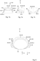
- the hip shells 84-1, 84-2 are designed and held on the textile part 82 in such a way that the hip shells 84-1, 84-2 are positioned ventrally (cf. arrow 72 in Fig.8 ) into a groin area 92 of the operator 12, that dorsally (cf. arrow 74 in Fig.7 ) directed forces can be introduced into the body of the operator 12 via the hip shells 84-1, 84-2.
- the hip shells 84-1, 84-2 are preferably mounted on the textile part 82 in such a way that by moving the hip shells 84-1, 84-2 relative to the textile part 82, a position of the lower connection points 30-1, 30-2 can be changed both laterally or medially relative to the median plane 50 and anteriorly or posteriorly relative to the frontal plane 52 (in Fig.8 indicated by the double arrow 96).
- the lower body connection 18 also includes an optional lumbar support 100, which is part of the lower force distribution device 58.
- the lumbar support 100 is held on the textile part 82 and is force-coupled via this to the hip shells 84-1, 84-2.
- the lumbar support 100 can also be connected to the hip shells 84-1, 84-2 via one or more elastic bands 102 (see. Fig. 7a ).
- the lumbar support 100 is, for example and preferably, mounted on the textile part 82 in such a way that it can be moved in such a way that the lumbar support 100 can be positioned cranially (see arrow 36 in Fig. 7a ) or caudal (see arrow 104 in Fig. 7a ) is changeable, in particular adjustable.
- the first support 22-1 can optionally be connected to the upper body connection 20 at the first upper connection point 32-1 via a first upper joint device 106-1 and the second support 22-2 can optionally be connected to the upper body connection 20 at the second upper connection point 32-2 via a second upper joint device 106-2.
- the upper joint devices 106-1, 106-2 each have three joint degrees of freedom.
- the upper body connection can comprise a first adjustment mechanism (not shown) which is designed to change a distance between the first and second upper joint device 106-1, 106-2.
- the upper Body connection 20 has a similar rack mechanism as the lower body connection 18 (cf. Fig.6 and description above).
- the upper body connection 20 may also comprise a second upper adjustment mechanism (not shown) which is designed to adjust a position of the upper joint devices 106-1, 106-2 anteriorly (cf. arrow 72 in Fig.5 ) or posterior (see arrow 74 in Fig.5 ) relative to the frontal plane 52.
- a particularly advantageous effect of the auxiliary device 10 can result from an interaction between the lower and upper body connection 18, 20.
- Fig.9 Schematically shown, it is possible, for example, to recreate body anatomies with narrow hips and a broad back.
Landscapes
- Engineering & Computer Science (AREA)
- Robotics (AREA)
- Mechanical Engineering (AREA)
- Orthopedics, Nursing, And Contraception (AREA)
- Manipulator (AREA)
Claims (15)
- Dispositif d'aide (10) mettable destiné à supporter le levage et/ou le maintien de charges (14) par un opérateur (12), comprenant- une structure de support (16) avec un premier support (22-1) et un deuxième support (22-2), dans lequel le premier support (22-1) et le deuxième support (22-2) présentent chacun une section dorsale (24 -1, 24-2) et une section de flèche (26-1, 26-2) de telle sorte que, lorsque le dispositif d'aide (10) est mis par l'opérateur (12), la section dorsale (24-1, 24-2) est disposée en arrière et s'étend pour l'essentiel le long de la partie de dos de l'opérateur (12) et la section de flèche (26-1, 26-2) s'étend de l'arrière vers l'avant;- une attache inférieure au corps (18) pour coupler la structure de support (16) à une zone pelvienne, de la hanche et/ou lombaire de l'opérateur (12);- une attache supérieure au corps (20) pour coupler la structure de support (16) à un haut du corps de l'opérateur (12), en particulier à une zone du dos, des épaules et/ou de la poitrine;- une première attache à la main (40-1) pour être attachée à une zone de la main droite ou de l'avant-bras droit de l'opérateur (12), dans lequel la première attache à la main (40-1) est reliée au premier support (22-1) par le biais d'un premier dispositif de liaison (42-1) réglable en longueur;- une deuxième attache à la main (40-2) pour être attachée à une zone de la main gauche ou de l'avant-bras gauche de l'opérateur (12), dans lequel la deuxième attache à la main (40-2) est reliée au deuxième support (22-2) par le biais d'un deuxième dispositif de liaison (42-2) réglable en longueur,dans lequel le premier support (22-1) est relié à l'attache inférieure au corps (18) au niveau d'un premier point de liaison inférieur (30-1) et dans lequel le deuxième support (22-2) est relié à l'attache inférieure au corps (18) au niveau d'un deuxième point de liaison inférieur (30-2), dans lequel l'attache inférieure au corps (18) est conçue de telle sorte qu'une position relative du premier point de liaison inférieur (30-1) et du deuxième point de liaison inférieur (30-2) peut être modifiée.
- Dispositif d'aide (10) mettable selon la revendication 1, dans lequel l'attache inférieure au corps (18) est conçue de telle sorte qu'une distance séparant le premier point de liaison inférieur (30-1) et le deuxième point de liaison inférieur (30-2) est modifiable, en particulier réglable.
- Dispositif d'aide (10) mettable selon la revendication 1 ou 2, dans lequel l'attache inférieure au corps (18) est conçue de telle sorte qu'une position relative du premier point de liaison inférieur (30-1) et du deuxième point de liaison inférieur (30- 2) est modifiable, en particulier une position du premier point de liaison inférieur (30-1) et/ou du deuxième point de liaison inférieur (30-2), lorsque le dispositif d'aide (10) est mis, peut être modifiée, en outre en particulier réglée, latéralement et médialement par rapport au plan médian (50) et/ou en direction antérieure et en direction postérieure par rapport au plan frontal (52), en particulier de manière indépendante l'une de l'autre.
- Dispositif d'aide (10) mettable selon l'une quelconque des revendications précédentes, dans lequel le premier support (22-1) et le deuxième support (22-2) sont reliés de manière articulée à l'attache inférieure au corps, en particulier dans lequel le premier support (22-1) est relié au niveau d'un premier point de liaison inférieur (30-1), via un premier dispositif d'articulation inférieur (48-1), à l'attache inférieure au corps (18), et dans lequel le deuxième support (22-2) est relié au niveau d'un deuxième point de liaison inférieur (30-2), via un deuxième dispositif d'articulation inférieur (48-2), à l'attache inférieure au corps (18).
- Dispositif d'aide (10) mettable selon l'une quelconque des revendications précédentes, dans lequel l'attache inférieure au corps (18) comprend un dispositif inférieur de répartition de force (58) qui est relié aux supports (22-1, 22-2), en particulier par l'intermédiaire des dispositifs d'articulation inférieurs (48-1, 48-2), et dans lequel l'attache inférieure au corps (18) comprend un dispositif inférieur flexible d'attache au corps (80) qui est relié au dispositif de répartition de force inférieur (58) et destiné à être attaché à une zone du corps de l'opérateur (12).
- Dispositif d'aide (10) mettable selon la revendication 5, dans lequel le dispositif inférieur d'attache au corps (80) comprend au moins une partie textile, en particulier sous la forme d'une ceinture, d'un système de ceinture ou d'une manchette.
- Dispositif d'aide (10) mettable selon l'une quelconque des revendications 5 ou 6, dans lequel le dispositif inférieur de répartition de force (58) présente un corps de base inférieur (60) qui s'étend entre le premier support (22-1) et le deuxième support (22-2) et sur lequel sont disposés les supports (22-1, 22-2), en particulier par l'intermédiaire des dispositifs d'articulation inférieurs (48-1, 48-2).
- Dispositif d'aide (10) mettable selon la revendication 7, dans lequel le corps de base inférieur (60) comprend un premier mécanisme inférieur de réglage (64) qui est conçu pour modifier, en particulier régler, une distance séparant les points de liaison inférieurs (30-1, 30- 2), en outre en particulier pour modifier la position des points de liaison inférieurs (30-1, 30-2) latéralement et médialement par rapport au plan médian (50) .
- Dispositif d'aide (10) mettable selon l'une quelconque des revendications précédentes, dans lequel les supports (22-1, 22-2), en particulier avec les dispositifs d'articulation inférieurs (48-1, 48-2), sont maintenus chacun par un dispositif de pivotement (62-1, 62-2) sur l'attache inférieure au corps (18), en particulier sur le corps de base inférieur (60), dans lequel ledit dispositif de pivotement (62-1, 62-2) est conçu pour modifier une position du point de liaison inférieur (30-1, 30-2) en direction antérieure et en direction postérieure par rapport au plan frontal (52).
- Dispositif d'aide (10) mettable selon l'une quelconque des revendications 5 ou 6, dans lequel le dispositif de répartition de force inférieur (58) comprend une première coque de hanche (84-1) destinée à être en appui sur une zone de hanche droite de l'opérateur (12) et une deuxième coque de hanche (84-2) destinée à être en appui sur une zone de hanche gauche de l'opérateur (12), dans lequel le premier support (22-1) est relié à la première coque de hanche (84-1) par l'intermédiaire du premier dispositif d'articulation inférieur (48-1) et dans lequel le deuxième support (22-2) est relié à la deuxième coque de hanche (84-2) par l'intermédiaire du deuxième dispositif d'articulation inférieur (48-2), en particulier dans lequel les coques de hanche (84 -1, 84-2) sont conçues de telle sorte que, lorsque le dispositif d'aide (10) est mis, les coques de hanche (84-1, 84-2) font saillie de manière ventrale dans une zone de l'aine (92) de l'opérateur (12) de telle manière que des forces dirigées vers le dos peuvent être appliquées par les coques de hanche (84-1, 84-2) au corps de l'opérateur (12).
- Dispositif d'aide (10) mettable selon la revendication 10, dans lequel les première et deuxième coques de hanche (84-1, 84-2) sont maintenues de manière coulissante sur le dispositif inférieur d'attache au corps (18), en particulier sur ladite au moins une partie textile (82), en particulier de telle manière que, en déplaçant la première et/ou la deuxième coque de hanche (84-1, 84-2) par rapport au dispositif inférieur d'attache au corps (18), une distance séparant les points de liaison inférieurs (30-1, 30-2) l'un par rapport à l'autre, peut être modifiée, en particulier réglée, notamment latéralement et médialement par rapport au plan médian (50) et/ou en direction antérieure et en direction postérieure par rapport au plan frontal (52).
- Dispositif d'aide (10) mettable selon l'une quelconque des revendications 10 ou 11, dans lequel le dispositif de répartition de force inférieur (58) comprend en outre au moins un support lombaire (100) qui est couplé par force via le dispositif inférieur d'attache au corps (80) à la première et/ou la deuxième coque de hanche (84-1, 84-2), en particulier dans lequel ledit au moins un support lombaire (100) est maintenu sur le dispositif inférieur d'attache au corps (80), en particulier sur ladite au moins une partie textile (82), de manière à être crânialement et/ou caudalement déplaçable.
- Dispositif d'aide (10) mettable selon l'une quelconque des revendications précédentes, dans lequel le premier support (22-1) est relié au niveau d'un premier point de liaison supérieur (32-1), en particulier de manière articulée, en outre en particulier via un premier dispositif d'articulation supérieur (106-1), à l'attache supérieure au corps (20), et dans lequel le deuxième support (22-2) est relié au niveau d'un deuxième point de liaison supérieur (32-2), en particulier de manière articulée, en outre en particulier via un deuxième dispositif d'articulation supérieur (106-2), à l'attache supérieure au corps (20)
- Dispositif d'aide (10) mettable selon la revendication 13, dans lequel l'attache supérieure au corps (20) est conçue de telle sorte qu'une position relative du premier point de liaison supérieur (32-1) et du deuxième point de liaison supérieur (32-2) est modifiable, en particulier une position du premier point de liaison supérieur (32-1) et/ou du deuxième point de liaison supérieur (32-2), lorsque le dispositif d'aide (10) est mis, peut être modifiée, en particulier réglée, latéralement et médialement par rapport au plan médian (50) et/ou en direction antérieure et en direction postérieure par rapport au plan frontal (52), en particulier de manière indépendante l'une de l'autre.
- Dispositif d'aide mettable selon l'une quelconque des revendications précédentes, dans lequel les attaches supérieure et inférieure au corps (18, 20) sont conçues de telle sorte qu'une position relative des points de liaison supérieurs (32-1, 32-2) et une position relative des points de liaison inférieurs (30-1, 30-2) peuvent être modifiées, en particulier réglées, indépendamment l'une de l'autre.
Applications Claiming Priority (1)
| Application Number | Priority Date | Filing Date | Title |
|---|---|---|---|
| DE102022100205.5A DE102022100205A1 (de) | 2022-01-05 | 2022-01-05 | Anziehbare Hilfsvorrichtung mit verstellbarer unterer Körperanbindung |
Publications (3)
| Publication Number | Publication Date |
|---|---|
| EP4209310A1 EP4209310A1 (fr) | 2023-07-12 |
| EP4209310B1 true EP4209310B1 (fr) | 2024-07-17 |
| EP4209310C0 EP4209310C0 (fr) | 2024-07-17 |
Family
ID=81877866
Family Applications (1)
| Application Number | Title | Priority Date | Filing Date |
|---|---|---|---|
| EP22176855.9A Active EP4209310B1 (fr) | 2022-01-05 | 2022-06-01 | Dispositif d'aide amovible à raccordement réglable du corps inférieur |
Country Status (3)
| Country | Link |
|---|---|
| EP (1) | EP4209310B1 (fr) |
| JP (1) | JP2023100239A (fr) |
| DE (1) | DE102022100205A1 (fr) |
Family Cites Families (12)
| Publication number | Priority date | Publication date | Assignee | Title |
|---|---|---|---|---|
| WO2013035814A1 (fr) * | 2011-09-06 | 2013-03-14 | 国立大学法人 和歌山大学 | Dispositif robotique à assistance de puissance et procédé de commande de celui-ci |
| WO2014195373A1 (fr) | 2013-06-07 | 2014-12-11 | J. Schmalz | Aide au levage portée sur le corps |
| JP6153881B2 (ja) * | 2014-03-20 | 2017-06-28 | 株式会社クボタ | アシストスーツ |
| WO2016113954A1 (fr) * | 2015-01-14 | 2016-07-21 | 株式会社クボタ | Combinaison d'assistance |
| KR102312527B1 (ko) * | 2015-05-18 | 2021-10-14 | 더 리전츠 오브 더 유니버시티 오브 캘리포니아 | 인간 팔 지지 외골격용 방법 및 장치 |
| JP6754563B2 (ja) * | 2015-11-20 | 2020-09-16 | 株式会社クボタ | アシストスーツ |
| JP6657036B2 (ja) * | 2016-06-28 | 2020-03-04 | 株式会社クボタ | アシスト器具 |
| DE102016121203A1 (de) | 2016-11-07 | 2018-05-09 | Otto Bock Healthcare Gmbh | Vorrichtung zum Unterstützen eines Armes |
| WO2018157302A1 (fr) * | 2017-02-28 | 2018-09-07 | 深圳龙海特机器人科技有限公司 | Dispositif de transport auxiliaire pouvant être porté, doté de deux ouvertures |
| DE102017112436B4 (de) * | 2017-06-06 | 2019-05-29 | Ottobock Se & Co. Kgaa | Vorrichtung zum Unterstützen wenigstens eines Armes eines Benutzers |
| DE102019113913A1 (de) | 2018-05-28 | 2019-11-28 | Jtekt Corporation | Unterstützungsvorrichtung |
| JP2020093375A (ja) * | 2018-12-14 | 2020-06-18 | 株式会社ジェイテクト | アシスト装置 |
-
2022
- 2022-01-05 DE DE102022100205.5A patent/DE102022100205A1/de active Pending
- 2022-06-01 EP EP22176855.9A patent/EP4209310B1/fr active Active
- 2022-06-03 JP JP2022091207A patent/JP2023100239A/ja active Pending
Also Published As
| Publication number | Publication date |
|---|---|
| DE102022100205A1 (de) | 2023-07-06 |
| EP4209310A1 (fr) | 2023-07-12 |
| JP2023100239A (ja) | 2023-07-18 |
| EP4209310C0 (fr) | 2024-07-17 |
Similar Documents
| Publication | Publication Date | Title |
|---|---|---|
| DE102017112436B4 (de) | Vorrichtung zum Unterstützen wenigstens eines Armes eines Benutzers | |
| WO2017157941A1 (fr) | Exosquelette pour être humain | |
| WO2020035284A1 (fr) | Dispositif de soutien d'au moins un bras d'un utilisateur | |
| EP4232245B1 (fr) | Aide portable | |
| EP4209310B1 (fr) | Dispositif d'aide amovible à raccordement réglable du corps inférieur | |
| EP4169416B1 (fr) | Dispositif d'assistance au transport de charges | |
| EP4209311B1 (fr) | Dispositif d'aide amovible à raccordement réglable du corps supérieur | |
| EP4228867B1 (fr) | Aide portable | |
| DE3918346A1 (de) | Tragevorrichtung | |
| EP4157591A1 (fr) | Mécanisme de support de bras | |
| DE102021202433B3 (de) | Extremitätenunterstützungsvorrichtung und Verfahren zum Heben, Halten und/oder Tragen einer Last und/oder zum Ausführen von Überkopftätigkeiten | |
| WO2020035298A1 (fr) | Dispositif destiné à soutenir au moins un bras d'un utilisateur | |
| WO2023025904A2 (fr) | Système d'assistance au portage | |
| DE102022100202A1 (de) | Anziehbare Hilfsvorrichtung | |
| EP3873390B1 (fr) | Orthèse de genou | |
| DE102004027105B4 (de) | Rucksack | |
| DE3911780A1 (de) | Vorrichtung zur unterstuetzung von bewegungen | |
| DE10049302B4 (de) | Tragesystem | |
| DE102024110072B4 (de) | Modulares Rückenorthesensystem mit Rückenorthesenvorrichtung und Lastaufnahmemodul sowie entsprechendes Lastaufnahmemodul | |
| DE20219321U1 (de) | Vorrichtung für die lösbare Anordnung einer Transporteinrichtung an einem Menschen | |
| DE202024101772U1 (de) | Rückenorthesenvorrichtung mit Lastaufnahmemodul, entsprechendes Lastaufnahmemodul, sowie Verwendung zum Abstützen insbesondere persönlicher Schutzausrüstung wie z.B. einer (Röntgen-)Schürze | |
| DE102021120725A1 (de) | Vorrichtung zur Behandlung der menschlichen Wirbelsäule | |
| DE102016105353A1 (de) | Orthese | |
| DE10065645A1 (de) | Der Rucksack mit verschiebbarem Schwerpunkt und abnehmbaren Trägern in der Größe entsprechend seiner Körpergröße |
Legal Events
| Date | Code | Title | Description |
|---|---|---|---|
| PUAI | Public reference made under article 153(3) epc to a published international application that has entered the european phase |
Free format text: ORIGINAL CODE: 0009012 |
|
| STAA | Information on the status of an ep patent application or granted ep patent |
Free format text: STATUS: THE APPLICATION HAS BEEN PUBLISHED |
|
| AK | Designated contracting states |
Kind code of ref document: A1 Designated state(s): AL AT BE BG CH CY CZ DE DK EE ES FI FR GB GR HR HU IE IS IT LI LT LU LV MC MK MT NL NO PL PT RO RS SE SI SK SM TR |
|
| STAA | Information on the status of an ep patent application or granted ep patent |
Free format text: STATUS: REQUEST FOR EXAMINATION WAS MADE |
|
| 17P | Request for examination filed |
Effective date: 20231115 |
|
| RBV | Designated contracting states (corrected) |
Designated state(s): AL AT BE BG CH CY CZ DE DK EE ES FI FR GB GR HR HU IE IS IT LI LT LU LV MC MK MT NL NO PL PT RO RS SE SI SK SM TR |
|
| GRAP | Despatch of communication of intention to grant a patent |
Free format text: ORIGINAL CODE: EPIDOSNIGR1 |
|
| STAA | Information on the status of an ep patent application or granted ep patent |
Free format text: STATUS: GRANT OF PATENT IS INTENDED |
|
| INTG | Intention to grant announced |
Effective date: 20240202 |
|
| GRAS | Grant fee paid |
Free format text: ORIGINAL CODE: EPIDOSNIGR3 |
|
| GRAA | (expected) grant |
Free format text: ORIGINAL CODE: 0009210 |
|
| STAA | Information on the status of an ep patent application or granted ep patent |
Free format text: STATUS: THE PATENT HAS BEEN GRANTED |
|
| AK | Designated contracting states |
Kind code of ref document: B1 Designated state(s): AL AT BE BG CH CY CZ DE DK EE ES FI FR GB GR HR HU IE IS IT LI LT LU LV MC MK MT NL NO PL PT RO RS SE SI SK SM TR |
|
| REG | Reference to a national code |
Ref country code: CH Ref legal event code: EP |
|
| REG | Reference to a national code |
Ref country code: DE Ref legal event code: R096 Ref document number: 502022001240 Country of ref document: DE |
|
| REG | Reference to a national code |
Ref country code: IE Ref legal event code: FG4D Free format text: LANGUAGE OF EP DOCUMENT: GERMAN |
|
| U01 | Request for unitary effect filed |
Effective date: 20240815 |
|
| U07 | Unitary effect registered |
Designated state(s): AT BE BG DE DK EE FI FR IT LT LU LV MT NL PT SE SI Effective date: 20240827 |
|
| PG25 | Lapsed in a contracting state [announced via postgrant information from national office to epo] |
Ref country code: NO Free format text: LAPSE BECAUSE OF FAILURE TO SUBMIT A TRANSLATION OF THE DESCRIPTION OR TO PAY THE FEE WITHIN THE PRESCRIBED TIME-LIMIT Effective date: 20241017 |
|
| PG25 | Lapsed in a contracting state [announced via postgrant information from national office to epo] |
Ref country code: PL Free format text: LAPSE BECAUSE OF FAILURE TO SUBMIT A TRANSLATION OF THE DESCRIPTION OR TO PAY THE FEE WITHIN THE PRESCRIBED TIME-LIMIT Effective date: 20240717 Ref country code: GR Free format text: LAPSE BECAUSE OF FAILURE TO SUBMIT A TRANSLATION OF THE DESCRIPTION OR TO PAY THE FEE WITHIN THE PRESCRIBED TIME-LIMIT Effective date: 20241018 |
|
| PG25 | Lapsed in a contracting state [announced via postgrant information from national office to epo] |
Ref country code: IS Free format text: LAPSE BECAUSE OF FAILURE TO SUBMIT A TRANSLATION OF THE DESCRIPTION OR TO PAY THE FEE WITHIN THE PRESCRIBED TIME-LIMIT Effective date: 20241117 |
|
| PG25 | Lapsed in a contracting state [announced via postgrant information from national office to epo] |
Ref country code: HR Free format text: LAPSE BECAUSE OF FAILURE TO SUBMIT A TRANSLATION OF THE DESCRIPTION OR TO PAY THE FEE WITHIN THE PRESCRIBED TIME-LIMIT Effective date: 20240717 |
|
| PG25 | Lapsed in a contracting state [announced via postgrant information from national office to epo] |
Ref country code: ES Free format text: LAPSE BECAUSE OF FAILURE TO SUBMIT A TRANSLATION OF THE DESCRIPTION OR TO PAY THE FEE WITHIN THE PRESCRIBED TIME-LIMIT Effective date: 20240717 Ref country code: RS Free format text: LAPSE BECAUSE OF FAILURE TO SUBMIT A TRANSLATION OF THE DESCRIPTION OR TO PAY THE FEE WITHIN THE PRESCRIBED TIME-LIMIT Effective date: 20241017 |
|
| PG25 | Lapsed in a contracting state [announced via postgrant information from national office to epo] |
Ref country code: RS Free format text: LAPSE BECAUSE OF FAILURE TO SUBMIT A TRANSLATION OF THE DESCRIPTION OR TO PAY THE FEE WITHIN THE PRESCRIBED TIME-LIMIT Effective date: 20241017 Ref country code: PL Free format text: LAPSE BECAUSE OF FAILURE TO SUBMIT A TRANSLATION OF THE DESCRIPTION OR TO PAY THE FEE WITHIN THE PRESCRIBED TIME-LIMIT Effective date: 20240717 Ref country code: NO Free format text: LAPSE BECAUSE OF FAILURE TO SUBMIT A TRANSLATION OF THE DESCRIPTION OR TO PAY THE FEE WITHIN THE PRESCRIBED TIME-LIMIT Effective date: 20241017 Ref country code: IS Free format text: LAPSE BECAUSE OF FAILURE TO SUBMIT A TRANSLATION OF THE DESCRIPTION OR TO PAY THE FEE WITHIN THE PRESCRIBED TIME-LIMIT Effective date: 20241117 Ref country code: HR Free format text: LAPSE BECAUSE OF FAILURE TO SUBMIT A TRANSLATION OF THE DESCRIPTION OR TO PAY THE FEE WITHIN THE PRESCRIBED TIME-LIMIT Effective date: 20240717 Ref country code: GR Free format text: LAPSE BECAUSE OF FAILURE TO SUBMIT A TRANSLATION OF THE DESCRIPTION OR TO PAY THE FEE WITHIN THE PRESCRIBED TIME-LIMIT Effective date: 20241018 Ref country code: ES Free format text: LAPSE BECAUSE OF FAILURE TO SUBMIT A TRANSLATION OF THE DESCRIPTION OR TO PAY THE FEE WITHIN THE PRESCRIBED TIME-LIMIT Effective date: 20240717 |
|
| PG25 | Lapsed in a contracting state [announced via postgrant information from national office to epo] |
Ref country code: SM Free format text: LAPSE BECAUSE OF FAILURE TO SUBMIT A TRANSLATION OF THE DESCRIPTION OR TO PAY THE FEE WITHIN THE PRESCRIBED TIME-LIMIT Effective date: 20240717 |
|
| PG25 | Lapsed in a contracting state [announced via postgrant information from national office to epo] |
Ref country code: CZ Free format text: LAPSE BECAUSE OF FAILURE TO SUBMIT A TRANSLATION OF THE DESCRIPTION OR TO PAY THE FEE WITHIN THE PRESCRIBED TIME-LIMIT Effective date: 20240717 |
|
| PG25 | Lapsed in a contracting state [announced via postgrant information from national office to epo] |
Ref country code: SK Free format text: LAPSE BECAUSE OF FAILURE TO SUBMIT A TRANSLATION OF THE DESCRIPTION OR TO PAY THE FEE WITHIN THE PRESCRIBED TIME-LIMIT Effective date: 20240717 |
|
| PLBE | No opposition filed within time limit |
Free format text: ORIGINAL CODE: 0009261 |
|
| STAA | Information on the status of an ep patent application or granted ep patent |
Free format text: STATUS: NO OPPOSITION FILED WITHIN TIME LIMIT |
|
| 26N | No opposition filed |
Effective date: 20250422 |
|
| U20 | Renewal fee for the european patent with unitary effect paid |
Year of fee payment: 4 Effective date: 20250623 |
|
| REG | Reference to a national code |
Ref country code: CH Ref legal event code: H13 Free format text: ST27 STATUS EVENT CODE: U-0-0-H10-H13 (AS PROVIDED BY THE NATIONAL OFFICE) Effective date: 20260127 |
|
| PG25 | Lapsed in a contracting state [announced via postgrant information from national office to epo] |
Ref country code: MC Free format text: LAPSE BECAUSE OF FAILURE TO SUBMIT A TRANSLATION OF THE DESCRIPTION OR TO PAY THE FEE WITHIN THE PRESCRIBED TIME-LIMIT Effective date: 20240717 |
|
| PG25 | Lapsed in a contracting state [announced via postgrant information from national office to epo] |
Ref country code: IE Free format text: LAPSE BECAUSE OF NON-PAYMENT OF DUE FEES Effective date: 20250601 |
|
| PG25 | Lapsed in a contracting state [announced via postgrant information from national office to epo] |
Ref country code: RO Free format text: LAPSE BECAUSE OF FAILURE TO SUBMIT A TRANSLATION OF THE DESCRIPTION OR TO PAY THE FEE WITHIN THE PRESCRIBED TIME-LIMIT Effective date: 20240717 |
|
| PG25 | Lapsed in a contracting state [announced via postgrant information from national office to epo] |
Ref country code: CH Free format text: LAPSE BECAUSE OF NON-PAYMENT OF DUE FEES Effective date: 20250630 |