EP4209332B1 - Dispositif d'irradiation pour un appareil de fabrication additive d'objets tridimensionnels - Google Patents
Dispositif d'irradiation pour un appareil de fabrication additive d'objets tridimensionnels Download PDFInfo
- Publication number
- EP4209332B1 EP4209332B1 EP23159637.0A EP23159637A EP4209332B1 EP 4209332 B1 EP4209332 B1 EP 4209332B1 EP 23159637 A EP23159637 A EP 23159637A EP 4209332 B1 EP4209332 B1 EP 4209332B1
- Authority
- EP
- European Patent Office
- Prior art keywords
- stream
- irradiation
- housing
- irradiation device
- gas stream
- Prior art date
- Legal status (The legal status is an assumption and is not a legal conclusion. Google has not performed a legal analysis and makes no representation as to the accuracy of the status listed.)
- Active
Links
Images
Classifications
-
- B—PERFORMING OPERATIONS; TRANSPORTING
- B29—WORKING OF PLASTICS; WORKING OF SUBSTANCES IN A PLASTIC STATE IN GENERAL
- B29C—SHAPING OR JOINING OF PLASTICS; SHAPING OF MATERIAL IN A PLASTIC STATE, NOT OTHERWISE PROVIDED FOR; AFTER-TREATMENT OF THE SHAPED PRODUCTS, e.g. REPAIRING
- B29C64/00—Additive manufacturing, i.e. manufacturing of three-dimensional [3D] objects by additive deposition, additive agglomeration or additive layering, e.g. by 3D printing, stereolithography or selective laser sintering
- B29C64/10—Processes of additive manufacturing
- B29C64/141—Processes of additive manufacturing using only solid materials
- B29C64/153—Processes of additive manufacturing using only solid materials using layers of powder being selectively joined, e.g. by selective laser sintering or melting
-
- B—PERFORMING OPERATIONS; TRANSPORTING
- B22—CASTING; POWDER METALLURGY
- B22F—WORKING METALLIC POWDER; MANUFACTURE OF ARTICLES FROM METALLIC POWDER; MAKING METALLIC POWDER; APPARATUS OR DEVICES SPECIALLY ADAPTED FOR METALLIC POWDER
- B22F12/00—Apparatus or devices specially adapted for additive manufacturing; Auxiliary means for additive manufacturing; Combinations of additive manufacturing apparatus or devices with other processing apparatus or devices
- B22F12/38—Housings, e.g. machine housings
-
- B—PERFORMING OPERATIONS; TRANSPORTING
- B29—WORKING OF PLASTICS; WORKING OF SUBSTANCES IN A PLASTIC STATE IN GENERAL
- B29C—SHAPING OR JOINING OF PLASTICS; SHAPING OF MATERIAL IN A PLASTIC STATE, NOT OTHERWISE PROVIDED FOR; AFTER-TREATMENT OF THE SHAPED PRODUCTS, e.g. REPAIRING
- B29C64/00—Additive manufacturing, i.e. manufacturing of three-dimensional [3D] objects by additive deposition, additive agglomeration or additive layering, e.g. by 3D printing, stereolithography or selective laser sintering
- B29C64/20—Apparatus for additive manufacturing; Details thereof or accessories therefor
- B29C64/25—Housings, e.g. machine housings
-
- B—PERFORMING OPERATIONS; TRANSPORTING
- B29—WORKING OF PLASTICS; WORKING OF SUBSTANCES IN A PLASTIC STATE IN GENERAL
- B29C—SHAPING OR JOINING OF PLASTICS; SHAPING OF MATERIAL IN A PLASTIC STATE, NOT OTHERWISE PROVIDED FOR; AFTER-TREATMENT OF THE SHAPED PRODUCTS, e.g. REPAIRING
- B29C64/00—Additive manufacturing, i.e. manufacturing of three-dimensional [3D] objects by additive deposition, additive agglomeration or additive layering, e.g. by 3D printing, stereolithography or selective laser sintering
- B29C64/20—Apparatus for additive manufacturing; Details thereof or accessories therefor
- B29C64/264—Arrangements for irradiation
-
- B—PERFORMING OPERATIONS; TRANSPORTING
- B29—WORKING OF PLASTICS; WORKING OF SUBSTANCES IN A PLASTIC STATE IN GENERAL
- B29C—SHAPING OR JOINING OF PLASTICS; SHAPING OF MATERIAL IN A PLASTIC STATE, NOT OTHERWISE PROVIDED FOR; AFTER-TREATMENT OF THE SHAPED PRODUCTS, e.g. REPAIRING
- B29C64/00—Additive manufacturing, i.e. manufacturing of three-dimensional [3D] objects by additive deposition, additive agglomeration or additive layering, e.g. by 3D printing, stereolithography or selective laser sintering
- B29C64/20—Apparatus for additive manufacturing; Details thereof or accessories therefor
- B29C64/264—Arrangements for irradiation
- B29C64/268—Arrangements for irradiation using laser beams; using electron beams [EB]
-
- B—PERFORMING OPERATIONS; TRANSPORTING
- B29—WORKING OF PLASTICS; WORKING OF SUBSTANCES IN A PLASTIC STATE IN GENERAL
- B29C—SHAPING OR JOINING OF PLASTICS; SHAPING OF MATERIAL IN A PLASTIC STATE, NOT OTHERWISE PROVIDED FOR; AFTER-TREATMENT OF THE SHAPED PRODUCTS, e.g. REPAIRING
- B29C64/00—Additive manufacturing, i.e. manufacturing of three-dimensional [3D] objects by additive deposition, additive agglomeration or additive layering, e.g. by 3D printing, stereolithography or selective laser sintering
- B29C64/30—Auxiliary operations or equipment
- B29C64/35—Cleaning
-
- B—PERFORMING OPERATIONS; TRANSPORTING
- B29—WORKING OF PLASTICS; WORKING OF SUBSTANCES IN A PLASTIC STATE IN GENERAL
- B29C—SHAPING OR JOINING OF PLASTICS; SHAPING OF MATERIAL IN A PLASTIC STATE, NOT OTHERWISE PROVIDED FOR; AFTER-TREATMENT OF THE SHAPED PRODUCTS, e.g. REPAIRING
- B29C64/00—Additive manufacturing, i.e. manufacturing of three-dimensional [3D] objects by additive deposition, additive agglomeration or additive layering, e.g. by 3D printing, stereolithography or selective laser sintering
- B29C64/30—Auxiliary operations or equipment
- B29C64/386—Data acquisition or data processing for additive manufacturing
- B29C64/393—Data acquisition or data processing for additive manufacturing for controlling or regulating additive manufacturing processes
-
- B—PERFORMING OPERATIONS; TRANSPORTING
- B22—CASTING; POWDER METALLURGY
- B22F—WORKING METALLIC POWDER; MANUFACTURE OF ARTICLES FROM METALLIC POWDER; MAKING METALLIC POWDER; APPARATUS OR DEVICES SPECIALLY ADAPTED FOR METALLIC POWDER
- B22F10/00—Additive manufacturing of workpieces or articles from metallic powder
- B22F10/30—Process control
- B22F10/32—Process control of the atmosphere, e.g. composition or pressure in a building chamber
-
- B—PERFORMING OPERATIONS; TRANSPORTING
- B22—CASTING; POWDER METALLURGY
- B22F—WORKING METALLIC POWDER; MANUFACTURE OF ARTICLES FROM METALLIC POWDER; MAKING METALLIC POWDER; APPARATUS OR DEVICES SPECIALLY ADAPTED FOR METALLIC POWDER
- B22F10/00—Additive manufacturing of workpieces or articles from metallic powder
- B22F10/70—Recycling
- B22F10/77—Recycling of gas
-
- B—PERFORMING OPERATIONS; TRANSPORTING
- B22—CASTING; POWDER METALLURGY
- B22F—WORKING METALLIC POWDER; MANUFACTURE OF ARTICLES FROM METALLIC POWDER; MAKING METALLIC POWDER; APPARATUS OR DEVICES SPECIALLY ADAPTED FOR METALLIC POWDER
- B22F12/00—Apparatus or devices specially adapted for additive manufacturing; Auxiliary means for additive manufacturing; Combinations of additive manufacturing apparatus or devices with other processing apparatus or devices
- B22F12/40—Radiation means
- B22F12/49—Scanners
-
- B—PERFORMING OPERATIONS; TRANSPORTING
- B22—CASTING; POWDER METALLURGY
- B22F—WORKING METALLIC POWDER; MANUFACTURE OF ARTICLES FROM METALLIC POWDER; MAKING METALLIC POWDER; APPARATUS OR DEVICES SPECIALLY ADAPTED FOR METALLIC POWDER
- B22F2201/00—Treatment under specific atmosphere
- B22F2201/10—Inert gases
- B22F2201/11—Argon
-
- B—PERFORMING OPERATIONS; TRANSPORTING
- B29—WORKING OF PLASTICS; WORKING OF SUBSTANCES IN A PLASTIC STATE IN GENERAL
- B29C—SHAPING OR JOINING OF PLASTICS; SHAPING OF MATERIAL IN A PLASTIC STATE, NOT OTHERWISE PROVIDED FOR; AFTER-TREATMENT OF THE SHAPED PRODUCTS, e.g. REPAIRING
- B29C64/00—Additive manufacturing, i.e. manufacturing of three-dimensional [3D] objects by additive deposition, additive agglomeration or additive layering, e.g. by 3D printing, stereolithography or selective laser sintering
- B29C64/30—Auxiliary operations or equipment
- B29C64/364—Conditioning of environment
- B29C64/371—Conditioning of environment using an environment other than air, e.g. inert gas
-
- B—PERFORMING OPERATIONS; TRANSPORTING
- B33—ADDITIVE MANUFACTURING TECHNOLOGY
- B33Y—ADDITIVE MANUFACTURING, i.e. MANUFACTURING OF THREE-DIMENSIONAL [3D] OBJECTS BY ADDITIVE DEPOSITION, ADDITIVE AGGLOMERATION OR ADDITIVE LAYERING, e.g. BY 3D PRINTING, STEREOLITHOGRAPHY OR SELECTIVE LASER SINTERING
- B33Y10/00—Processes of additive manufacturing
-
- B—PERFORMING OPERATIONS; TRANSPORTING
- B33—ADDITIVE MANUFACTURING TECHNOLOGY
- B33Y—ADDITIVE MANUFACTURING, i.e. MANUFACTURING OF THREE-DIMENSIONAL [3D] OBJECTS BY ADDITIVE DEPOSITION, ADDITIVE AGGLOMERATION OR ADDITIVE LAYERING, e.g. BY 3D PRINTING, STEREOLITHOGRAPHY OR SELECTIVE LASER SINTERING
- B33Y30/00—Apparatus for additive manufacturing; Details thereof or accessories therefor
-
- B—PERFORMING OPERATIONS; TRANSPORTING
- B33—ADDITIVE MANUFACTURING TECHNOLOGY
- B33Y—ADDITIVE MANUFACTURING, i.e. MANUFACTURING OF THREE-DIMENSIONAL [3D] OBJECTS BY ADDITIVE DEPOSITION, ADDITIVE AGGLOMERATION OR ADDITIVE LAYERING, e.g. BY 3D PRINTING, STEREOLITHOGRAPHY OR SELECTIVE LASER SINTERING
- B33Y40/00—Auxiliary operations or equipment, e.g. for material handling
-
- B—PERFORMING OPERATIONS; TRANSPORTING
- B33—ADDITIVE MANUFACTURING TECHNOLOGY
- B33Y—ADDITIVE MANUFACTURING, i.e. MANUFACTURING OF THREE-DIMENSIONAL [3D] OBJECTS BY ADDITIVE DEPOSITION, ADDITIVE AGGLOMERATION OR ADDITIVE LAYERING, e.g. BY 3D PRINTING, STEREOLITHOGRAPHY OR SELECTIVE LASER SINTERING
- B33Y50/00—Data acquisition or data processing for additive manufacturing
- B33Y50/02—Data acquisition or data processing for additive manufacturing for controlling or regulating additive manufacturing processes
-
- Y—GENERAL TAGGING OF NEW TECHNOLOGICAL DEVELOPMENTS; GENERAL TAGGING OF CROSS-SECTIONAL TECHNOLOGIES SPANNING OVER SEVERAL SECTIONS OF THE IPC; TECHNICAL SUBJECTS COVERED BY FORMER USPC CROSS-REFERENCE ART COLLECTIONS [XRACs] AND DIGESTS
- Y02—TECHNOLOGIES OR APPLICATIONS FOR MITIGATION OR ADAPTATION AGAINST CLIMATE CHANGE
- Y02P—CLIMATE CHANGE MITIGATION TECHNOLOGIES IN THE PRODUCTION OR PROCESSING OF GOODS
- Y02P10/00—Technologies related to metal processing
- Y02P10/25—Process efficiency
Definitions
- the invention relates to an irradiation device for an apparatus for additively manufacturing three-dimensional objects by means of successive layerwise selective irradiation and consolidation of layers of a build material which can be consolidated by means of an energy source, which irradiation device comprises at least one irradiation unit, preferably an optical unit, arranged in a housing of the irradiation device.
- Apparatuses for additively manufacturing three-dimensional objects, e.g. via successive selective irradiation of layers of a build material, e.g. via an energy beam are generally known from prior art.
- Such apparatuses comprise irradiation devices for providing an energy source, such as a laser source or an electron source, for consolidating the build material.
- irradiation devices comprise housings in which irradiation units, e.g. various optical and electronic components of the irradiation device, such as beam guiding units, in particular scanners, lenses and lens assemblies and the like, can be arranged.
- the housing of the irradiation device further is used to protect the irradiation units arranged inside the housing, e.g. from the process environment in the process chamber of the apparatus, in particular involving high temperatures due to the melting process, soot, smoke and smolder, build material particles and the like. Additionally, the housing partially protects the irradiation units from residues contained in the ambient air, such as dust or other particles. Housings of irradiation devices known from prior art may further be manufactured nearly gas tight, but it is still necessary to regularly clean the irradiation units from the residues present in the ambient air inside the housing, e.g. dust deposited on (optical) surfaces of the irradiation units.
- Document WO 2016/026668 A1 discloses an irradiation device in accordance with the preamble of claim 1.
- the irradiation device described herein is an irradiation device for an apparatus for additively manufacturing three-dimensional objects, e.g. technical components, by means of successive selective layerwise consolidation of layers of a powdered build material ("build material") which can be consolidated by means of an energy source, e.g. an energy beam, in particular a laser beam or an electron beam.
- a respective build material can be a metal, ceramic or polymer powder.
- a respective energy beam can be a laser beam or an electron beam.
- a respective apparatus can be an apparatus in which an application of build material and a consolidation of build material is performed separately, such as a selective laser sintering apparatus, a selective laser melting apparatus or a selective electron beam melting apparatus, for instance.
- the successive layerwise selective consolidation of build material may be performed via at least one binding material.
- the binding material may be applied with a corresponding application unit and, for example, irradiated with a suitable energy source, e.g. a UV light source.
- Such an apparatus may comprise a number of functional units which are used during its operation.
- exemplary functional units are a process chamber, an inventive irradiation device, as described before, which may be adapted to selectively irradiate a build material layer disposed in the process chamber with at least one energy beam, and a stream generating device which is adapted to generate a gaseous fluid stream at least partly streaming through the process chamber with given streaming properties, e.g. a given streaming profile, streaming velocity, etc.
- the gaseous fluid stream is capable of being charged with non-consolidated particulate build material, particularly smoke or smoke residues generated during operation of the apparatus, while streaming through the process chamber.
- the gaseous fluid stream is typically inert, i.e. typically a stream of an inert gas, e.g. argon, nitrogen, carbon dioxide, etc.
- the invention relates to an irradiation device for an additive manufacturing apparatus providing a housing in which at least one irradiation unit, for example an optical unit, is arranged.
- the invention is based on the idea that a stream generating device is provided, in particular a stream generating device that is coupled or can be coupled with the irradiation device, in particular the housing of the irradiation device.
- the stream generating device is adapted to guide a gas stream that is adapted to be charged with residues present inside the housing through the housing of the irradiation device along a streaming path in which the gas stream is at least partially streamed alongside or through the at least one irradiation unit for removing residues from the housing.
- the stream generating device may be used to generate a gas stream, preferably a stream of ambient air that can be sucked or blown into the housing of the irradiation device.
- the gas stream can be charged with residues that are present inside the housing, for example particulate residues, such as dust particles, that may otherwise adhere to surfaces of the irradiation unit, in particular surfaces of lenses, thereby, negatively influencing the process quality and the object quality of the object that is additively manufactured during the additive manufacturing process performed with the irradiation device.
- the stream generating device generates the gas stream in that the gas stream streams along a streaming path in which the gas stream at least partially streams alongside or through the at least one irradiation unit.
- the gas stream is streamed in that it is guided alongside or through the at least one irradiation unit for picking up and conveying residues present in that region around the irradiation unit and removing those residues from the irradiation unit.
- the gas stream is guided through the housing and out of the housing in that residues that are picked up via the gas stream can efficiently be removed from the housing.
- the housing further may be built gas tight in that the stream generating device may be used to generate an overpressure inside the housing.
- the stream generating device may be used to generate an overpressure inside the housing.
- residues such as dust particles and the like can enter the housing from outside.
- the term "irradiation unit" in the scope of this application may refer to any arbitrary part of the irradiation device, in particular optical units, such as lenses or mirrors, beam splitters and the like, or other (opto-) electronic units, for instance.
- the gas stream can be streamed alongside or through those components of the irradiation device it is possible to on the one hand pick up and convey free (floating) residues present inside the housing and further remove residues already adhered to surfaces of an irradiation unit and thereby actively remove residues from the irradiation unit.
- the process quality and object quality may be improved, as negative impacts caused by residues present in the housing can significantly be reduced.
- downtimes of the irradiation device and therefore, downtimes of the entire apparatus the irradiation device is assigned to can be avoided or reduced, as the need for cleaning of the housing of the irradiation device, in particular cleaning the irradiation unit(s), can significantly be reduced or even entirely avoided.
- the stream generating device is adapted to adjust a position and/or an orientation, in particular a streaming direction, of at least one part of the streaming path dependent on the residue travel direction or a position and/or an orientation, in particular a streaming direction, of at least one part of the streaming path is defined dependent on a residue travel direction.
- the stream generating device may adjust the gas stream, in particular a position of at least one part of the gas stream, e.g. a position that lies in the gas stream and that the gas stream is guided along or through on its way along the streaming path.
- an orientation of the streaming path or at least one part of the streaming path can be adjusted via the stream generating device, for example the streaming direction in which the gas stream is streamed through the housing of the irradiation device.
- the adjustment of the position and/or the orientation of the at least one part of the streaming path is performed dependent on the residue travel direction.
- the residue travel direction in the scope of this application may refer to a most probable or determined direction in which the residues present inside the housing are most likely traveling. For example, due to gravity, residues may travel from the ceiling to the bottom of the housing thereby, adhering to a surface of the at least one irradiation unit. Thus, it is possible to take the residue travel direction into calculation and adjust the position and/or the orientation of the at least one part of the streaming path accordingly.
- the stream generating device may initially be built in a predefined configuration that allows for guiding the gas stream along a defined streaming path which is defined dependent on the residue travel direction.
- the inventive irradiation device may further be improved in that the streaming path may at least partially extend from a bottom region to a top region of the housing, in particular from a floor to a ceiling of the housing.
- the streaming path may preferably extend in the opposite direction, thereby picking up residues traveling along the residue travel direction and removing those residues from the housing.
- the stream generating device of the inventive irradiation device may further comprise at least one stream inlet assigned to an inlet region and at least one stream outlet assigned to an outlet region of the housing.
- at least one stream inlet assigned to an inlet region and at least one stream outlet assigned to an outlet region of the housing.
- the gas stream may be sucked from or blown out of the housing through the at least one stream outlet which is assigned to an outlet region of the housing.
- the stream generating device of the inventive irradiation device may comprise at least two stream inlets and at least one stream outlet.
- the gas stream may more homogeneously stream through the housing of the process chamber, wherein the positive effects of the gas stream on the irradiation unit, for example removing the residues from the housing and tempering the at least one irradiation unit can further be improved.
- the at least two stream inlets may preferably be arranged in two different wall structures of the housing, wherein the at least two stream inlets are preferably arranged in opposite or facing wall structures, e.g. sidewalls of the housing of the irradiation device.
- the at least one stream outlet is arranged in a ceiling structure of the housing for ensuring that, as described before, the gas stream may be streamed from a bottom region, in which the at least two stream inlets may be arranged, e.g. in a bottom half of the housing, to the ceiling of the housing.
- At least one stream inlet or the at least one stream outlet may comprise or be built as a diffusor element, adapted to distribute the gas stream that streams from or into the stream inlet or a stream outlet over a defined streaming area, thereby preferably enlarging the streaming area for enabling a homogeneous flow of the gas stream through the housing.
- the at least one stream inlet or stream outlet may comprise at least two stream vents, preferably a plurality of stream vents.
- the at least two vents may preferably be arranged as a vent array, in particular comprising a plurality of stream vents.
- a wall structure or the ceiling of the irradiation device may comprise a vent array or the vent array may be arranged in the ceiling or at least one wall structure of the housing of the irradiation device.
- the streaming properties of the gas stream are more uniform in different areas inside the housing of the irradiation device, e.g. the streaming velocity or the flow rate of the gas stream is essentially uniform throughout the housing.
- the stream generating device of the inventive irradiation device may further comprise at least one separating device that is adapted to separate, in particular filter, residues from the gas stream.
- the gas stream can be filtered, wherein residues the gas stream is charged with, can be separated from the gas stream.
- the at least one separating device is arranged on an inlet side or an inlet region of the stream generating device, e.g. in advance to the at least one stream inlet with respect to the streaming direction of the gas stream.
- the separating device may, inter alia, comprise at least one separating unit that comprises at least one cyclone separator and/or a filter unit that comprises a filter element.
- the filter element may, for example, be built as or include at least one of an EPA and/or HEPA and/or ULPA element for removing residues, such as dust particles and the like, from the gas stream.
- the separating device may, according to another embodiment of the inventive irradiation device, comprise an open gas circuit, preferably with the separating unit arranged in advance to the gas inlet, or a closed gas circuit.
- an open gas circuit preferably with the separating unit arranged in advance to the gas inlet, or a closed gas circuit.
- the gas stream may be streamed from the environment through the at least one separating unit into the housing and removed from the housing through the at least one gas outlet.
- the gas stream that is brought from the environment of the housing into the housing of the irradiation device is free of residues, such as dust particles, as the separating unit that is arranged in advance to the gas inlet, may separate, in particular filter, the residues present in the gas stream in that the gas stream that is fed into the housing is essentially free of residues.
- the stream generating device comprise a closed gas circuit.
- gas circuit may refer to any circuit through which the gas can be streamed, e.g. involving a pipe structure or a channel structure adapted to guide the gas stream.
- the closed gas stream my preferably involve a pipe structure or a general structure that connects of the at least one stream outlet with the at least one stream inlet in that the gas stream that exits the housing through the at least one stream outlet is fed back to the at least one stream inlet, wherein the gas stream passes the at least one separating device in that the residues the gas stream is charged with can be removed from the gas stream and thereby, removed from the housing.
- the irradiation unit may be or may comprise at least one scanner unit, preferably an x- and y-scanner, e.g. involving at least one movable mirror element that can be used to scan the energy beam across the build plane. It is further possible that the irradiation unit is or comprises at least one optical unit, in particular a lens or a lens assembly. Thus, the term "irradiation unit" may refer to any arbitrary component of the irradiation device that is arranged inside the housing. Therefore, it is possible to use the gas stream for removing residues from the irradiation unit, e.g.
- a movable mirror or a lens or a lens assembly in that the quality of the additive manufacturing process, in particular the quality of the object that is manufactured during the additive manufacturing process, can meet defined requirements throughout the entire additive manufacturing process. Hence, integration of the process quality and/or optical quality due to residues adhering to an irradiation unit can be avoided or significantly reduced.
- the inventive irradiation device may further be improved in that the stream generating device comprises a tempering unit adapted to temper, in particular to cool, the gas stream to a defined target temperature.
- the gas stream can be used to cool the irradiation unit of the irradiation device, e.g. assuring that the irradiation unit of the irradiation device remains on a stable target temperature.
- negative effects such as thermal elongation of components of the irradiation device, e.g. lenses or optical mirror elements, can be avoided or at least significantly reduced. Therefore, the process quality and the object quality can be enhanced, as negative thermal effects can be avoided or at least reduced.
- the stream generating device may preferably be adapted to control at least one property of the gas stream, preferably a flow rate and/or a streaming velocity and/or a temperature of the gas stream, dependent on at least one tempering parameter, preferably the temperature of the gas stream and/or the temperature of the at least one irradiation unit.
- a temperature of the irradiation unit and/or the temperature of the gas stream can be determined and the stream generating device, e.g. a tempering unit, can be used to control the gas stream dependent on the determined parameters. For example, it is possible to change the flow rate and/or the streaming velocity and/or the temperature of the gas stream dependent on the determined parameter.
- at least one irradiation unit e.g.
- an optical component of the irradiation device is heating up above a defined threshold temperature, the gas stream can be streamed faster or the flow rate of the gas stream can be increased to dissipate heat from the irradiation unit. It is also possible to change the temperature of the gas stream that is streamed through the housing of the irradiation device to further transport heat away from the irradiation unit, for instance.
- the invention relates to an apparatus for additively manufacturing three-dimensional objects by means of successive layerwise selective irradiation and consolidation of layers of a build material which can be consolidated by means of an energy source, wherein an irradiation device is provided that comprises at least one irradiation unit, preferably an optical unit, arranged in a housing of the irradiation device, wherein the irradiation device comprises a stream generating device that is adapted to guide a gas stream that is adapted to be charged with residues present inside the housing through the housing of the irradiation device along a streaming path in which the gas stream at least partially streams alongside or through the at least one irradiation unit for removing residues from the housing.
- an irradiation device comprises at least one irradiation unit, preferably an optical unit, arranged in a housing of the irradiation device, wherein the irradiation device comprises a stream generating device that is adapted to guide a gas stream that is adapted to be charged with
- the invention relates to a method for operating an apparatus for additively manufacturing three-dimensional objects by means of successive layerwise selective irradiation and consolidation of layers of a build material which can be consolidated by means of an energy source, which apparatus comprises an irradiation device that comprises at least one irradiation unit, preferably an optical unit, arranged in a housing of the irradiation device, wherein a gas stream is guided through the housing of the irradiation device along a streaming path along which the gas stream at least partially streams alongside or through the at least one irradiation unit, wherein the generated gas stream is charged with residues present inside the housing for removing the residues.
- an irradiation device that comprises at least one irradiation unit, preferably an optical unit, arranged in a housing of the irradiation device, wherein a gas stream is guided through the housing of the irradiation device along a streaming path along which the gas stream at least partially streams alongside or through the at least one irradiation unit,
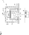
- FIG. 1 is a schematic diagram showing an inventive apparatus with an inventive irradiation device.
- the Fig. shows an apparatus 1 for additively manufacturing three-dimensional objects 2 by means of successive layerwise selective irradiation and consolidation of layers of a build material 3 via an energy source, e.g. by means of an energy beam 4.
- the apparatus 1 comprises an irradiation device 5 comprising three irradiation units 6, 7, 8 arranged in a housing 9 of the irradiation device 5.
- the irradiation unit 6 is a laser source that is adapted to generate the energy beam 4
- the irradiation unit 7 is a lens assembly through which the energy beam 4 is guided
- the irradiation unit 8 is exemplary for a beam guiding unit, e.g. a scanner unit.
- the irradiation device 5 further comprises a stream generating unit 10 that is adapted to generate a gas stream 11 that streams through a pipe structure 12 to two stream inlets 13 that are arranged in opposite wall structures 14 of the housing 9.
- the gas stream 11 streams through the inside of the housing 9 and thereby, streams alongside the irradiation units 6 - 8 to a stream outlet 15.
- the stream outlet 15 comprises a plurality of stream vents 16 through which the gas stream 11 can exit the housing 9.
- the stream generating device 10 further comprises a separating device 17 which is adapted to separate residues present in the housing 9 from the gas stream 11.
- the separating device 17 for example comprises a filter unit with a filter element, e.g. a HEPA filter element, that is adapted to filter particulate residues from the gas stream 11.
- the separating device 17 may further comprise a cyclone separator to further enhance the removal of residues the gas stream 11 is charged with.
- the gas stream 11 is guided into the housing 9 of the irradiation device 5 and thereby, can be charged with residues, such as dust particles.
- the residues the gas stream 11 is charged with may be removed from the housing 9 to ensure that the residues cannot adhere to surfaces of the irradiation units 6, 7 and 8.
- the gas stream 11 can be used to remove already adhered residues from the irradiation units 6 - 8 or other components of the housing 9.
- the process window 18 can also be deemed an irradiation unit in the scope of this application.
- the stream generating device 10 comprises a stream generating unit 20, e.g. a pump adapted to generate the gas stream 11. Further, the stream generating device 10 may involve a tempering unit 21 that is adapted to temper the gas stream 11, in particular cool the gas stream 11 to a defined target temperature. Thus, it is possible that the gas stream 11 is tempered to the defined target temperature, wherein the irradiation units 6 - 8 may also be tempered, in particular cooled, via the gas stream 11.
- the stream generating device 10 can adjust various parameters of the gas stream 11, in particular the streaming velocity and/or the flow rate and/or the temperature of the gas stream 11, preferably dependent on a determined parameter inside the housing 9, for example the actual temperature of the gas stream 11 or the temperature of at least one of the irradiation unit 6 - 8, for instance.
- the apparatus 1 is adapted to perform the inventive method.
Landscapes
- Engineering & Computer Science (AREA)
- Chemical & Material Sciences (AREA)
- Materials Engineering (AREA)
- Physics & Mathematics (AREA)
- Optics & Photonics (AREA)
- Manufacturing & Machinery (AREA)
- Mechanical Engineering (AREA)
- Health & Medical Sciences (AREA)
- Toxicology (AREA)
- Plasma & Fusion (AREA)
- Environmental & Geological Engineering (AREA)
Claims (14)
- Dispositif d'irradiation (5) pour un appareil (1) de fabrication additive d'objets tridimensionnels (2) par irradiation sélective par couches successives et consolidation de couches d'un matériau de construction (3) pouvant être consolidé au moyen d'une source d'énergie, lequel dispositif d'irradiation (5) comprend au moins une unité d'irradiation (6 - 8), de préférence une unité optique, disposée dans un boîtier (9) du dispositif d'irradiation (5), dans lequel un dispositif de génération de flux (10) adapté pour guider un flux de gaz (11) adapté pour être chargé de résidus présents à l'intérieur du boîtier (9) à travers le boîtier (9) du dispositif d'irradiation (5) le long d'une trajectoire de flux dans laquelle le flux de gaz (11) s'écoule au moins partiellement le long ou à travers l'au moins une unité d'irradiation (6 - 8) pour éliminer les résidus du boîtier (9), caractérisé par le fait que le dispositif de génération de flux (10) est adapté pour ajuster une position et/ou une orientation, en particulier une direction de flux, d'au moins une partie de la trajectoire de flux en fonction d'une direction de déplacement des résidus ou une position et/ou une orientation, en particulier une direction de flux, d'au moins une partie de la trajectoire de flux est définie en fonction d'une direction de déplacement des résidus.
- Dispositif d'irradiation selon la revendication 1, caractérisé par le fait que le dispositif de génération de flux (10) est adapté pour tempérer au moins une unité d'irradiation (6 - 8) par le biais du flux de gaz (11).
- Dispositif d'irradiation selon l'une des revendications précédentes, caractérisé en ce que le dispositif de génération de flux (10) comprend au moins une entrée de flux (13) affectée à une zone d'entrée et au moins une sortie de flux (15) affectée à une zone de sortie du boîtier (9).
- Dispositif d'irradiation selon l'une des revendications précédentes, caractérisé en ce que le dispositif de génération de flux (10) comprend au moins deux entrées de flux (13) et au moins une sortie de flux (15).
- Dispositif d'irradiation selon la revendication 3 ou 4, caractérisé en ce que les au moins deux entrées de flux (13) sont disposées dans deux structures murales (14) différentes du boîtier (9) et/ou en ce que la au moins une sortie de flux (15) est disposée dans une structure de plafond du boîtier (9).
- Dispositif d'irradiation selon l'une des revendications 3 à 5, caractérisé en ce que l'au moins une entrée (13) ou sortie de flux comprend au moins deux évents (16), de préférence une pluralité d'évents (16).
- Dispositif d'irradiation selon l'une des revendications 6, caractérisé en ce que les au moins deux évents (16) sont disposés comme un réseau d'évents.
- Dispositif d'irradiation selon l'une des revendications précédentes, caractérisé en ce que le dispositif de génération de flux (10) comprend au moins un dispositif de séparation (17) qui est adapté pour séparer, en particulier filtrer, les résidus du flux de gaz (11).
- Dispositif d'irradiation selon l'une des revendications 7 ou 8, caractérisé en ce que le dispositif de génération de flux (10) comprend un circuit de gaz ouvert, de préférence avec le dispositif de séparation (17) disposé en amont de l'entrée de gaz, ou un circuit de gaz fermé.
- Dispositif d'irradiation selon l'une des revendications précédentes, caractérisé en ce que l'unité d'irradiation (6 - 8) est ou comprend un scanner, de préférence un scanner x et y, et/ou au moins une unité optique, en particulier une lentille ou un ensemble de lentilles.
- Dispositif d'irradiation selon l'une des revendications précédentes, caractérisé par le fait que le dispositif de génération de flux (10) comprend une unité de trempe (21) adaptée pour tremper, en particulier pour refroidir, le flux de gaz (11) à une température cible définie.
- Dispositif d'irradiation selon la revendication 11, caractérisé en ce que le dispositif de génération de flux (10) est adapté pour contrôler au moins une propriété du flux gazeux (11), de préférence un débit et/ou une vitesse d'écoulement et/ou la température du flux gazeux (11), en fonction d'au moins un paramètre de tempérage, de préférence la température du flux gazeux (11) et/ou la température d'au moins une unité d'irradiation (6 - 8).
- Appareil (1) de fabrication additive d'objets tridimensionnels (2) par irradiation sélective successive par couches et consolidation de couches d'un matériau de construction (3) pouvant être consolidé au moyen d'une source d'énergie, comprenant un dispositif d'irradiation (5) selon l'une des revendications précédentes.
- Procédé de fonctionnement d'un appareil (1) de fabrication additive d'objets tridimensionnels (2) par irradiation sélective et consolidation de couches successives d'un matériau de construction (3) pouvant être consolidé au moyen d'une source d'énergie, lequel appareil (1) comprend un dispositif d'irradiation (5) qui comprend au moins une unité d'irradiation (6 - 8), de préférence une unité optique, disposée dans un boîtier (9) du dispositif d'irradiation (5), caractérisé par le guidage d'un flux gazeux généré (11) à travers le boîtier (9) du dispositif d'irradiation (5) le long d'une trajectoire de flux le long de laquelle le flux gazeux (11) s'écoule au moins partiellement le long ou à travers la au moins une unité d'irradiation (6 - 8), dans lequel le flux de gaz généré (11) est chargé de résidus présents à l'intérieur du boîtier (9) pour éliminer les résidus, dans lequel un dispositif de génération de flux (10) est adapté pour ajuster une position et/ou une orientation, en particulier une direction de flux, d'au moins une partie de la trajectoire de flux en fonction d'une direction de déplacement des résidus ou une position et/ou une orientation, en particulier une direction de flux, d'au moins une partie de la trajectoire de flux est définie en fonction d'une direction de déplacement des résidus.
Priority Applications (1)
| Application Number | Priority Date | Filing Date | Title |
|---|---|---|---|
| EP23159637.0A EP4209332B1 (fr) | 2018-11-21 | 2018-11-21 | Dispositif d'irradiation pour un appareil de fabrication additive d'objets tridimensionnels |
Applications Claiming Priority (2)
| Application Number | Priority Date | Filing Date | Title |
|---|---|---|---|
| EP23159637.0A EP4209332B1 (fr) | 2018-11-21 | 2018-11-21 | Dispositif d'irradiation pour un appareil de fabrication additive d'objets tridimensionnels |
| EP18207633.1A EP3656539B1 (fr) | 2018-11-21 | 2018-11-21 | Dispositif de rayonnement pour un appareil de fabrication additive d'objets tridimensionnels |
Related Parent Applications (2)
| Application Number | Title | Priority Date | Filing Date |
|---|---|---|---|
| EP18207633.1A Division-Into EP3656539B1 (fr) | 2018-11-21 | 2018-11-21 | Dispositif de rayonnement pour un appareil de fabrication additive d'objets tridimensionnels |
| EP18207633.1A Division EP3656539B1 (fr) | 2018-11-21 | 2018-11-21 | Dispositif de rayonnement pour un appareil de fabrication additive d'objets tridimensionnels |
Publications (2)
| Publication Number | Publication Date |
|---|---|
| EP4209332A1 EP4209332A1 (fr) | 2023-07-12 |
| EP4209332B1 true EP4209332B1 (fr) | 2024-10-16 |
Family
ID=64426809
Family Applications (2)
| Application Number | Title | Priority Date | Filing Date |
|---|---|---|---|
| EP23159637.0A Active EP4209332B1 (fr) | 2018-11-21 | 2018-11-21 | Dispositif d'irradiation pour un appareil de fabrication additive d'objets tridimensionnels |
| EP18207633.1A Active EP3656539B1 (fr) | 2018-11-21 | 2018-11-21 | Dispositif de rayonnement pour un appareil de fabrication additive d'objets tridimensionnels |
Family Applications After (1)
| Application Number | Title | Priority Date | Filing Date |
|---|---|---|---|
| EP18207633.1A Active EP3656539B1 (fr) | 2018-11-21 | 2018-11-21 | Dispositif de rayonnement pour un appareil de fabrication additive d'objets tridimensionnels |
Country Status (2)
| Country | Link |
|---|---|
| US (1) | US11504911B2 (fr) |
| EP (2) | EP4209332B1 (fr) |
Families Citing this family (6)
| Publication number | Priority date | Publication date | Assignee | Title |
|---|---|---|---|---|
| DE102014016679A1 (de) | 2014-11-12 | 2016-05-12 | Cl Schutzrechtsverwaltungs Gmbh | Verfahren und Vorrichtung zur Belichtungssteuerung einer selektiven Lasersinter- oder Laserschmelzvorrichtung |
| DE102016121770A1 (de) * | 2016-11-14 | 2018-05-17 | Cl Schutzrechtsverwaltungs Gmbh | Vorrichtung zur additiven Herstellung dreidimensionaler Objekte |
| EP3715095A1 (fr) * | 2019-03-27 | 2020-09-30 | Concept Laser GmbH | Appareil de fabrication additive d'objets tridimensionnels |
| GB2589625B (en) * | 2019-12-05 | 2021-10-27 | Xaar 3D Ltd | Improved thermal control for apparatus for the manufacture of three-dimensional objects |
| GB2593884B (en) * | 2020-04-02 | 2022-03-23 | Stratasys Powder Production Ltd | Extraction system for apparatus for the layer-by-layer formation of three-dimensional objects |
| US11752558B2 (en) | 2021-04-16 | 2023-09-12 | General Electric Company | Detecting optical anomalies on optical elements used in an additive manufacturing machine |
Family Cites Families (6)
| Publication number | Priority date | Publication date | Assignee | Title |
|---|---|---|---|---|
| DE102014000415A1 (de) * | 2014-01-17 | 2015-07-23 | Cl Schutzrechtsverwaltungs Gmbh | Vorrichtung zum Herstellen von dreidimensionalen Objekten durch aufeinanderfolgendes Verfestigen von Schichten |
| US20160052056A1 (en) * | 2014-08-22 | 2016-02-25 | Arcam Ab | Enhanced electron beam generation |
| US10738378B2 (en) * | 2016-07-08 | 2020-08-11 | Norsk Titanium As | Multi-chamber deposition equipment for solid free form fabrication |
| EP4049831A1 (fr) * | 2017-07-21 | 2022-08-31 | CL Schutzrechtsverwaltungs GmbH | Appareil de fabrication additive d'objets tridimensionnels |
| CN111315511B (zh) * | 2017-11-10 | 2022-08-12 | 通用电气公司 | 增材制造机器的气流系统 |
| US11298716B2 (en) * | 2018-08-21 | 2022-04-12 | General Electric Company | Flow directing system and method for additive manufacturing system |
-
2018
- 2018-11-21 EP EP23159637.0A patent/EP4209332B1/fr active Active
- 2018-11-21 EP EP18207633.1A patent/EP3656539B1/fr active Active
-
2019
- 2019-03-05 US US16/293,611 patent/US11504911B2/en active Active
Also Published As
| Publication number | Publication date |
|---|---|
| US20200156319A1 (en) | 2020-05-21 |
| EP3656539B1 (fr) | 2023-05-03 |
| US11504911B2 (en) | 2022-11-22 |
| EP3656539A1 (fr) | 2020-05-27 |
| EP4209332A1 (fr) | 2023-07-12 |
Similar Documents
| Publication | Publication Date | Title |
|---|---|---|
| EP4209332B1 (fr) | Dispositif d'irradiation pour un appareil de fabrication additive d'objets tridimensionnels | |
| CN107008900B (zh) | 用于生产三维工件的设备和方法 | |
| US11278965B2 (en) | Apparatus for producing a three-dimensional work piece with improved gas flow | |
| US9931789B2 (en) | Method and apparatus for producing a large three-dimensional work piece | |
| US9592636B2 (en) | Three dimensional printer | |
| US10569331B2 (en) | Three-dimensional printer | |
| EP2992942B1 (fr) | Appareil pour produire des pièces 3d par une méthode de fabrication additive comportant un circuit de recyclage de gaz amélioré | |
| CN105382258A (zh) | 包括干燥设备的用于生产工件的装置 | |
| CN108349161A (zh) | 用于制造三维物体的方法和设备 | |
| US11130289B2 (en) | Device for the generative production of a three-dimensional object | |
| US20200122397A1 (en) | Apparatus for additively manufacturing three-dimensional objects | |
| TWI802119B (zh) | 層疊造型裝置 | |
| US12290859B2 (en) | Powder application device, method for operating a powder application device, and system for producing a three-dimensional workpiece | |
| EP3572213B1 (fr) | Appareil de fabrication additive d'objets tridimensionnels et procédé de fonctionnement d'un appareil de fabrication additive | |
| CN116348224B (zh) | 操作辐照系统的方法、辐照系统以及用于生产三维工件的设备 | |
| US20200122398A1 (en) | Apparatus for additively manufacturing three-dimensional objects | |
| CN120659681A (zh) | 用于生产包括流动捕获器的三维工件的设备和方法 |
Legal Events
| Date | Code | Title | Description |
|---|---|---|---|
| PUAI | Public reference made under article 153(3) epc to a published international application that has entered the european phase |
Free format text: ORIGINAL CODE: 0009012 |
|
| STAA | Information on the status of an ep patent application or granted ep patent |
Free format text: STATUS: THE APPLICATION HAS BEEN PUBLISHED |
|
| AC | Divisional application: reference to earlier application |
Ref document number: 3656539 Country of ref document: EP Kind code of ref document: P |
|
| AK | Designated contracting states |
Kind code of ref document: A1 Designated state(s): AL AT BE BG CH CY CZ DE DK EE ES FI FR GB GR HR HU IE IS IT LI LT LU LV MC MK MT NL NO PL PT RO RS SE SI SK SM TR |
|
| STAA | Information on the status of an ep patent application or granted ep patent |
Free format text: STATUS: REQUEST FOR EXAMINATION WAS MADE |
|
| 17P | Request for examination filed |
Effective date: 20240108 |
|
| RBV | Designated contracting states (corrected) |
Designated state(s): AL AT BE BG CH CY CZ DE DK EE ES FI FR GB GR HR HU IE IS IT LI LT LU LV MC MK MT NL NO PL PT RO RS SE SI SK SM TR |
|
| GRAP | Despatch of communication of intention to grant a patent |
Free format text: ORIGINAL CODE: EPIDOSNIGR1 |
|
| STAA | Information on the status of an ep patent application or granted ep patent |
Free format text: STATUS: GRANT OF PATENT IS INTENDED |
|
| RIC1 | Information provided on ipc code assigned before grant |
Ipc: B22F 10/77 20210101ALN20240125BHEP Ipc: B22F 10/32 20210101ALN20240125BHEP Ipc: B33Y 30/00 20150101ALN20240125BHEP Ipc: B22F 12/00 20210101ALI20240125BHEP Ipc: B29C 64/371 20170101ALI20240125BHEP Ipc: B29C 64/264 20170101ALI20240125BHEP Ipc: B29C 64/25 20170101ALI20240125BHEP Ipc: B29C 64/153 20170101AFI20240125BHEP |
|
| RIC1 | Information provided on ipc code assigned before grant |
Ipc: B22F 10/77 20210101ALN20240210BHEP Ipc: B22F 10/32 20210101ALN20240210BHEP Ipc: B33Y 30/00 20150101ALN20240210BHEP Ipc: B22F 12/00 20210101ALI20240210BHEP Ipc: B29C 64/371 20170101ALI20240210BHEP Ipc: B29C 64/264 20170101ALI20240210BHEP Ipc: B29C 64/25 20170101ALI20240210BHEP Ipc: B29C 64/153 20170101AFI20240210BHEP |
|
| INTG | Intention to grant announced |
Effective date: 20240227 |
|
| GRAJ | Information related to disapproval of communication of intention to grant by the applicant or resumption of examination proceedings by the epo deleted |
Free format text: ORIGINAL CODE: EPIDOSDIGR1 |
|
| STAA | Information on the status of an ep patent application or granted ep patent |
Free format text: STATUS: REQUEST FOR EXAMINATION WAS MADE |
|
| GRAP | Despatch of communication of intention to grant a patent |
Free format text: ORIGINAL CODE: EPIDOSNIGR1 |
|
| STAA | Information on the status of an ep patent application or granted ep patent |
Free format text: STATUS: GRANT OF PATENT IS INTENDED |
|
| INTC | Intention to grant announced (deleted) | ||
| RIC1 | Information provided on ipc code assigned before grant |
Ipc: B22F 10/77 20210101ALN20240530BHEP Ipc: B22F 10/32 20210101ALN20240530BHEP Ipc: B33Y 30/00 20150101ALN20240530BHEP Ipc: B22F 12/00 20210101ALI20240530BHEP Ipc: B29C 64/371 20170101ALI20240530BHEP Ipc: B29C 64/264 20170101ALI20240530BHEP Ipc: B29C 64/25 20170101ALI20240530BHEP Ipc: B29C 64/153 20170101AFI20240530BHEP |
|
| INTG | Intention to grant announced |
Effective date: 20240612 |
|
| GRAS | Grant fee paid |
Free format text: ORIGINAL CODE: EPIDOSNIGR3 |
|
| GRAA | (expected) grant |
Free format text: ORIGINAL CODE: 0009210 |
|
| STAA | Information on the status of an ep patent application or granted ep patent |
Free format text: STATUS: THE PATENT HAS BEEN GRANTED |
|
| AC | Divisional application: reference to earlier application |
Ref document number: 3656539 Country of ref document: EP Kind code of ref document: P |
|
| AK | Designated contracting states |
Kind code of ref document: B1 Designated state(s): AL AT BE BG CH CY CZ DE DK EE ES FI FR GB GR HR HU IE IS IT LI LT LU LV MC MK MT NL NO PL PT RO RS SE SI SK SM TR |
|
| P01 | Opt-out of the competence of the unified patent court (upc) registered |
Free format text: CASE NUMBER: APP_51226/2024 Effective date: 20240910 |
|
| REG | Reference to a national code |
Ref country code: GB Ref legal event code: FG4D |
|
| REG | Reference to a national code |
Ref country code: CH Ref legal event code: EP |
|
| REG | Reference to a national code |
Ref country code: IE Ref legal event code: FG4D |
|
| REG | Reference to a national code |
Ref country code: DE Ref legal event code: R096 Ref document number: 602018075670 Country of ref document: DE |
|
| REG | Reference to a national code |
Ref country code: LT Ref legal event code: MG9D |
|
| REG | Reference to a national code |
Ref country code: NL Ref legal event code: MP Effective date: 20241016 |
|
| REG | Reference to a national code |
Ref country code: AT Ref legal event code: MK05 Ref document number: 1732606 Country of ref document: AT Kind code of ref document: T Effective date: 20241016 |
|
| PG25 | Lapsed in a contracting state [announced via postgrant information from national office to epo] |
Ref country code: NL Free format text: LAPSE BECAUSE OF FAILURE TO SUBMIT A TRANSLATION OF THE DESCRIPTION OR TO PAY THE FEE WITHIN THE PRESCRIBED TIME-LIMIT Effective date: 20241016 |
|
| PG25 | Lapsed in a contracting state [announced via postgrant information from national office to epo] |
Ref country code: NL Free format text: LAPSE BECAUSE OF FAILURE TO SUBMIT A TRANSLATION OF THE DESCRIPTION OR TO PAY THE FEE WITHIN THE PRESCRIBED TIME-LIMIT Effective date: 20241016 |
|
| PG25 | Lapsed in a contracting state [announced via postgrant information from national office to epo] |
Ref country code: PT Free format text: LAPSE BECAUSE OF FAILURE TO SUBMIT A TRANSLATION OF THE DESCRIPTION OR TO PAY THE FEE WITHIN THE PRESCRIBED TIME-LIMIT Effective date: 20250217 Ref country code: IS Free format text: LAPSE BECAUSE OF FAILURE TO SUBMIT A TRANSLATION OF THE DESCRIPTION OR TO PAY THE FEE WITHIN THE PRESCRIBED TIME-LIMIT Effective date: 20250216 Ref country code: HR Free format text: LAPSE BECAUSE OF FAILURE TO SUBMIT A TRANSLATION OF THE DESCRIPTION OR TO PAY THE FEE WITHIN THE PRESCRIBED TIME-LIMIT Effective date: 20241016 |
|
| PG25 | Lapsed in a contracting state [announced via postgrant information from national office to epo] |
Ref country code: FI Free format text: LAPSE BECAUSE OF FAILURE TO SUBMIT A TRANSLATION OF THE DESCRIPTION OR TO PAY THE FEE WITHIN THE PRESCRIBED TIME-LIMIT Effective date: 20241016 |
|
| PG25 | Lapsed in a contracting state [announced via postgrant information from national office to epo] |
Ref country code: BG Free format text: LAPSE BECAUSE OF FAILURE TO SUBMIT A TRANSLATION OF THE DESCRIPTION OR TO PAY THE FEE WITHIN THE PRESCRIBED TIME-LIMIT Effective date: 20241016 |
|
| PG25 | Lapsed in a contracting state [announced via postgrant information from national office to epo] |
Ref country code: ES Free format text: LAPSE BECAUSE OF FAILURE TO SUBMIT A TRANSLATION OF THE DESCRIPTION OR TO PAY THE FEE WITHIN THE PRESCRIBED TIME-LIMIT Effective date: 20241016 |
|
| PG25 | Lapsed in a contracting state [announced via postgrant information from national office to epo] |
Ref country code: NO Free format text: LAPSE BECAUSE OF FAILURE TO SUBMIT A TRANSLATION OF THE DESCRIPTION OR TO PAY THE FEE WITHIN THE PRESCRIBED TIME-LIMIT Effective date: 20250116 |
|
| PG25 | Lapsed in a contracting state [announced via postgrant information from national office to epo] |
Ref country code: LV Free format text: LAPSE BECAUSE OF FAILURE TO SUBMIT A TRANSLATION OF THE DESCRIPTION OR TO PAY THE FEE WITHIN THE PRESCRIBED TIME-LIMIT Effective date: 20241016 Ref country code: GR Free format text: LAPSE BECAUSE OF FAILURE TO SUBMIT A TRANSLATION OF THE DESCRIPTION OR TO PAY THE FEE WITHIN THE PRESCRIBED TIME-LIMIT Effective date: 20250117 Ref country code: AT Free format text: LAPSE BECAUSE OF FAILURE TO SUBMIT A TRANSLATION OF THE DESCRIPTION OR TO PAY THE FEE WITHIN THE PRESCRIBED TIME-LIMIT Effective date: 20241016 |
|
| PG25 | Lapsed in a contracting state [announced via postgrant information from national office to epo] |
Ref country code: PL Free format text: LAPSE BECAUSE OF FAILURE TO SUBMIT A TRANSLATION OF THE DESCRIPTION OR TO PAY THE FEE WITHIN THE PRESCRIBED TIME-LIMIT Effective date: 20241016 |
|
| PG25 | Lapsed in a contracting state [announced via postgrant information from national office to epo] |
Ref country code: RS Free format text: LAPSE BECAUSE OF FAILURE TO SUBMIT A TRANSLATION OF THE DESCRIPTION OR TO PAY THE FEE WITHIN THE PRESCRIBED TIME-LIMIT Effective date: 20250116 |
|
| REG | Reference to a national code |
Ref country code: CH Ref legal event code: PL |
|
| PG25 | Lapsed in a contracting state [announced via postgrant information from national office to epo] |
Ref country code: SM Free format text: LAPSE BECAUSE OF FAILURE TO SUBMIT A TRANSLATION OF THE DESCRIPTION OR TO PAY THE FEE WITHIN THE PRESCRIBED TIME-LIMIT Effective date: 20241016 |
|
| PG25 | Lapsed in a contracting state [announced via postgrant information from national office to epo] |
Ref country code: MC Free format text: LAPSE BECAUSE OF FAILURE TO SUBMIT A TRANSLATION OF THE DESCRIPTION OR TO PAY THE FEE WITHIN THE PRESCRIBED TIME-LIMIT Effective date: 20241016 |
|
| PG25 | Lapsed in a contracting state [announced via postgrant information from national office to epo] |
Ref country code: DK Free format text: LAPSE BECAUSE OF FAILURE TO SUBMIT A TRANSLATION OF THE DESCRIPTION OR TO PAY THE FEE WITHIN THE PRESCRIBED TIME-LIMIT Effective date: 20241016 |
|
| PG25 | Lapsed in a contracting state [announced via postgrant information from national office to epo] |
Ref country code: LU Free format text: LAPSE BECAUSE OF NON-PAYMENT OF DUE FEES Effective date: 20241121 |
|
| REG | Reference to a national code |
Ref country code: CH Ref legal event code: PL |
|
| REG | Reference to a national code |
Ref country code: DE Ref legal event code: R097 Ref document number: 602018075670 Country of ref document: DE |
|
| PG25 | Lapsed in a contracting state [announced via postgrant information from national office to epo] |
Ref country code: EE Free format text: LAPSE BECAUSE OF FAILURE TO SUBMIT A TRANSLATION OF THE DESCRIPTION OR TO PAY THE FEE WITHIN THE PRESCRIBED TIME-LIMIT Effective date: 20241016 |
|
| PG25 | Lapsed in a contracting state [announced via postgrant information from national office to epo] |
Ref country code: CH Free format text: LAPSE BECAUSE OF NON-PAYMENT OF DUE FEES Effective date: 20241130 |
|
| PG25 | Lapsed in a contracting state [announced via postgrant information from national office to epo] |
Ref country code: RO Free format text: LAPSE BECAUSE OF FAILURE TO SUBMIT A TRANSLATION OF THE DESCRIPTION OR TO PAY THE FEE WITHIN THE PRESCRIBED TIME-LIMIT Effective date: 20241016 |
|
| PG25 | Lapsed in a contracting state [announced via postgrant information from national office to epo] |
Ref country code: SK Free format text: LAPSE BECAUSE OF FAILURE TO SUBMIT A TRANSLATION OF THE DESCRIPTION OR TO PAY THE FEE WITHIN THE PRESCRIBED TIME-LIMIT Effective date: 20241016 |
|
| PG25 | Lapsed in a contracting state [announced via postgrant information from national office to epo] |
Ref country code: CZ Free format text: LAPSE BECAUSE OF FAILURE TO SUBMIT A TRANSLATION OF THE DESCRIPTION OR TO PAY THE FEE WITHIN THE PRESCRIBED TIME-LIMIT Effective date: 20241016 |
|
| PG25 | Lapsed in a contracting state [announced via postgrant information from national office to epo] |
Ref country code: IT Free format text: LAPSE BECAUSE OF FAILURE TO SUBMIT A TRANSLATION OF THE DESCRIPTION OR TO PAY THE FEE WITHIN THE PRESCRIBED TIME-LIMIT Effective date: 20241016 |
|
| PLBE | No opposition filed within time limit |
Free format text: ORIGINAL CODE: 0009261 |
|
| STAA | Information on the status of an ep patent application or granted ep patent |
Free format text: STATUS: NO OPPOSITION FILED WITHIN TIME LIMIT |
|
| REG | Reference to a national code |
Ref country code: BE Ref legal event code: MM Effective date: 20241130 |
|
| PG25 | Lapsed in a contracting state [announced via postgrant information from national office to epo] |
Ref country code: SE Free format text: LAPSE BECAUSE OF FAILURE TO SUBMIT A TRANSLATION OF THE DESCRIPTION OR TO PAY THE FEE WITHIN THE PRESCRIBED TIME-LIMIT Effective date: 20241016 |
|
| 26N | No opposition filed |
Effective date: 20250717 |
|
| GBPC | Gb: european patent ceased through non-payment of renewal fee |
Effective date: 20250116 |
|
| PG25 | Lapsed in a contracting state [announced via postgrant information from national office to epo] |
Ref country code: BE Free format text: LAPSE BECAUSE OF NON-PAYMENT OF DUE FEES Effective date: 20241130 Ref country code: GB Free format text: LAPSE BECAUSE OF NON-PAYMENT OF DUE FEES Effective date: 20250116 |
|
| PG25 | Lapsed in a contracting state [announced via postgrant information from national office to epo] |
Ref country code: FR Free format text: LAPSE BECAUSE OF NON-PAYMENT OF DUE FEES Effective date: 20241216 |
|
| PG25 | Lapsed in a contracting state [announced via postgrant information from national office to epo] |
Ref country code: IE Free format text: LAPSE BECAUSE OF NON-PAYMENT OF DUE FEES Effective date: 20241121 |
|
| PGFP | Annual fee paid to national office [announced via postgrant information from national office to epo] |
Ref country code: DE Payment date: 20251022 Year of fee payment: 8 |
|
| PG25 | Lapsed in a contracting state [announced via postgrant information from national office to epo] |
Ref country code: HU Free format text: LAPSE BECAUSE OF FAILURE TO SUBMIT A TRANSLATION OF THE DESCRIPTION OR TO PAY THE FEE WITHIN THE PRESCRIBED TIME-LIMIT; INVALID AB INITIO Effective date: 20181121 |
|
| PG25 | Lapsed in a contracting state [announced via postgrant information from national office to epo] |
Ref country code: CY Free format text: LAPSE BECAUSE OF FAILURE TO SUBMIT A TRANSLATION OF THE DESCRIPTION OR TO PAY THE FEE WITHIN THE PRESCRIBED TIME-LIMIT; INVALID AB INITIO Effective date: 20181121 |