EP4209367A1 - Procédé de déclenchement d'une soupape rtr, appareil de commande, système de ressort pneumatique et remorque - Google Patents
Procédé de déclenchement d'une soupape rtr, appareil de commande, système de ressort pneumatique et remorque Download PDFInfo
- Publication number
- EP4209367A1 EP4209367A1 EP22211841.6A EP22211841A EP4209367A1 EP 4209367 A1 EP4209367 A1 EP 4209367A1 EP 22211841 A EP22211841 A EP 22211841A EP 4209367 A1 EP4209367 A1 EP 4209367A1
- Authority
- EP
- European Patent Office
- Prior art keywords
- valve
- rtr
- reservoir
- pressure
- brake system
- Prior art date
- Legal status (The legal status is an assumption and is not a legal conclusion. Google has not performed a legal analysis and makes no representation as to the accuracy of the status listed.)
- Granted
Links
Images


Classifications
-
- B—PERFORMING OPERATIONS; TRANSPORTING
- B60—VEHICLES IN GENERAL
- B60G—VEHICLE SUSPENSION ARRANGEMENTS
- B60G17/00—Resilient suspensions having means for adjusting the spring or vibration-damper characteristics, for regulating the distance between a supporting surface and a sprung part of vehicle or for locking suspension during use to meet varying vehicular or surface conditions, e.g. due to speed or load
- B60G17/02—Spring characteristics, e.g. mechanical springs and mechanical adjusting means
- B60G17/04—Spring characteristics, e.g. mechanical springs and mechanical adjusting means fluid spring characteristics
- B60G17/052—Pneumatic spring characteristics
- B60G17/0523—Regulating distributors or valves for pneumatic springs
- B60G17/0525—Height adjusting or levelling valves
-
- B—PERFORMING OPERATIONS; TRANSPORTING
- B60—VEHICLES IN GENERAL
- B60G—VEHICLE SUSPENSION ARRANGEMENTS
- B60G17/00—Resilient suspensions having means for adjusting the spring or vibration-damper characteristics, for regulating the distance between a supporting surface and a sprung part of vehicle or for locking suspension during use to meet varying vehicular or surface conditions, e.g. due to speed or load
- B60G17/005—Suspension locking arrangements
-
- B—PERFORMING OPERATIONS; TRANSPORTING
- B60—VEHICLES IN GENERAL
- B60G—VEHICLE SUSPENSION ARRANGEMENTS
- B60G2202/00—Indexing codes relating to the type of spring, damper or actuator
- B60G2202/10—Type of spring
- B60G2202/15—Fluid spring
- B60G2202/152—Pneumatic spring
-
- B—PERFORMING OPERATIONS; TRANSPORTING
- B60—VEHICLES IN GENERAL
- B60G—VEHICLE SUSPENSION ARRANGEMENTS
- B60G2204/00—Indexing codes related to suspensions per se or to auxiliary parts
- B60G2204/40—Auxiliary suspension parts; Adjustment of suspensions
- B60G2204/46—Means for locking the suspension
-
- B—PERFORMING OPERATIONS; TRANSPORTING
- B60—VEHICLES IN GENERAL
- B60G—VEHICLE SUSPENSION ARRANGEMENTS
- B60G2300/00—Indexing codes relating to the type of vehicle
- B60G2300/04—Trailers
-
- B—PERFORMING OPERATIONS; TRANSPORTING
- B60—VEHICLES IN GENERAL
- B60G—VEHICLE SUSPENSION ARRANGEMENTS
- B60G2400/00—Indexing codes relating to detected, measured or calculated conditions or factors
- B60G2400/20—Speed
- B60G2400/204—Vehicle speed
-
- B—PERFORMING OPERATIONS; TRANSPORTING
- B60—VEHICLES IN GENERAL
- B60G—VEHICLE SUSPENSION ARRANGEMENTS
- B60G2400/00—Indexing codes relating to detected, measured or calculated conditions or factors
- B60G2400/25—Stroke; Height; Displacement
- B60G2400/252—Stroke; Height; Displacement vertical
-
- B—PERFORMING OPERATIONS; TRANSPORTING
- B60—VEHICLES IN GENERAL
- B60G—VEHICLE SUSPENSION ARRANGEMENTS
- B60G2500/00—Indexing codes relating to the regulated action or device
- B60G2500/30—Height or ground clearance
-
- B—PERFORMING OPERATIONS; TRANSPORTING
- B60—VEHICLES IN GENERAL
- B60G—VEHICLE SUSPENSION ARRANGEMENTS
- B60G2600/00—Indexing codes relating to particular elements, systems or processes used on suspension systems or suspension control systems
- B60G2600/02—Retarders, delaying means, dead zones, threshold values, cut-off frequency, timer interruption
Definitions
- the invention relates to a control device, an air spring system and a trailer vehicle.
- an actuating lever that can be moved by an operator can be moved back and forth between these positions.
- the height of the vehicle body is to be adapted to external conditions, for example to the level of a loading ramp or rail transport, which is to be carried out with the vehicle body lowered.
- the RtR valve should be in the driving position while driving. Only in the driving position does the RtR valve enable automatic leveling by means of an air suspension valve that is usually provided.
- the RtR valve can remain in the four positions outside of the driving position. It must therefore be ensured that a condition-dependent return to the driving position is possible.
- the RtR valve is designed in a special way and can be controlled by a control unit. When the trailer vehicle exceeds a certain minimum speed, the RtR valve automatically switches to the driving position. The name of the valve derives from this purpose.
- RtR means "Return to Ride” or "Reset to Ride".
- a locking device for the control lever is part of the RtR valve. Outside the driving position, the adjusting lever is loaded with a restoring force.
- the latching device holds the adjusting lever in position in such a way that the adjusting lever can still be adjusted by the operator, but cannot automatically return to the driving position.
- the Detent device are released, which is referred to here as triggering the RtR valve. It is triggered electro-pneumatically after exceeding the minimum speed.
- the supply of compressed air to an actuating cylinder of the latching device is controlled via a solenoid valve that can be controlled by an electrical pulse. As soon as compressed air is supplied, the detent mechanism is released and the RtR valve is actuated. The control lever can automatically return to the driving position if it was previously in a non-driving position.
- RtR valve with the aforementioned functions is, for example, in 1 the EP 3 643 543 B1 disclosed.
- the RtR valve is referred to as "valve device 1" in the associated description, the latching device as “locking valve 32" and "return-to-ride valve 33".
- the function of the detent device in connection with an RtR valve is also in 2 and 3 the DE 10 2010 011 433 A1 disclosed.
- the RtR valve is referred to as "valve device 6" in the associated description, the locking device as "locking device 30".
- the trailer vehicle has two reservoirs for compressed air, namely a reservoir for the brake system and a reservoir for the air suspension system or other ancillary consumers.
- the air tank for the brake system is first filled from the towing vehicle via a supply line. As soon as this has reached an overflow pressure, the air tank for the air suspension system is also filled.
- the RtR valve is not in the driving position and at least the reservoir for the air suspension is depressurized, undesirable or even dangerous situations can arise when starting off.
- the trailer vehicle is connected to the towing vehicle and set in motion. If a minimum speed is exceeded, the RtR valve is triggered by a control unit controlled briefly with an electrical pulse. However, due to a lack of pressure in the reservoir, no compressed air is supplied to the latching device in the RtR valve for unlocking. The RtR valve will then not be triggered and will not return to its drive position.
- the vehicle body remains, for example, in the maximum raised or maximum lowered position.
- the RtR valve is triggered depending on the minimum speed and a reservoir pressure in the brake system.
- the reservoir pressure in the brake system is at the same time the pressure in the reservoir of the brake system and is monitored anyway for other reasons and is therefore available. If the reservoir pressure in the brake system is stable or relatively high over a period of time, it can be assumed that the pressure in the reservoir for the air suspension system is sufficient to trigger it.
- the minimum speed is preferably 10 km/h to 30 km/h, in particular 30 km/h.
- the electrical pulse is repeated until the reservoir pressure in the brake system exceeds a defined limit value.
- the reservoir pressure in the brake system is compared with the defined limit value. Triggering is ensured by repeating the pulse. At the same time, excessive heating of the electromagnetic components involved can be avoided. If the limit value is exceeded, the specified process steps are carried out.
- the defined limit value should be selected so that the reservoir for the air suspension system has a minimum pressure parallel to the reservoir for the brake system, although the filling of the reservoir for the air suspension system does not have to be completed yet.
- the electrical pulse is maintained until the reservoir pressure in the brake system exceeds a defined limit value. Maintaining the pulse also ensures triggering. At the same time, triggering occurs immediately after the condition is met and is not delayed by a pause between pulses.
- the RtR valve is only activated by the electrical pulse when, in addition to reaching the minimum speed, the reservoir pressure in the brake system exceeds a defined limit value. Triggering occurs without delay, the electrical pulse can be relatively short and does not need to be repeated.
- the triggering of the RtR valve can be regulated in a particularly advantageous manner by referring to the overflow pressure.
- the overflow pressure is a parameter of the combination of brake system and air spring system and is therefore known.
- the pressure difference is added to the overflow pressure to calculate the limit value and can be determined empirically or from the characteristics of the RtR valve.
- the pressure difference is 0.2 bar to 1.3 bar, in particular 0.4 bar to 1 bar, in particular 0.5 bar.
- the specified ranges and numerical values have proven to be advantageous in tests. This also takes into account the properties of the latching device in the RtR valve, including restoring or holding forces that counteract the pneumatic unlocking of the latching device.
- the electrical pulse is repeated with a pulse interval of 10 seconds to 20 seconds, in particular with a pulse interval of 15 seconds.
- a sufficiently large pulse spacing avoids excessive heating of a solenoid valve to which the electrical pulse is applied.
- the pulse interval is understood to be the period of time between the beginning of a specific pulse and the beginning of the subsequent pulse.
- 5 seconds to 15 seconds, in particular 10 seconds, are provided as a pause between two electrical pulses. This also avoids excessive heating of the components involved.
- the electrical pulse has a pulse duration of 2 seconds to 10 seconds, in particular a pulse duration of 5 seconds.
- the pulse duration should be long enough to safely trigger the RtR valve. At the same time, excessive heating of the solenoid valve controlled by the electric pulse should be avoided.
- the subject matter of the invention is also a control device with the features of claim 13, including a computer program for carrying out the method according to the invention.
- the invention also relates to an air spring system having the features of claim 14, including a control unit according to the invention.
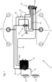
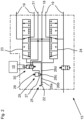
- the 1 and 2 show both the prior art and the invention, depending on the configuration of an electronic control unit 10 in an air spring system 11.
- control unit 10 for a trailer vehicle with a pneumatic brake system and three axles is shown. Brake system and axles are not shown in detail.
- a pressure sensor for detecting the pressure in reservoir 13 of the brake system.
- speed sensors from whose signals control unit 10 can determine the speed.
- control unit 10 can receive a speed signal from a towing vehicle via a line (not shown).
- Storage pressure from the storage tank 12 is provided via the pneumatic lines 18 .
- the air spring bellows 16 , 17 are connected to the RtR valve 15 via the pneumatic lines 19 and indirectly to the air spring valve 14 .
- a linkage 21 is shown for this purpose, which is connected on the one hand to the air spring valve 14 and a height sensor integrated therein and on the other hand to an axle (not shown) or another part of a chassis.
- the RtR valve 15 an operator can manually aerate or vent the air spring bellows 16, 17 in a known manner and thus raise or lower a vehicle body relative to the chassis.
- the RtR valve 15 is designed internally so that an in 1 shown adjusting lever 22 can be moved into a "lower” position and engage there. The operator can release the control lever 22 in the "lower” position, while the air spring bellows 16, 17 continue to be deflated until the vehicle body is completely lowered, for example for rail transport of the trailer vehicle. This applies analogously to a "raise" position of the adjusting lever 22.
- control lever 22 is in a driving position. Between the driving position and the "lower” position, the actuating lever 22 can still assume a stop position, in which the previously lowered position of the vehicle body is maintained, with the air spring valve 14 still blocked. This applies analogously to a stop position between the driving position and the "lift” position ".
- the control unit 10 monitors the speed of the trailer vehicle and, when a previously defined minimum speed is reached, sends an electrical pulse E via the output 20a and the line 20 to the RtR valve 15, which then returns to the driving position.
- the RtR valve 15 has, in a known manner, separate multi-way valves 23, 24 for the air spring bellows 16, 17, in this case 4/5-way valves. These are adjusted by the adjusting lever 22.
- a component of an adjustment mechanism 25 connected to the adjusting lever 22 is a latching device 29 with a latching element 27 entering latching grooves 26a, 26b, 26c, 26d. 26b, 26c, 26d can be raised out so that unlocking takes place.
- the latching device 29 can be actuated pneumatically via a solenoid valve 30 .
- the solenoid valve 30 receives from the control unit 10 the electrical pulse already mentioned above when the minimum speed is exceeded.
- the latching device 29 can be optionally connected to the line 18 carrying the reservoir pressure or to a vent 31 by adjusting the solenoid valve 30 . As soon as reservoir pressure is present, the latching device 29 is unlocked, and the latching device 29 is effective when connected to the vent 31 .
- the function of the locking device 29 with pneumatic unlocking of the locking element 27 is also in the DE 10 2010 011 433 A1 , there 3 with associated description. Reference is also made thereto for a better understanding and for optional supplementation of the disclosure.
- the control lever 22 is in the driving position, also in 1 .
- the latching element 27 lies in a latching groove 26c belonging to the driving position.
- left and right are adjacent in 2 the locking grooves 26b, 26d for stop positions are shown, the locking groove 26a for the “lowering” position on the far left, just like in FIG 1 the EP 3 643 543 B1 .
- a locking groove for the "raise” position is not shown, but can be provided.
- control unit 10 controls the triggering of the RtR valve 15 in a special way: In addition to the speed, control unit 10 checks the reservoir pressure in reservoir 13 for the brake system. When the reservoirs 12, 13 are completely empty, they are refilled one after the other via a supply line from the towing vehicle. Courses of the reservoir pressures are in 3 shown. For safety reasons, the reservoir 13 for the brake system is filled first, see curve B fine dashed curve L. After a certain time, here after about 70 seconds from the beginning of the filling of the reservoir 13, the pressures in the two reservoirs 12, 13 increase and become almost the same until the full pressure of 7.5 bar or one is reached similar pressure.
- the locking device 29 is unlocked with the aid of the pressure in the reservoir 12 of the air spring system.
- control unit 10 emits electrical pulse E several times until the reservoir pressure in reservoir 13 of the brake system exceeds a limit value PG.
- the limit value PG is calculated from the overflow pressure PÜ plus a pressure difference dP.
- the pressure difference dP is preferably 0.5 bar, but can also deviate from this value up or down and is preferably 0.5 bar between 0.2 bar and 1.3 bar.
- a time limit or change in the overflow pressure PÜ is not intended to be shown.
- the electrical pulse E can be controlled repeatedly and with a time limit, see 4 .
- the solid line v indicates the speed of the trailer vehicle, while the dashed line E represents the electrical pulses. According to 4 four electrical pulses E are triggered one after the other from the beginning of the minimum speed of 30 km/h and with small pauses between the electrical pulses E.
- Pulse spacing a and pulse duration d are in figure 5 shown.
- the pulse interval is preferably 15 seconds as the period between the start of two consecutive pulses E, with a pulse duration of 5 seconds. Accordingly, the breaks are 10 seconds each.
- the last pulse E is triggered as long as the pressure B has not yet exceeded the limit value PG, in the example the 4 at about 85 seconds after the beginning of the filling of the reservoirs 12, 13. As soon as the limit value PG is exceeded, no further pulse E is triggered.
- the first controlled electrical pulse E can be maintained until the limit value PG is exceeded.
- the electrical pulse E is only triggered when the limit value PG is exceeded, again in connection with the exceeding of the minimum speed.
Landscapes
- Engineering & Computer Science (AREA)
- Mechanical Engineering (AREA)
- Vehicle Body Suspensions (AREA)
Applications Claiming Priority (1)
| Application Number | Priority Date | Filing Date | Title |
|---|---|---|---|
| DE102022100288.8A DE102022100288A1 (de) | 2022-01-07 | 2022-01-07 | Verfahren zum Auslösen eines RtR-Ventils, Steuergerät, Luftfedersystem und Anhängefahrzeug |
Publications (2)
| Publication Number | Publication Date |
|---|---|
| EP4209367A1 true EP4209367A1 (fr) | 2023-07-12 |
| EP4209367B1 EP4209367B1 (fr) | 2024-08-21 |
Family
ID=84439826
Family Applications (1)
| Application Number | Title | Priority Date | Filing Date |
|---|---|---|---|
| EP22211841.6A Active EP4209367B1 (fr) | 2022-01-07 | 2022-12-07 | Procédé de déclenchement d'une soupape rtr, appareil de commande, système d'air comprimé et remorque |
Country Status (2)
| Country | Link |
|---|---|
| EP (1) | EP4209367B1 (fr) |
| DE (1) | DE102022100288A1 (fr) |
Citations (2)
| Publication number | Priority date | Publication date | Assignee | Title |
|---|---|---|---|---|
| DE102010011433A1 (de) | 2009-12-23 | 2011-06-30 | WABCO GmbH, 30453 | Ventileinrichtung für eine Luftfederungsanlage |
| EP3643543B1 (fr) | 2018-10-26 | 2021-06-30 | ZF CV Systems Europe BV | Double solénoïde dans un dispositif de commande de suspension à air de remorque |
Family Cites Families (7)
| Publication number | Priority date | Publication date | Assignee | Title |
|---|---|---|---|---|
| DE4202729C2 (de) | 1991-06-24 | 1993-11-25 | Grau Gmbh | Steueranlage zum willkürlichen Heben und Senken des Fahrzeugaufbaus von luftgefederten Fahrzeugen |
| DE102005019479B3 (de) | 2005-04-27 | 2007-01-18 | Haldex Brake Products Gmbh | Anhängerbremsventil für einen Kraftfahrzeug-Anhänger |
| DE102007045012A1 (de) | 2007-09-20 | 2009-04-02 | Wabco Gmbh | Ventileinrichtung für eine Luftfederungsanlage |
| EP2263892A1 (fr) | 2009-06-10 | 2010-12-22 | Haldex Brake Products GmbH | Unité de vanne de commande destinée à aérer et ventiler des soufflets à ressort d'un véhicule ou d'une remorque |
| DE102010010605B4 (de) | 2010-03-08 | 2014-01-02 | Knorr-Bremse Systeme für Nutzfahrzeuge GmbH | Vorrichtung zur Steuerung von pneumatischen Einrichtungen eines Anhängers |
| DE102017118529B4 (de) | 2017-08-14 | 2019-05-29 | Haldex Brake Products Aktiebolag | Elektronisch gesteuerte Anhänger-Bremssteuereinheit und Anhänger-Bremsanlage |
| US10850721B2 (en) | 2018-03-30 | 2020-12-01 | Bendix Commercial Vehicle Systems Llc | System and method for filling a trailer reservoir |
-
2022
- 2022-01-07 DE DE102022100288.8A patent/DE102022100288A1/de active Pending
- 2022-12-07 EP EP22211841.6A patent/EP4209367B1/fr active Active
Patent Citations (2)
| Publication number | Priority date | Publication date | Assignee | Title |
|---|---|---|---|---|
| DE102010011433A1 (de) | 2009-12-23 | 2011-06-30 | WABCO GmbH, 30453 | Ventileinrichtung für eine Luftfederungsanlage |
| EP3643543B1 (fr) | 2018-10-26 | 2021-06-30 | ZF CV Systems Europe BV | Double solénoïde dans un dispositif de commande de suspension à air de remorque |
Also Published As
| Publication number | Publication date |
|---|---|
| EP4209367B1 (fr) | 2024-08-21 |
| DE102022100288A1 (de) | 2023-07-13 |
Similar Documents
| Publication | Publication Date | Title |
|---|---|---|
| EP3129264B1 (fr) | Dispositif de commande électropneumatique de frein de stationnement | |
| EP3678909B1 (fr) | Dispositif electropneumatique de commande de frein de stationnement et systeme de freinage de vehicule | |
| EP3341253B1 (fr) | Frein de parquage électrique avec source auxiliaire d'énergie | |
| EP2125398B1 (fr) | Système de suspension pneumatique pourvu de soupapes de commande actionnées exclusivement par un fluide sous pression | |
| DE102007008159B4 (de) | Luftfederungseinrichtung mit elektrisch betätigtem Sperrventil | |
| EP1651491B1 (fr) | Dispositif de réalimentation de circuits de freinage après une consommation importante d'air comprimé et dispositif pour mettre en oeuvre ce procédé | |
| DE102008021818B4 (de) | Verfahren zum Steuern einer Niveauregelanlage sowie Niveauregelanlage | |
| DE102009005229C5 (de) | Luftfederanlage mit Höhenbegrenzung | |
| DE69014487T2 (de) | Druckluftbremsanlage. | |
| DE102008047801B3 (de) | Vorrichtung zur Steuerung von pneumatischen Einrichtungen eines Anhängers | |
| EP4209367B1 (fr) | Procédé de déclenchement d'une soupape rtr, appareil de commande, système d'air comprimé et remorque | |
| DE102010010605B4 (de) | Vorrichtung zur Steuerung von pneumatischen Einrichtungen eines Anhängers | |
| DE1192229B (de) | Elektropneumatische Fuehrerbremsventil-einrichtung, insbesondere fuer Schienenfahrzeuge | |
| DE2113204C3 (de) | Indirekt wirkende, lastabhängige Druckluftbremse, insbesondere für Schienenfahrzeuge | |
| DE3636139C2 (de) | Bremszylinderdruckregler für Druckluftbremsen von Fahrzeugen | |
| EP0215206B1 (fr) | Installation de freinage de conducteur électro-pneumatique pour véhicules ferroviaires | |
| DE102013008655B4 (de) | Verfahren zur Niveauregelung eines luftgefederten Kraftfahrzeugs | |
| DE4013670A1 (de) | Omnibus, insbesondere niederflurbus | |
| DE3545222A1 (de) | Anfahrhilfe fuer luftgefederte kraftfahrzeuge | |
| EP0017260A1 (fr) | Accélérateur pour frein à action rapide | |
| DE19845925C1 (de) | Steueranlage für ein luftgefedertes Fahrzeug mit Niveauregelung | |
| EP2179872B1 (fr) | Système de suspension pneumatique avec un mécanisme de commande électromécanique pour repositionner un distributeur de commande dans la position de roulage | |
| EP1067033B1 (fr) | Procédé de désserrage de frein d'un système de freinage à air comprimé au moyen d'un choc de pression | |
| DE102018130681A1 (de) | Verfahren zur Erkennung und Quantifizierung einer selbsthaltenden Eigenschaft eines Aktors, vorzugsweise eines Kupplungsaktors | |
| EP1800984B1 (fr) | Procédé de réalimentation de circuits de freinage après une consommation importante d'air comprimé |
Legal Events
| Date | Code | Title | Description |
|---|---|---|---|
| PUAI | Public reference made under article 153(3) epc to a published international application that has entered the european phase |
Free format text: ORIGINAL CODE: 0009012 |
|
| STAA | Information on the status of an ep patent application or granted ep patent |
Free format text: STATUS: THE APPLICATION HAS BEEN PUBLISHED |
|
| AK | Designated contracting states |
Kind code of ref document: A1 Designated state(s): AL AT BE BG CH CY CZ DE DK EE ES FI FR GB GR HR HU IE IS IT LI LT LU LV MC ME MK MT NL NO PL PT RO RS SE SI SK SM TR |
|
| STAA | Information on the status of an ep patent application or granted ep patent |
Free format text: STATUS: REQUEST FOR EXAMINATION WAS MADE |
|
| 17P | Request for examination filed |
Effective date: 20230724 |
|
| RBV | Designated contracting states (corrected) |
Designated state(s): AL AT BE BG CH CY CZ DE DK EE ES FI FR GB GR HR HU IE IS IT LI LT LU LV MC ME MK MT NL NO PL PT RO RS SE SI SK SM TR |
|
| GRAP | Despatch of communication of intention to grant a patent |
Free format text: ORIGINAL CODE: EPIDOSNIGR1 |
|
| STAA | Information on the status of an ep patent application or granted ep patent |
Free format text: STATUS: GRANT OF PATENT IS INTENDED |
|
| INTG | Intention to grant announced |
Effective date: 20240126 |
|
| GRAJ | Information related to disapproval of communication of intention to grant by the applicant or resumption of examination proceedings by the epo deleted |
Free format text: ORIGINAL CODE: EPIDOSDIGR1 |
|
| STAA | Information on the status of an ep patent application or granted ep patent |
Free format text: STATUS: REQUEST FOR EXAMINATION WAS MADE |
|
| INTC | Intention to grant announced (deleted) | ||
| GRAP | Despatch of communication of intention to grant a patent |
Free format text: ORIGINAL CODE: EPIDOSNIGR1 |
|
| STAA | Information on the status of an ep patent application or granted ep patent |
Free format text: STATUS: GRANT OF PATENT IS INTENDED |
|
| GRAJ | Information related to disapproval of communication of intention to grant by the applicant or resumption of examination proceedings by the epo deleted |
Free format text: ORIGINAL CODE: EPIDOSDIGR1 |
|
| STAA | Information on the status of an ep patent application or granted ep patent |
Free format text: STATUS: REQUEST FOR EXAMINATION WAS MADE |
|
| INTG | Intention to grant announced |
Effective date: 20240429 |
|
| GRAP | Despatch of communication of intention to grant a patent |
Free format text: ORIGINAL CODE: EPIDOSNIGR1 |
|
| STAA | Information on the status of an ep patent application or granted ep patent |
Free format text: STATUS: GRANT OF PATENT IS INTENDED |
|
| INTC | Intention to grant announced (deleted) | ||
| INTG | Intention to grant announced |
Effective date: 20240603 |
|
| GRAS | Grant fee paid |
Free format text: ORIGINAL CODE: EPIDOSNIGR3 |
|
| GRAA | (expected) grant |
Free format text: ORIGINAL CODE: 0009210 |
|
| STAA | Information on the status of an ep patent application or granted ep patent |
Free format text: STATUS: THE PATENT HAS BEEN GRANTED |
|
| AK | Designated contracting states |
Kind code of ref document: B1 Designated state(s): AL AT BE BG CH CY CZ DE DK EE ES FI FR GB GR HR HU IE IS IT LI LT LU LV MC ME MK MT NL NO PL PT RO RS SE SI SK SM TR |
|
| REG | Reference to a national code |
Ref country code: GB Ref legal event code: FG4D Free format text: NOT ENGLISH |
|
| REG | Reference to a national code |
Ref country code: CH Ref legal event code: EP |
|
| REG | Reference to a national code |
Ref country code: DE Ref legal event code: R096 Ref document number: 502022001514 Country of ref document: DE |
|
| REG | Reference to a national code |
Ref country code: IE Ref legal event code: FG4D Free format text: LANGUAGE OF EP DOCUMENT: GERMAN |
|
| REG | Reference to a national code |
Ref country code: LT Ref legal event code: MG9D |
|
| REG | Reference to a national code |
Ref country code: NL Ref legal event code: MP Effective date: 20240821 |
|
| PG25 | Lapsed in a contracting state [announced via postgrant information from national office to epo] |
Ref country code: NO Free format text: LAPSE BECAUSE OF FAILURE TO SUBMIT A TRANSLATION OF THE DESCRIPTION OR TO PAY THE FEE WITHIN THE PRESCRIBED TIME-LIMIT Effective date: 20241121 |
|
| PG25 | Lapsed in a contracting state [announced via postgrant information from national office to epo] |
Ref country code: PT Free format text: LAPSE BECAUSE OF FAILURE TO SUBMIT A TRANSLATION OF THE DESCRIPTION OR TO PAY THE FEE WITHIN THE PRESCRIBED TIME-LIMIT Effective date: 20241223 Ref country code: PL Free format text: LAPSE BECAUSE OF FAILURE TO SUBMIT A TRANSLATION OF THE DESCRIPTION OR TO PAY THE FEE WITHIN THE PRESCRIBED TIME-LIMIT Effective date: 20240821 Ref country code: GR Free format text: LAPSE BECAUSE OF FAILURE TO SUBMIT A TRANSLATION OF THE DESCRIPTION OR TO PAY THE FEE WITHIN THE PRESCRIBED TIME-LIMIT Effective date: 20241122 Ref country code: FI Free format text: LAPSE BECAUSE OF FAILURE TO SUBMIT A TRANSLATION OF THE DESCRIPTION OR TO PAY THE FEE WITHIN THE PRESCRIBED TIME-LIMIT Effective date: 20240821 Ref country code: NL Free format text: LAPSE BECAUSE OF FAILURE TO SUBMIT A TRANSLATION OF THE DESCRIPTION OR TO PAY THE FEE WITHIN THE PRESCRIBED TIME-LIMIT Effective date: 20240821 |
|
| PG25 | Lapsed in a contracting state [announced via postgrant information from national office to epo] |
Ref country code: BG Free format text: LAPSE BECAUSE OF FAILURE TO SUBMIT A TRANSLATION OF THE DESCRIPTION OR TO PAY THE FEE WITHIN THE PRESCRIBED TIME-LIMIT Effective date: 20240821 |
|
| PG25 | Lapsed in a contracting state [announced via postgrant information from national office to epo] |
Ref country code: LV Free format text: LAPSE BECAUSE OF FAILURE TO SUBMIT A TRANSLATION OF THE DESCRIPTION OR TO PAY THE FEE WITHIN THE PRESCRIBED TIME-LIMIT Effective date: 20240821 |
|
| PG25 | Lapsed in a contracting state [announced via postgrant information from national office to epo] |
Ref country code: IS Free format text: LAPSE BECAUSE OF FAILURE TO SUBMIT A TRANSLATION OF THE DESCRIPTION OR TO PAY THE FEE WITHIN THE PRESCRIBED TIME-LIMIT Effective date: 20241221 |
|
| PG25 | Lapsed in a contracting state [announced via postgrant information from national office to epo] |
Ref country code: HR Free format text: LAPSE BECAUSE OF FAILURE TO SUBMIT A TRANSLATION OF THE DESCRIPTION OR TO PAY THE FEE WITHIN THE PRESCRIBED TIME-LIMIT Effective date: 20240821 |
|
| PG25 | Lapsed in a contracting state [announced via postgrant information from national office to epo] |
Ref country code: ES Free format text: LAPSE BECAUSE OF FAILURE TO SUBMIT A TRANSLATION OF THE DESCRIPTION OR TO PAY THE FEE WITHIN THE PRESCRIBED TIME-LIMIT Effective date: 20240821 Ref country code: RS Free format text: LAPSE BECAUSE OF FAILURE TO SUBMIT A TRANSLATION OF THE DESCRIPTION OR TO PAY THE FEE WITHIN THE PRESCRIBED TIME-LIMIT Effective date: 20241121 |
|
| PG25 | Lapsed in a contracting state [announced via postgrant information from national office to epo] |
Ref country code: RS Free format text: LAPSE BECAUSE OF FAILURE TO SUBMIT A TRANSLATION OF THE DESCRIPTION OR TO PAY THE FEE WITHIN THE PRESCRIBED TIME-LIMIT Effective date: 20241121 Ref country code: PT Free format text: LAPSE BECAUSE OF FAILURE TO SUBMIT A TRANSLATION OF THE DESCRIPTION OR TO PAY THE FEE WITHIN THE PRESCRIBED TIME-LIMIT Effective date: 20241223 Ref country code: PL Free format text: LAPSE BECAUSE OF FAILURE TO SUBMIT A TRANSLATION OF THE DESCRIPTION OR TO PAY THE FEE WITHIN THE PRESCRIBED TIME-LIMIT Effective date: 20240821 Ref country code: NO Free format text: LAPSE BECAUSE OF FAILURE TO SUBMIT A TRANSLATION OF THE DESCRIPTION OR TO PAY THE FEE WITHIN THE PRESCRIBED TIME-LIMIT Effective date: 20241121 Ref country code: NL Free format text: LAPSE BECAUSE OF FAILURE TO SUBMIT A TRANSLATION OF THE DESCRIPTION OR TO PAY THE FEE WITHIN THE PRESCRIBED TIME-LIMIT Effective date: 20240821 Ref country code: LV Free format text: LAPSE BECAUSE OF FAILURE TO SUBMIT A TRANSLATION OF THE DESCRIPTION OR TO PAY THE FEE WITHIN THE PRESCRIBED TIME-LIMIT Effective date: 20240821 Ref country code: IS Free format text: LAPSE BECAUSE OF FAILURE TO SUBMIT A TRANSLATION OF THE DESCRIPTION OR TO PAY THE FEE WITHIN THE PRESCRIBED TIME-LIMIT Effective date: 20241221 Ref country code: HR Free format text: LAPSE BECAUSE OF FAILURE TO SUBMIT A TRANSLATION OF THE DESCRIPTION OR TO PAY THE FEE WITHIN THE PRESCRIBED TIME-LIMIT Effective date: 20240821 Ref country code: GR Free format text: LAPSE BECAUSE OF FAILURE TO SUBMIT A TRANSLATION OF THE DESCRIPTION OR TO PAY THE FEE WITHIN THE PRESCRIBED TIME-LIMIT Effective date: 20241122 Ref country code: FI Free format text: LAPSE BECAUSE OF FAILURE TO SUBMIT A TRANSLATION OF THE DESCRIPTION OR TO PAY THE FEE WITHIN THE PRESCRIBED TIME-LIMIT Effective date: 20240821 Ref country code: ES Free format text: LAPSE BECAUSE OF FAILURE TO SUBMIT A TRANSLATION OF THE DESCRIPTION OR TO PAY THE FEE WITHIN THE PRESCRIBED TIME-LIMIT Effective date: 20240821 Ref country code: BG Free format text: LAPSE BECAUSE OF FAILURE TO SUBMIT A TRANSLATION OF THE DESCRIPTION OR TO PAY THE FEE WITHIN THE PRESCRIBED TIME-LIMIT Effective date: 20240821 |
|
| PG25 | Lapsed in a contracting state [announced via postgrant information from national office to epo] |
Ref country code: SM Free format text: LAPSE BECAUSE OF FAILURE TO SUBMIT A TRANSLATION OF THE DESCRIPTION OR TO PAY THE FEE WITHIN THE PRESCRIBED TIME-LIMIT Effective date: 20240821 Ref country code: DK Free format text: LAPSE BECAUSE OF FAILURE TO SUBMIT A TRANSLATION OF THE DESCRIPTION OR TO PAY THE FEE WITHIN THE PRESCRIBED TIME-LIMIT Effective date: 20240821 Ref country code: RO Free format text: LAPSE BECAUSE OF FAILURE TO SUBMIT A TRANSLATION OF THE DESCRIPTION OR TO PAY THE FEE WITHIN THE PRESCRIBED TIME-LIMIT Effective date: 20240821 |
|
| PG25 | Lapsed in a contracting state [announced via postgrant information from national office to epo] |
Ref country code: EE Free format text: LAPSE BECAUSE OF FAILURE TO SUBMIT A TRANSLATION OF THE DESCRIPTION OR TO PAY THE FEE WITHIN THE PRESCRIBED TIME-LIMIT Effective date: 20240821 |
|
| PG25 | Lapsed in a contracting state [announced via postgrant information from national office to epo] |
Ref country code: CZ Free format text: LAPSE BECAUSE OF FAILURE TO SUBMIT A TRANSLATION OF THE DESCRIPTION OR TO PAY THE FEE WITHIN THE PRESCRIBED TIME-LIMIT Effective date: 20240821 |
|
| PG25 | Lapsed in a contracting state [announced via postgrant information from national office to epo] |
Ref country code: IT Free format text: LAPSE BECAUSE OF FAILURE TO SUBMIT A TRANSLATION OF THE DESCRIPTION OR TO PAY THE FEE WITHIN THE PRESCRIBED TIME-LIMIT Effective date: 20240821 Ref country code: SK Free format text: LAPSE BECAUSE OF FAILURE TO SUBMIT A TRANSLATION OF THE DESCRIPTION OR TO PAY THE FEE WITHIN THE PRESCRIBED TIME-LIMIT Effective date: 20240821 |
|
| REG | Reference to a national code |
Ref country code: DE Ref legal event code: R026 Ref document number: 502022001514 Country of ref document: DE |
|
| PLBI | Opposition filed |
Free format text: ORIGINAL CODE: 0009260 |
|
| PLAX | Notice of opposition and request to file observation + time limit sent |
Free format text: ORIGINAL CODE: EPIDOSNOBS2 |
|
| 26 | Opposition filed |
Opponent name: KNORR-BREMSESYSTEME FUER NUTZFAHRZEUGE GMBH Effective date: 20250520 |
|
| PG25 | Lapsed in a contracting state [announced via postgrant information from national office to epo] |
Ref country code: MC Free format text: LAPSE BECAUSE OF FAILURE TO SUBMIT A TRANSLATION OF THE DESCRIPTION OR TO PAY THE FEE WITHIN THE PRESCRIBED TIME-LIMIT Effective date: 20240821 |
|
| PG25 | Lapsed in a contracting state [announced via postgrant information from national office to epo] |
Ref country code: LU Free format text: LAPSE BECAUSE OF NON-PAYMENT OF DUE FEES Effective date: 20241207 |
|
| PG25 | Lapsed in a contracting state [announced via postgrant information from national office to epo] |
Ref country code: SE Free format text: LAPSE BECAUSE OF FAILURE TO SUBMIT A TRANSLATION OF THE DESCRIPTION OR TO PAY THE FEE WITHIN THE PRESCRIBED TIME-LIMIT Effective date: 20240821 |
|
| PLBB | Reply of patent proprietor to notice(s) of opposition received |
Free format text: ORIGINAL CODE: EPIDOSNOBS3 |
|
| REG | Reference to a national code |
Ref country code: BE Ref legal event code: MM Effective date: 20241231 |
|
| PG25 | Lapsed in a contracting state [announced via postgrant information from national office to epo] |
Ref country code: BE Free format text: LAPSE BECAUSE OF NON-PAYMENT OF DUE FEES Effective date: 20241231 |
|
| PGFP | Annual fee paid to national office [announced via postgrant information from national office to epo] |
Ref country code: FR Payment date: 20250930 Year of fee payment: 4 |
|
| PG25 | Lapsed in a contracting state [announced via postgrant information from national office to epo] |
Ref country code: IE Free format text: LAPSE BECAUSE OF NON-PAYMENT OF DUE FEES Effective date: 20241207 |
|
| PGFP | Annual fee paid to national office [announced via postgrant information from national office to epo] |
Ref country code: DE Payment date: 20250930 Year of fee payment: 4 |
|
| PGFP | Annual fee paid to national office [announced via postgrant information from national office to epo] |
Ref country code: AT Payment date: 20260113 Year of fee payment: 4 |
|
| PG25 | Lapsed in a contracting state [announced via postgrant information from national office to epo] |
Ref country code: CY Free format text: LAPSE BECAUSE OF FAILURE TO SUBMIT A TRANSLATION OF THE DESCRIPTION OR TO PAY THE FEE WITHIN THE PRESCRIBED TIME-LIMIT; INVALID AB INITIO Effective date: 20221207 |