EP4209403B1 - Dispositif d'étalonnage permettant d'étalonner au moins un capteur d'angle de pivotement ou un capteur d'angle de braquage - Google Patents
Dispositif d'étalonnage permettant d'étalonner au moins un capteur d'angle de pivotement ou un capteur d'angle de braquage Download PDFInfo
- Publication number
- EP4209403B1 EP4209403B1 EP22150511.8A EP22150511A EP4209403B1 EP 4209403 B1 EP4209403 B1 EP 4209403B1 EP 22150511 A EP22150511 A EP 22150511A EP 4209403 B1 EP4209403 B1 EP 4209403B1
- Authority
- EP
- European Patent Office
- Prior art keywords
- segment
- calibration device
- straight
- road vehicle
- angle sensor
- Prior art date
- Legal status (The legal status is an assumption and is not a legal conclusion. Google has not performed a legal analysis and makes no representation as to the accuracy of the status listed.)
- Active
Links
Images
Classifications
-
- G—PHYSICS
- G01—MEASURING; TESTING
- G01D—MEASURING NOT SPECIALLY ADAPTED FOR A SPECIFIC VARIABLE; ARRANGEMENTS FOR MEASURING TWO OR MORE VARIABLES NOT COVERED IN A SINGLE OTHER SUBCLASS; TARIFF METERING APPARATUS; MEASURING OR TESTING NOT OTHERWISE PROVIDED FOR
- G01D18/00—Testing or calibrating apparatus or arrangements provided for in groups G01D1/00 - G01D15/00
-
- G—PHYSICS
- G01—MEASURING; TESTING
- G01M—TESTING STATIC OR DYNAMIC BALANCE OF MACHINES OR STRUCTURES; TESTING OF STRUCTURES OR APPARATUS, NOT OTHERWISE PROVIDED FOR
- G01M17/00—Testing of vehicles
- G01M17/007—Wheeled or endless-tracked vehicles
- G01M17/06—Steering behaviour; Rolling behaviour
-
- B—PERFORMING OPERATIONS; TRANSPORTING
- B62—LAND VEHICLES FOR TRAVELLING OTHERWISE THAN ON RAILS
- B62D—MOTOR VEHICLES; TRAILERS
- B62D53/00—Tractor-trailer combinations; Road trains
Definitions
- the present invention relates to a calibration device and a method for calibrating at least one articulation angle sensor or a steering angle sensor of a multi-part road vehicle.
- the present invention also relates to a system with such a calibration device and a multi-part road vehicle.
- Multi-part road vehicles in the form of articulated buses in particular push-articulated buses, are known from the prior art, in which a two- or three-axle front vehicle is connected to a rear vehicle via a joint with bellows.
- the engine and drive can be located in either the front or the rear of the vehicle.
- multi-part road vehicles usually have an articulation angle sensor for each joint between the cars.
- the articulation angle sensor measures the angle included between the longitudinal axes of two coupled wagons while driving.
- the measurement signal from the articulation angle sensor is used for active intervention in the control of the vehicle.
- the articulation angle can, on the one hand, influence the articulation angle damping of the joint, but can also be used to adjust the engine power or actively brake the vehicle.
- the calibration of the articulation angle sensor after system integration i.e. after connecting the vehicle's carriages to the joint, is carried out on a large, traffic-free and obstacle-free commissioning area.
- the vehicle drives straight ahead at walking speed. A person walks behind the vehicle and takes aim along one side of the vehicle to estimate which car needs to be steered in which direction so that all vehicle segments are positioned exactly one behind the other in the longitudinal direction. Once this has happened, the vehicle stops with the articulation angle sensor to be calibrated, the current measurement signal from the articulation angle sensor is read out and marked as the zero position in the joint or vehicle control.
- each steerable wheel is moved onto a turntable, on which a steering angle of the wheel can be read in relation to the straight-ahead direction of the vehicle or the respective car on which the wheel is arranged.
- the wheels are manually steered into their mechanical steering stops and the associated swivel angles of the turntables are read. These pivot angles are then assigned to the current measurement signals from the steering angle sensors and stored in the vehicle control system.
- a conventional wheel alignment system (laser protractor) is mounted on the rims of the vehicle and the wheels are adjusted so that the wheel alignment system confirms the parallelism to the longitudinal axis of the vehicle.
- the associated measurement signals from the steering angle sensors are read and stored as the straight-ahead position in the vehicle control system.
- the straight-ahead position of the wheels is also determined while driving slowly.
- the axles are steered manually or automatically in such a way that the straight-ahead position of the coupled cars determined when the articulation angle sensors are calibrated is adopted and maintained.
- DE102014102302 A1 describes a method for calibrating a towed or self-propelled commercial vehicle with at least one steerable axle or a combination of a self-propelled towing vehicle and a towed vehicle with at least one steerable axle.
- the positions of the end stops for straight-ahead travel are calibrated, with the end stops of the steerable axle of the commercial vehicle being automatically approached when the commercial vehicle is at a standstill and the positions of these end stops being automatically determined for calibration.
- a provisional position for straight-ahead travel of the respective steerable axle is automatically determined from the positions of the end stops by averaging.
- a final position for the straight-ahead travel of the axle is determined automatically because it is enabled in such a way that it tracks passively during straight-ahead travel.
- DE102017203426 A1 relates to a calibration base for calibrating driver assistance systems. This is designed with a homogeneous positioning pattern made of grids or points, which enables two measuring devices arranged on the calibration floor to clearly determine their position on the calibration floor based on the positioning pattern.
- the measuring device works by recording images
- the present invention is based on the object of providing a calibration device and a method for calibrating at least one articulation angle sensor or a steering angle sensor of a multi-part road vehicle, which enable simplified calibration, in particular of more complex multi-part road vehicles, for example trackless trams with several axles.
- the calibration device for calibrating at least one articulation angle sensor or a steering angle sensor of a multi-part road vehicle according to the attached independent claim 1.
- the calibration device has at least one first alignment aid, the first alignment aid extending straight in a longitudinal direction.
- the first alignment aid is designed in such a way that wheels of at least one axle of a first car of the multi-part road vehicle and wheels of an axle, but preferably two axles, of a second car of the multi-part road vehicle can be moved onto it in such a way that the first and second cars are then in are aligned with a straight ahead position.
- the calibration device has at least a first pivotable segment, wherein the first pivotable segment is arranged at a first position in the longitudinal direction of the first alignment aid.
- the first pivotable segment can be pivoted about a pivot axis from a straight-ahead position into a steered position, so that a steerable wheel of an axle of the road vehicle can be pivoted with the first segment.
- the aforementioned object is also achieved by a system with a calibration device, as described in embodiments hereinafter, and with a multi-part road vehicle.
- the multi-part road vehicle has a plurality of movably connected cars and a plurality of axles with wheels with tires.
- the calibration device provides a calibration gauge onto which the multi-part road vehicle is mounted, the first alignment aid defining the straight, aligned arrangement of the individual cars of the road vehicle. After driving onto the alignment aid, the vehicle's carriages are by definition straight, so that all carriages are positioned exactly in a line one behind the other. The articulation angles are in the straight-ahead position and the steering angles are in the zero position.
- the joints and thus the articulation angle sensors are typically pre-calibrated on a test stand before installation in the vehicle, so that after the system has been integrated into the vehicle, only the straight-ahead position needs to be adjusted. It is therefore sufficient to provide a gauge for the articulation angle sensors that defines the straight, aligned arrangement of the cars one behind the other.
- Calibration with the calibration device according to the invention is clearly reproducible and can also be used for service and maintenance purposes. Calibration trips on test sites as well as the installation and removal of calibration aids such as wheel alignment accessories are no longer necessary.
- the calibration device can be set up at the end of a production line and has a maximum space requirement of one vehicle length. Individual errors by the operating personnel when assessing the correct straight-ahead position and zero position are reduced or avoided. The personnel and time expenditure is significantly reduced.
- the straight-ahead position in the sense of the present application refers to the position of the pivotable segments, which, when transmitted to the wheels of the pivotable axle, causes the vehicle to travel straight ahead.
- the calibration device additionally has a second alignment aid.
- the first alignment aid and the second alignment aid extend straight in the longitudinal direction and parallel to one another, with the first alignment aid and the second alignment aid being arranged at a track distance from one another.
- the first and/or second alignment aid is selected from a line painted or projected onto a drivable surface, a web projecting relative to a surface, a recess embedded in a surface and a rail track or a combination thereof.
- a combination of these realizations of the first or second alignment aid can be realized, for example, in that the first alignment aid is a rail track and the second alignment aid is a line painted on a surface that can be driven on.
- a combination can also be realized in that, for example, the first alignment aid has a section in the longitudinal direction that is realized as a painted line and a section that is designed as a rail track.
- first or the second alignment aid is a first or second rail track
- first and/or the second segment is a first or second rail segment.
- the length of at least the first or second alignment aid in the longitudinal direction is at least so large that all the wheels of the road vehicle to be calibrated fit on it.
- the calibration device has a pair of the first pivotable segment and a second pivotable segment, wherein the second pivotable segment is arranged at the first position in the longitudinal direction, and wherein the second pivotable segment is pivotable from a straight ahead position to a steered position is so that the steerable wheels of the axle of the road vehicle are pivotable with the first and second segments.
- the steering angle sensors of both wheels on an axle can be calibrated independently of one another. Such a separate calibration of both wheels on an axle can be advantageous both when the two wheels are mechanically coupled via a steering linkage and when the steering systems of the two wheels on an axle are designed as individual wheel steering systems.
- an average value of the two steering angle sensors is used for calibration.
- the multi-part road vehicle is driven onto the calibration device in such a way that a wheel of a steerable axle is arranged on the first pivotable segment of a pair and preferably the second wheel of this axle is arranged on the second pivotable segment of the same pair of first and second pivotable segments.
- One or more steering angle sensors of this axle can then be calibrated by actively or passively turning the steerable wheels of this axle.
- the first and optionally the second pivotable segment are each constructed in the manner of a turntable. While it is possible to design the segment to be pivotable about a rigid axis, which is essentially perpendicular to the plane spanned by the first alignment aid and the second alignment aid, an embodiment of the invention is preferred in which the first and second pivotable segments respectively are floating, so that when the wheels turn, for example, the camber occurs of the wheels, but also the fact that the pivot axis typically does not go through the contact point of the wheels.
- the multi-part road vehicle has a plurality of steered axles, the plurality of steered axles preferably being arranged on at least a first and a second car.
- a design of a multi-part road vehicle corresponds to the typical construction of a trackless tram.
- the multi-part road vehicle has a plurality of steering angle sensors on a plurality of axles. In a further embodiment, the multi-part road vehicle has a plurality of cars, with an articulation angle sensor for detecting the articulation angle between these two cars being arranged between each two cars.
- Such vehicles are also known as “trackless trams” and replace rail-bound train systems with high-capacity road vehicles that either drive on their own roads or on public roads. Due to their length, these vehicles must have a plurality of steered axles.
- the calibration device can also be used for conventional vehicles with two cars and a steered axle
- the calibration device has at least two first pivotable segments that are spaced apart from one another in the longitudinal direction.
- the calibration device has at least two pairs of first and second pivotable segments, the pairs each being spaced apart from one another in the longitudinal direction.
- the calibration device has an angle measuring device for detecting a pivot angle of at least the first or the second pivotable segment relative to the straight-ahead position. It is possible with only one angle measuring device per axis to work as long as it is guaranteed that the second wheel and thus possibly the second segment performs the same pivoting movement as the first. Nevertheless, an embodiment is useful in which each pivotable segment of a pair has an angle measuring device.
- all possible types of measuring devices can be considered as angle measuring devices, which make it possible to measure the pivot angle of the pivotable segment relative to the straight-ahead position of the segment and thus the actual steering angle of the respective wheel of the vehicle.
- An example of this is a scale element that can be read by an operator's eye and has an angle scale and a pointer.
- electronic, optical and other angle measuring devices that directly output a measurement signal, for example optical or electrical, can also be considered. This measurement signal then represents a measure of the swivel angle.
- the calibration device has a display for visually displaying the pivot angle.
- the display can be a mechanical display with a scale and a pointer, but it can also be a screen.
- the visualization of the measurement signal for the swivel angle shown on the display is then read by a user and entered into the vehicle control system.
- the calibration device has a control, the control being effectively connected to the angle measuring device, so that the control receives a measurement signal from the angle measuring device when the calibration device is in operation.
- the control has an interface that can be connected to a complementary interface of the road vehicle, the control being set up in such a way that when the calibration device is in operation, the control outputs a calibration signal for at least the articulation angle sensor or the steering angle sensor of the road vehicle via the interface.
- the pivoting movement of the first and/or second segments is caused by turning the wheels of the axle of the vehicle using the steering.
- the calibration device has at least one drive motor, wherein the drive motor is effectively connected to at least the first or second segment, so that at least the first or second segment can be pivoted in a motor-driven manner. While it is possible to drive both segments of a pair of segments, it is sufficient in one embodiment to drive only one of the two segments. The pivoting movement of the second segment of the pair then takes place via the mechanical coupling of the wheels via the steering. In such an embodiment, the calibration process can be completely automatic, with an operator neither having to read the swivel angle nor steer the vehicle.
- At least the first or second segment can be locked in the straight-ahead position. In this way it can be ensured that the vehicle is not only aligned with its carriage in the longitudinal direction after impact, but also that the steerable wheels, preferably the wheels of all steerable axles, are in the straight-ahead position. To calibrate the steering angle sensors at the end stops, this locking can then be canceled, preferably automatically.
- At least the first or the second alignment aid is a rail track, with at least the first or the second rail track having an L-shaped or U-shaped profile.
- the profile has a tread for a tire contact area of a tire of a wheel of the road vehicle and at least one guide surface for guiding a sidewall of the tire.
- the first and second rail tracks both have such an L-shaped or U-shaped profile.
- the pivotable segments which are rail segments in such an embodiment, also have such an L-shaped or U-shaped profile. This then ensures that the wheels of the multi-part road vehicle are all aligned in the straight ahead position after impact.
- At least the first or second rail track has a tread for a tire contact patch of a tire of a wheel of the road vehicle and a guide edge for guiding a flange of the wheel.
- both the first and second rail tracks are designed with a running surface and a guide edge.
- the system comprising the calibration device and the multi-part road vehicle then comprises a plurality of flanges, the flanges being removably connected to the wheels on a plurality of axles. Since, according to the invention, it is a road vehicle, it naturally has no wheel flanges in daily use on. In such an embodiment, these must be mounted on the wheels of the vehicle before calibration and removed again after calibration.
- the track distance between the first and the second alignment aid can be adjusted. In this way, the calibration device can be adjusted to road vehicles with different tracks.
- a distance in the longitudinal direction between two first pivotable segments or between two pairs, each with a first and a second pivotable segment can also be adjusted in an adjustable manner.
- the calibration device can be adapted to different types of road vehicles with different wheelbases.
- the present invention also relates to the use of a calibration device, as previously described in embodiments thereof, or a system with such a calibration device and a multi-part road vehicle, as previously described in embodiments thereof, for calibrating at least one articulation angle sensor or a steering angle sensor multi-part road vehicle.
- the calibration device further has a second alignment aid, wherein the first alignment aid and the second alignment aid extend straight and parallel to one another in the longitudinal direction, and wherein the first alignment aid and the second alignment aid are arranged at a track distance from one another. It is understood that when using such a variant of the calibration device, the plurality of wheels of the road vehicle distributed over the plurality of cars are moved onto the first alignment aid and the second alignment aid.
- the steered position of the steerable axle is the respective steering stop, i.e. the maximum steered position of the respective wheel.
- the wheel with the first segment is pivoted one after the other into a plurality of first or second steered positions, so that a plurality of actual pivot angles of the first segment are opposite over a pivoting range, preferably over a complete pivoting range between the straight-ahead position and the respective steering stop the straight-ahead position is measured and the respective actual pivot angle is assigned to a current measurement signal from the steering angle sensor of the steerable axle in the control of the road vehicle.
- a characteristic curve of the steering angle sensor is recorded with a group of measured values.
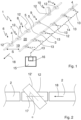
- FIG. 1 an embodiment of a calibration device 1 is shown schematically.
- the calibration device shown is used to calibrate a three-part road vehicle, namely a trackless tram with three cars, with two of the cars being movably connected to each other.
- Each of the three cars has two steered axles.
- the vehicle to be calibrated has two articulation angle sensors and twelve steering angle sensors.
- the articulation angle sensors are used to measure the articulation angle between two movably connected carriages compared to the zero position.
- the zero position is defined by the straight, aligned run of the carriages.
- the vehicle's steering angle sensors measure the steering angle of each wheel compared to the straight-line stability of the respective axle.
- the calibration device 1 consists of a first rail track 2 and a second rail track 3 as implementations of the first and second alignment aids in the sense of the present application, which are aligned parallel to one another and straight. If the trackless tram runs guided on the first and second rail tracks 2, 3, the three cars are aligned by definition and the zero position is fixed. If you now assign the current measured values of the vehicle's articulation angle sensors to the zero position, you have determined the essential value for calibrating the articulation angle sensors. The assignment of the zero position to the current measured value of the respective articulation angle sensor is stored in the vehicle control or in the joint control of the joints between the cars.
- each rail track 2, 3 has a tread 4 for the tire contact surfaces of the tires of the vehicle's wheels and a guide edge 5.
- the guide edges 5 each guide a wheel flange mounted on each wheel for calibration. Therefore, in the embodiment shown, the road vehicle behaves on the calibration device 1 like a rail vehicle.
- the calibration device 1 has six pairs 6 to 11 of first and second pivotable rail segments 12, 13 corresponding to the number of axles of the vehicle. These first and second pivotable rail segments 12, 13 form concrete embodiments of the pivotable segments within the meaning of the present application. These pivotable rail segments 12, 13 are used to calibrate a steering angle sensor on each wheel. In the illustrated embodiment, the pivotable first and second rail segments 12, 13 are in the in Figure 1 can be locked in the straight-ahead position shown, so that after the vehicle has driven onto the calibration device 1, all wheels are defined in the straight-ahead position.
- the straight-ahead position is then assigned to each current measured value from the twelve steering angle sensors and stored in the vehicle control system.
- the pivotable rail segments 12, 13 are mounted in a floating, pivotable manner, so that the fact is taken into account that the pivot axis of the wheels does not necessarily pass through the contact surfaces of the wheels.
- all wheels are initially steered in a first direction of rotation until the respective steering stop is reached.
- the direction of the pivoting movements of the individual wheels can be different or the same. If you imagine the cornering of a trackless tram with three cars and two steered axles per car, for example, when cornering on each car, the wheels of the first axle are steered in one direction and the wheels of the second axle are steered in the other direction . After reaching the maximum steering angle of each wheel in a first direction, the current measurement signal from the steering angle sensor of the respective wheel is assigned to the actually measured pivot angle ⁇ of the pivotable rail segment 12, 13 relative to the straight-ahead position.
- each pivotable rail segment 12, 13 has an electronic angle measuring device, which records the pivot angle with direction and amount compared to the straight-ahead position of the respective rail segment and sends it to a central control 15 via a bus line 14 the Calibration device 1 outputs. So that the values measured by the angle measuring devices for the deflection of the pivotable rail segments 12, 13 relative to the straight-ahead position in the vehicle control can be assigned to the respective measured values of the steering angle sensors, the control 15 of the calibration device 1 has an interface 16.
- the interface 16 is equipped with an interface complementary interface of the respective vehicle.
- Figure 2 shows a schematic top view of the first rail track 2 with a pivotable first rail segment 12. Shown is the straight-ahead position 17 and the position of the first rail segment 12 'when an exemplary steering stop of a steering movement of a wheel is reached.
- the swivel angle to be measured is designated ⁇ in the figure.
Landscapes
- Physics & Mathematics (AREA)
- General Physics & Mathematics (AREA)
- Length Measuring Devices With Unspecified Measuring Means (AREA)
- Steering Control In Accordance With Driving Conditions (AREA)
Claims (16)
- Dispositif d'étalonnage (1) permettant d'étalonner au moins un capteur d'angle d'articulation ou un capteur d'angle de direction d'un véhicule routier en plusieurs partiescomportant un premier moyen auxiliaire d'alignement (2),dans lequel le premier moyen auxiliaire d'alignement (2) s'étend en ligne droite dans une direction longitudinale (18), etdans lequel le premier moyen auxiliaire d'alignement (2) est conçu de telle sorte que les roues d'au moins un essieu d'un premier wagon du véhicule routier en plusieurs parties et les roues d'un essieu d'un second wagon du véhicule routier en plusieurs parties peuvent lui passer dessus, de telle sorte que le premier et le second wagon sont ainsi alignés dans une position en ligne droite,comportant au moins un premier segment (12, 12`) pouvant pivoter,dans lequel le premier segment (12, 12') pouvant pivoter est disposé à une première position (19) dans la direction longitudinale du premier moyen auxiliaire d'alignement (2) et dans lequel le premier segment (12, 12') peut être pivoté d'une position en ligne droite (17) à une position braquée, de sorte qu'une roue pouvant être dirigée d'un essieu du véhicule routier en plusieurs parties peut être pivotée avec le premier segment (12, 12').
- Dispositif d'étalonnage (1) selon la revendication précédente, dans lequel le dispositif d'étalonnage (1) présente un second moyen auxiliaire d'alignement (3), dans lequel le premier moyen auxiliaire d'alignement (2) et le second moyen auxiliaire d'alignement (3) s'étendent en ligne droite et parallèlement l'un à l'autre dans la direction longitudinale (18), et dans lequel le premier moyen auxiliaire d'alignement (2) et le second moyen auxiliaire d'alignement (3) sont disposés à une distance de voie (S) l'un par rapport à l'autre.
- Dispositif d'étalonnage (1) selon l'une des revendications précédentes, dans lequel au moins le premier ou le second moyen auxiliaire d'alignement (2, 3) est choisi parmi une ligne peinte ou projetée sur une surface praticable, une nervure faisant saillie par rapport à une surface, une cavité creusée dans une surface et une file de rails ou une combinaison de celles-ci.
- Dispositif d'étalonnage (1) selon l'une des revendications précédentes, dans lequel le dispositif d'étalonnage (1) présente une paire (6, 7, 8, 9, 10, 11) constituée du premier segment (12, 12') pouvant pivoter et d'un second segment (13) pouvant pivoter,dans lequel le second segment (13) pouvant pivoter est disposé à la première position (19) dans la direction longitudinale (18), etdans lequel le second segment (13) pouvant pivoter peut être pivoté d'une position en ligne droite (17) à une position braquée, de sorte que les roues pouvant être dirigées de l'essieu du véhicule routier peuvent être pivotées avec les premier et second segments (12, 12', 13).
- Dispositif d'étalonnage (1) selon l'une des revendications précédentes, dans lequel le dispositif d'étalonnage (1) présente un appareil de mesure d'angle permettant de détecter un angle de pivotement (α) d'au moins le premier ou le second segment (12, 12', 13) pouvant pivoter par rapport à la position en ligne droite (17).
- Dispositif d'étalonnage (1) selon l'une des revendications précédentes, dans lequel le dispositif d'étalonnage (1) présente au moins un premier segment (12, 12`) pouvant pivoter supplémentaire, de préférence une paire (6, 7, 8, 9, 10, 11) supplémentaire de premier et second segments (12, 12', 13) pouvant pivoter, à une seconde position (20) dans la direction longitudinale (18).
- Dispositif d'étalonnage (1) selon l'une des revendications précédentes lorsqu'elle dépend de la revendication 5, dans lequel le dispositif d'étalonnage (1) présente une commande (15), dans lequel la commande (15) est connectée de manière efficace à l'appareil de mesure d'angle de sorte que, lors du fonctionnement du dispositif d'étalonnage (1), la commande (15) reçoit un signal de mesure en provenance de l'appareil de mesure d'angle, et dans lequel la commande (15) présente une interface (16) qui peut être connectée à une interface (16) du véhicule routier et dans lequel la commande (15) est configurée de telle sorte que, lors du fonctionnement du dispositif d'étalonnage (1), la commande (15) émet, par l'intermédiaire de l'interface (16), un signal d'étalonnage pour au moins le capteur d'angle d'articulation ou le capteur d'angle de direction du véhicule routier.
- Dispositif d'étalonnage (1) selon l'une des revendications précédentes, dans lequel au moins le premier ou le second moyen auxiliaire d'alignement est une file de rails (2, 3) et dans lequel au moins la première ou la seconde file de rails (2, 3) est un profilé en forme de L ou un profilé en forme de U comportant une surface de roulement (4) pour une surface d'appui de pneumatique d'un pneumatique d'une roue du véhicule routier et au moins une surface de guidage permettant de guider une paroi latérale du pneumatique.
- Dispositif d'étalonnage (1) selon l'une des revendications précédentes, dans lequel au moins le premier ou le second segment (12, 12', 13) peut être bloqué dans la position en ligne droite (17).
- Dispositif d'étalonnage (1) selon l'une des revendications précédentes, dans lequel une distance dans la direction longitudinale (18) entre deux premiers segments (12, 12`) pouvant pivoter peut être modifiée de manière à pouvoir être réglée.
- Système comportant un dispositif d'étalonnage (1) selon l'une des revendications précédentes et un véhicule routier en plusieurs parties,
dans lequel le véhicule routier en plusieurs parties présente une pluralité de wagons reliés de manière mobile entre eux et une pluralité d'essieux comportant des roues comportant des pneumatiques. - Système selon la revendication précédente, dans lequel le véhicule routier en plusieurs parties présente une pluralité d'essieux dirigés, dans lequel la pluralité d'essieux dirigés sont de préférence disposés sur au moins un premier et un second wagon.
- Utilisation d'un dispositif d'étalonnage (1) selon l'une des revendications 1 à 10 ou d'un système selon l'une des revendications 11 ou 12 pour l'étalonnage d'au moins un capteur d'angle d'articulation ou d'un capteur d'angle de direction d'un véhicule routier en plusieurs parties.
- Procédé permettant d'étalonner au moins un capteur d'angle d'articulation ou un capteur d'angle de direction d'un véhicule routier en plusieurs parties comportant une pluralité de wagons reliés de manière mobile entre eux, comportant les étapes consistant àfaire passer une pluralité de roues du véhicule routier réparties sur la pluralité de wagons sur un premier moyen auxiliaire d'alignement (2),dans lequel le premier moyen auxiliaire d'alignement (2) s'étend en ligne droite dans une direction longitudinale (18),de sorte qu'au moins une roue d'un essieu pouvant être dirigé est disposée à une première position (19) dans la direction longitudinale (18) sur un premier segment (12, 12') pouvant pivoter autour d'un axe de pivotement etde sorte que les wagons sont alignés le long de la direction longitudinale (18) dans une position en ligne droite,aligner le premier segment (12, 12') pouvant pivoter dans une position en ligne droite (17) parallèle à la direction longitudinale (18) etau moinsmarquer une valeur de mesure actuelle du capteur d'angle de direction de l'essieu pouvant être dirigé comme position en ligne droite dans une commande (15) du véhicule routier oumarquer une valeur de mesure actuelle du capteur d'angle d'articulation comme position zéro dans une commande (15) du véhicule routier.
- Procédé selon la revendication 14, dans lequel le procédé présente en outre les étapes consistant àfaire pivoter la roue avec le premier segment (12, 12`) dans une première direction de direction vers une position braquée de l'essieu pouvant être dirigé,mesurer l'angle de pivotement réel du premier segment (12, 12`) par rapport à la position en ligne droite (17) etattribuer l'angle de pivotement réel à un signal de mesure actuel du capteur d'angle de direction de l'essieu pouvant être dirigé dans la commande (15) du véhicule.
- Procédé selon l'une des revendications 14 ou 15, dans lequel le procédé présente en outre les étapes consistant àbloquer le premier segment (12, 12`) dans la position en ligne droite (17) avant le passage du véhicule sur le premier moyen auxiliaire d'alignement,libérer le blocage du premier segment (12, 12`) avant le pivotement des roues etbloquer de nouveau le premier segment (12, 12`) lorsque l'étalonnage est terminé et que le premier segment (12, 12') est de nouveau dans la position en ligne droite (17).
Priority Applications (4)
| Application Number | Priority Date | Filing Date | Title |
|---|---|---|---|
| EP22150511.8A EP4209403B1 (fr) | 2022-01-07 | 2022-01-07 | Dispositif d'étalonnage permettant d'étalonner au moins un capteur d'angle de pivotement ou un capteur d'angle de braquage |
| HUE22150511A HUE066599T2 (hu) | 2022-01-07 | 2022-01-07 | Kalibráló eszköz legalább egy szög- vagy kormányszög-érzékelõ kalibrálására |
| PL22150511.8T PL4209403T3 (pl) | 2022-01-07 | 2022-01-07 | Urządzenie kalibracyjne do kalibracji co najmniej jednego czujnika kąta zginania lub czujnika kąta skrętu |
| ES22150511T ES2982764T3 (es) | 2022-01-07 | 2022-01-07 | Dispositivo de calibración para calibrar al menos un sensor de ángulo de flexión o un sensor de ángulo de dirección |
Applications Claiming Priority (1)
| Application Number | Priority Date | Filing Date | Title |
|---|---|---|---|
| EP22150511.8A EP4209403B1 (fr) | 2022-01-07 | 2022-01-07 | Dispositif d'étalonnage permettant d'étalonner au moins un capteur d'angle de pivotement ou un capteur d'angle de braquage |
Publications (3)
| Publication Number | Publication Date |
|---|---|
| EP4209403A1 EP4209403A1 (fr) | 2023-07-12 |
| EP4209403B1 true EP4209403B1 (fr) | 2024-03-06 |
| EP4209403C0 EP4209403C0 (fr) | 2024-03-06 |
Family
ID=79282892
Family Applications (1)
| Application Number | Title | Priority Date | Filing Date |
|---|---|---|---|
| EP22150511.8A Active EP4209403B1 (fr) | 2022-01-07 | 2022-01-07 | Dispositif d'étalonnage permettant d'étalonner au moins un capteur d'angle de pivotement ou un capteur d'angle de braquage |
Country Status (4)
| Country | Link |
|---|---|
| EP (1) | EP4209403B1 (fr) |
| ES (1) | ES2982764T3 (fr) |
| HU (1) | HUE066599T2 (fr) |
| PL (1) | PL4209403T3 (fr) |
Family Cites Families (5)
| Publication number | Priority date | Publication date | Assignee | Title |
|---|---|---|---|---|
| DE102014102302A1 (de) * | 2014-02-21 | 2015-08-27 | Claas Saulgau Gmbh | Verfahren zur Kalibrierung eines gezogenen oder selbstfahrenden Nutzfahrzeugs mit mindestens einer lenkbaren Achse |
| DE102017203426A1 (de) * | 2017-03-02 | 2018-09-06 | Robert Bosch Gmbh | Kalibrierboden, Messvorrichtung und Verfahren zur Kalibrierung von Fahrerassistenzsystemen |
| DE102017209980A1 (de) * | 2017-06-13 | 2018-12-13 | Bayerische Motoren Werke Aktiengesellschaft | Steuersystem zum Lenken eines Zugfahrzeuges mit einem Anhänger |
| DE102019109191A1 (de) * | 2018-04-18 | 2019-10-24 | Lemken Gmbh & Co. Kg | Verfahren zur Kurvenradiusermittlung |
| DE102018117353A1 (de) * | 2018-07-18 | 2020-01-23 | Man Truck & Bus Se | Verfahren zur Knickwinkelbestimmung bei einem Fahrzeuggespann |
-
2022
- 2022-01-07 HU HUE22150511A patent/HUE066599T2/hu unknown
- 2022-01-07 EP EP22150511.8A patent/EP4209403B1/fr active Active
- 2022-01-07 ES ES22150511T patent/ES2982764T3/es active Active
- 2022-01-07 PL PL22150511.8T patent/PL4209403T3/pl unknown
Also Published As
| Publication number | Publication date |
|---|---|
| PL4209403T3 (pl) | 2024-06-10 |
| HUE066599T2 (hu) | 2024-08-28 |
| EP4209403A1 (fr) | 2023-07-12 |
| ES2982764T3 (es) | 2024-10-17 |
| EP4209403C0 (fr) | 2024-03-06 |
Similar Documents
| Publication | Publication Date | Title |
|---|---|---|
| EP2634071B1 (fr) | Procédé et dispositif de commande du procédé de maneuvre d'un train de véhicule automobile | |
| DE102012006206B4 (de) | Verfahren und Vorrichtung zur Erfassung einer drohenden Kollision zwischen einem Zugfahrzeug und seinem Anhänger | |
| EP2069714B1 (fr) | Procede pour la mesure du train de roulement d`un vehicule automobile, dispositif de mesure du train de roulement ainsi que voie de controle | |
| DE10154612A1 (de) | Vorrichtung zum Lenken eines Zugfahrzeuges mit einem Anhänger bei Rückwärtsfahrt | |
| DE69510871T2 (de) | Steuerverfahren zur Lenkung von Laufwerken mit einstellbaren Rädern einer auf Schienen fahrenden Einheit und dieses Verfahren nutzende Einheit | |
| DE19806655A1 (de) | Elektronische Rangierhilfe für einen Lastwagen mit Anhänger | |
| EP3090922A1 (fr) | Procede de direction d'une remorque agricole et ensemble de traction | |
| DE4133882A1 (de) | Verfahren zum selbsttaetigen nachfuehren eines fahrzeugs auf der spur eines vorausfahrenden fahrzeugs | |
| DE102012207647B4 (de) | Fahrerassistenzsystem zum Rückwärtsfahren eines zweispurigen Kraftfahrzeugs mit einem Anhänger | |
| DE102018210340B4 (de) | Verfahren und System zum Ermitteln einer Relativpose zwischen einem Zielobjekt und einem Fahrzeug | |
| DE102008045377A1 (de) | Verfahren und Vorrichtung zur Unterstützung eines Einparkvorgangs eines Fahrzeugs | |
| DE3514759A1 (de) | Einrichtung zur vermessung der achsgeometrie an den radachsen von kraftfahrzeugen bei drehenden raedern | |
| EP1270814A2 (fr) | Procédé et machine pour mesurer une voie ferrée | |
| EP0292855A1 (fr) | Procédé et dispositif pour contrôler et ajuster les mécanismes de roulement des véhicules | |
| DE102014214141B4 (de) | Verfahren sowie Steuergerät zum Bestimmen eines Winkels zwischen Längsachsen eines Gespanns aus Fahrzeugsegmenten | |
| DE102015210816B4 (de) | Verfahren für einen Anhängerrangierassistenten | |
| EP3608205B1 (fr) | Procédé de détermination de l'angle de flèche d'un attelage de véhicule | |
| DE19834752A1 (de) | Vorrichtung zur Regelung der Rückwärtsfahrt von Kraftfahrzeugen mit Anhängern | |
| DE102007048069A1 (de) | Vorrichtung und Verfahren zum Rangieren von Anhängern | |
| EP2950040A1 (fr) | Procédé et système d'assistance du conducteur pour l'assistance d'un ensemble attelé de véhicule utilitaire | |
| EP2910099B1 (fr) | Procédé d'étalonnage d'un véhicule utilitaire tracté ou auto-tracté comprenant au moins un essieu orientable | |
| EP4209403A1 (fr) | Dispositif d'étalonnage permettant d'étalonner au moins un capteur d'angle de pivotement ou un capteur d'angle de braquage | |
| DE19636427C3 (de) | Verfahren und Vorrichtung zum Messen und Einstellen der Achsgeometrie eines Fahrzeugs | |
| WO1999065751A1 (fr) | Procede de reconnaissance de courbes et d'alignement d'essieux pour vehicules sur rails | |
| EP3455689B1 (fr) | Procédé et système pour guider des convois ferroviaires et des rames de véhicules qui sont accouplés mécaniquement ou se suivent librement sans rails mécaniques |
Legal Events
| Date | Code | Title | Description |
|---|---|---|---|
| PUAI | Public reference made under article 153(3) epc to a published international application that has entered the european phase |
Free format text: ORIGINAL CODE: 0009012 |
|
| STAA | Information on the status of an ep patent application or granted ep patent |
Free format text: STATUS: REQUEST FOR EXAMINATION WAS MADE |
|
| 17P | Request for examination filed |
Effective date: 20220926 |
|
| AK | Designated contracting states |
Kind code of ref document: A1 Designated state(s): AL AT BE BG CH CY CZ DE DK EE ES FI FR GB GR HR HU IE IS IT LI LT LU LV MC MK MT NL NO PL PT RO RS SE SI SK SM TR |
|
| GRAP | Despatch of communication of intention to grant a patent |
Free format text: ORIGINAL CODE: EPIDOSNIGR1 |
|
| STAA | Information on the status of an ep patent application or granted ep patent |
Free format text: STATUS: GRANT OF PATENT IS INTENDED |
|
| INTG | Intention to grant announced |
Effective date: 20230829 |
|
| GRAS | Grant fee paid |
Free format text: ORIGINAL CODE: EPIDOSNIGR3 |
|
| GRAA | (expected) grant |
Free format text: ORIGINAL CODE: 0009210 |
|
| STAA | Information on the status of an ep patent application or granted ep patent |
Free format text: STATUS: THE PATENT HAS BEEN GRANTED |
|
| AK | Designated contracting states |
Kind code of ref document: B1 Designated state(s): AL AT BE BG CH CY CZ DE DK EE ES FI FR GB GR HR HU IE IS IT LI LT LU LV MC MK MT NL NO PL PT RO RS SE SI SK SM TR |
|
| REG | Reference to a national code |
Ref country code: CH Ref legal event code: EP |
|
| REG | Reference to a national code |
Ref country code: DE Ref legal event code: R096 Ref document number: 502022000575 Country of ref document: DE |
|
| REG | Reference to a national code |
Ref country code: IE Ref legal event code: FG4D Free format text: LANGUAGE OF EP DOCUMENT: GERMAN |
|
| U01 | Request for unitary effect filed |
Effective date: 20240328 |
|
| U07 | Unitary effect registered |
Designated state(s): AT BE BG DE DK EE FI FR IT LT LU LV MT NL PT SE SI Effective date: 20240410 |
|
| PG25 | Lapsed in a contracting state [announced via postgrant information from national office to epo] |
Ref country code: GR Free format text: LAPSE BECAUSE OF FAILURE TO SUBMIT A TRANSLATION OF THE DESCRIPTION OR TO PAY THE FEE WITHIN THE PRESCRIBED TIME-LIMIT Effective date: 20240607 |
|
| PG25 | Lapsed in a contracting state [announced via postgrant information from national office to epo] |
Ref country code: HR Free format text: LAPSE BECAUSE OF FAILURE TO SUBMIT A TRANSLATION OF THE DESCRIPTION OR TO PAY THE FEE WITHIN THE PRESCRIBED TIME-LIMIT Effective date: 20240306 Ref country code: RS Free format text: LAPSE BECAUSE OF FAILURE TO SUBMIT A TRANSLATION OF THE DESCRIPTION OR TO PAY THE FEE WITHIN THE PRESCRIBED TIME-LIMIT Effective date: 20240606 |
|
| PG25 | Lapsed in a contracting state [announced via postgrant information from national office to epo] |
Ref country code: RS Free format text: LAPSE BECAUSE OF FAILURE TO SUBMIT A TRANSLATION OF THE DESCRIPTION OR TO PAY THE FEE WITHIN THE PRESCRIBED TIME-LIMIT Effective date: 20240606 Ref country code: NO Free format text: LAPSE BECAUSE OF FAILURE TO SUBMIT A TRANSLATION OF THE DESCRIPTION OR TO PAY THE FEE WITHIN THE PRESCRIBED TIME-LIMIT Effective date: 20240606 Ref country code: HR Free format text: LAPSE BECAUSE OF FAILURE TO SUBMIT A TRANSLATION OF THE DESCRIPTION OR TO PAY THE FEE WITHIN THE PRESCRIBED TIME-LIMIT Effective date: 20240306 Ref country code: GR Free format text: LAPSE BECAUSE OF FAILURE TO SUBMIT A TRANSLATION OF THE DESCRIPTION OR TO PAY THE FEE WITHIN THE PRESCRIBED TIME-LIMIT Effective date: 20240607 |
|
| REG | Reference to a national code |
Ref country code: HU Ref legal event code: AG4A Ref document number: E066599 Country of ref document: HU |
|
| PG25 | Lapsed in a contracting state [announced via postgrant information from national office to epo] |
Ref country code: IS Free format text: LAPSE BECAUSE OF FAILURE TO SUBMIT A TRANSLATION OF THE DESCRIPTION OR TO PAY THE FEE WITHIN THE PRESCRIBED TIME-LIMIT Effective date: 20240706 |
|
| PG25 | Lapsed in a contracting state [announced via postgrant information from national office to epo] |
Ref country code: SM Free format text: LAPSE BECAUSE OF FAILURE TO SUBMIT A TRANSLATION OF THE DESCRIPTION OR TO PAY THE FEE WITHIN THE PRESCRIBED TIME-LIMIT Effective date: 20240306 |
|
| REG | Reference to a national code |
Ref country code: ES Ref legal event code: FG2A Ref document number: 2982764 Country of ref document: ES Kind code of ref document: T3 Effective date: 20241017 |
|
| PG25 | Lapsed in a contracting state [announced via postgrant information from national office to epo] |
Ref country code: CZ Free format text: LAPSE BECAUSE OF FAILURE TO SUBMIT A TRANSLATION OF THE DESCRIPTION OR TO PAY THE FEE WITHIN THE PRESCRIBED TIME-LIMIT Effective date: 20240306 |
|
| PG25 | Lapsed in a contracting state [announced via postgrant information from national office to epo] |
Ref country code: SK Free format text: LAPSE BECAUSE OF FAILURE TO SUBMIT A TRANSLATION OF THE DESCRIPTION OR TO PAY THE FEE WITHIN THE PRESCRIBED TIME-LIMIT Effective date: 20240306 |
|
| PG25 | Lapsed in a contracting state [announced via postgrant information from national office to epo] |
Ref country code: SM Free format text: LAPSE BECAUSE OF FAILURE TO SUBMIT A TRANSLATION OF THE DESCRIPTION OR TO PAY THE FEE WITHIN THE PRESCRIBED TIME-LIMIT Effective date: 20240306 Ref country code: SK Free format text: LAPSE BECAUSE OF FAILURE TO SUBMIT A TRANSLATION OF THE DESCRIPTION OR TO PAY THE FEE WITHIN THE PRESCRIBED TIME-LIMIT Effective date: 20240306 Ref country code: RO Free format text: LAPSE BECAUSE OF FAILURE TO SUBMIT A TRANSLATION OF THE DESCRIPTION OR TO PAY THE FEE WITHIN THE PRESCRIBED TIME-LIMIT Effective date: 20240306 Ref country code: IS Free format text: LAPSE BECAUSE OF FAILURE TO SUBMIT A TRANSLATION OF THE DESCRIPTION OR TO PAY THE FEE WITHIN THE PRESCRIBED TIME-LIMIT Effective date: 20240706 Ref country code: CZ Free format text: LAPSE BECAUSE OF FAILURE TO SUBMIT A TRANSLATION OF THE DESCRIPTION OR TO PAY THE FEE WITHIN THE PRESCRIBED TIME-LIMIT Effective date: 20240306 |
|
| REG | Reference to a national code |
Ref country code: DE Ref legal event code: R097 Ref document number: 502022000575 Country of ref document: DE |
|
| PLBE | No opposition filed within time limit |
Free format text: ORIGINAL CODE: 0009261 |
|
| STAA | Information on the status of an ep patent application or granted ep patent |
Free format text: STATUS: NO OPPOSITION FILED WITHIN TIME LIMIT |
|
| 26N | No opposition filed |
Effective date: 20241209 |
|
| U20 | Renewal fee for the european patent with unitary effect paid |
Year of fee payment: 4 Effective date: 20250127 |
|
| REG | Reference to a national code |
Ref country code: CH Ref legal event code: PL |
|
| PG25 | Lapsed in a contracting state [announced via postgrant information from national office to epo] |
Ref country code: MC Free format text: LAPSE BECAUSE OF FAILURE TO SUBMIT A TRANSLATION OF THE DESCRIPTION OR TO PAY THE FEE WITHIN THE PRESCRIBED TIME-LIMIT Effective date: 20240306 |
|
| PG25 | Lapsed in a contracting state [announced via postgrant information from national office to epo] |
Ref country code: CH Free format text: LAPSE BECAUSE OF NON-PAYMENT OF DUE FEES Effective date: 20250131 |
|
| PG25 | Lapsed in a contracting state [announced via postgrant information from national office to epo] |
Ref country code: IE Free format text: LAPSE BECAUSE OF NON-PAYMENT OF DUE FEES Effective date: 20250107 |
|
| PGFP | Annual fee paid to national office [announced via postgrant information from national office to epo] |
Ref country code: PL Payment date: 20251230 Year of fee payment: 5 |
|
| PGFP | Annual fee paid to national office [announced via postgrant information from national office to epo] |
Ref country code: HU Payment date: 20260108 Year of fee payment: 5 |
|
| U20 | Renewal fee for the european patent with unitary effect paid |
Year of fee payment: 5 Effective date: 20260128 |
|
| PGFP | Annual fee paid to national office [announced via postgrant information from national office to epo] |
Ref country code: ES Payment date: 20260217 Year of fee payment: 5 |
|
| PGFP | Annual fee paid to national office [announced via postgrant information from national office to epo] |
Ref country code: TR Payment date: 20260106 Year of fee payment: 5 |