EP4209436A1 - Appareil de transport de particules de polymères - Google Patents
Appareil de transport de particules de polymères Download PDFInfo
- Publication number
- EP4209436A1 EP4209436A1 EP22150679.3A EP22150679A EP4209436A1 EP 4209436 A1 EP4209436 A1 EP 4209436A1 EP 22150679 A EP22150679 A EP 22150679A EP 4209436 A1 EP4209436 A1 EP 4209436A1
- Authority
- EP
- European Patent Office
- Prior art keywords
- chamber
- fluid stream
- conveying fluid
- particle conveying
- polymer particles
- Prior art date
- Legal status (The legal status is an assumption and is not a legal conclusion. Google has not performed a legal analysis and makes no representation as to the accuracy of the status listed.)
- Granted
Links
Images


Classifications
-
- B—PERFORMING OPERATIONS; TRANSPORTING
- B01—PHYSICAL OR CHEMICAL PROCESSES OR APPARATUS IN GENERAL
- B01J—CHEMICAL OR PHYSICAL PROCESSES, e.g. CATALYSIS OR COLLOID CHEMISTRY; THEIR RELEVANT APPARATUS
- B01J8/00—Chemical or physical processes in general, conducted in the presence of fluids and solid particles; Apparatus for such processes
- B01J8/0015—Feeding of the particles in the reactor; Evacuation of the particles out of the reactor
-
- B—PERFORMING OPERATIONS; TRANSPORTING
- B65—CONVEYING; PACKING; STORING; HANDLING THIN OR FILAMENTARY MATERIAL
- B65G—TRANSPORT OR STORAGE DEVICES, e.g. CONVEYORS FOR LOADING OR TIPPING, SHOP CONVEYOR SYSTEMS OR PNEUMATIC TUBE CONVEYORS
- B65G53/00—Conveying materials in bulk through troughs, pipes or tubes by floating the materials or by flow of gas, liquid or foam
- B65G53/34—Details
- B65G53/60—Devices for separating the materials from propellant gas
-
- B—PERFORMING OPERATIONS; TRANSPORTING
- B65—CONVEYING; PACKING; STORING; HANDLING THIN OR FILAMENTARY MATERIAL
- B65G—TRANSPORT OR STORAGE DEVICES, e.g. CONVEYORS FOR LOADING OR TIPPING, SHOP CONVEYOR SYSTEMS OR PNEUMATIC TUBE CONVEYORS
- B65G53/00—Conveying materials in bulk through troughs, pipes or tubes by floating the materials or by flow of gas, liquid or foam
- B65G53/04—Conveying materials in bulk pneumatically through pipes or tubes; Air slides
- B65G53/06—Gas pressure systems operating without fluidisation of the materials
- B65G53/10—Gas pressure systems operating without fluidisation of the materials with pneumatic injection of the materials by the propelling gas
- B65G53/12—Gas pressure systems operating without fluidisation of the materials with pneumatic injection of the materials by the propelling gas the gas flow acting directly on the materials in a reservoir
-
- B—PERFORMING OPERATIONS; TRANSPORTING
- B65—CONVEYING; PACKING; STORING; HANDLING THIN OR FILAMENTARY MATERIAL
- B65G—TRANSPORT OR STORAGE DEVICES, e.g. CONVEYORS FOR LOADING OR TIPPING, SHOP CONVEYOR SYSTEMS OR PNEUMATIC TUBE CONVEYORS
- B65G53/00—Conveying materials in bulk through troughs, pipes or tubes by floating the materials or by flow of gas, liquid or foam
- B65G53/34—Details
- B65G53/66—Use of indicator or control devices, e.g. for controlling gas pressure, for controlling proportions of material and gas, for indicating or preventing jamming of material
-
- B—PERFORMING OPERATIONS; TRANSPORTING
- B01—PHYSICAL OR CHEMICAL PROCESSES OR APPARATUS IN GENERAL
- B01J—CHEMICAL OR PHYSICAL PROCESSES, e.g. CATALYSIS OR COLLOID CHEMISTRY; THEIR RELEVANT APPARATUS
- B01J2208/00—Processes carried out in the presence of solid particles; Reactors therefor
- B01J2208/00743—Feeding or discharging of solids
- B01J2208/00769—Details of feeding or discharging
-
- B—PERFORMING OPERATIONS; TRANSPORTING
- B65—CONVEYING; PACKING; STORING; HANDLING THIN OR FILAMENTARY MATERIAL
- B65G—TRANSPORT OR STORAGE DEVICES, e.g. CONVEYORS FOR LOADING OR TIPPING, SHOP CONVEYOR SYSTEMS OR PNEUMATIC TUBE CONVEYORS
- B65G2201/00—Indexing codes relating to handling devices, e.g. conveyors, characterised by the type of product or load being conveyed or handled
- B65G2201/04—Bulk
-
- B—PERFORMING OPERATIONS; TRANSPORTING
- B65—CONVEYING; PACKING; STORING; HANDLING THIN OR FILAMENTARY MATERIAL
- B65G—TRANSPORT OR STORAGE DEVICES, e.g. CONVEYORS FOR LOADING OR TIPPING, SHOP CONVEYOR SYSTEMS OR PNEUMATIC TUBE CONVEYORS
- B65G2207/00—Indexing codes relating to constructional details, configuration and additional features of a handling device, e.g. Conveyors
- B65G2207/32—Noise prevention features
Definitions
- the invention refers to an apparatus for conveying polymer particles, particularly cellular or foamed polymer particles, from a first location to a second location.
- Respective apparatuses for conveying polymer particles are generally known from the field of polymer processing and generally enable conveying polymer particles from a first location to a second location.
- An exemplary first location can be a first polymer processing site, such as e.g. a polymer particle production site
- an exemplary second location can be a second polymer processing site, such as e.g. a polymer particle testing site, a polymer particle packaging site, or a polymer part manufacturing site.
- conveying polymer particles comprises conveying the polymer particles in a pressurized fluid stream, such as a pressurized gas stream.
- a pressurized fluid stream such as a pressurized gas stream.
- the particles are typically conveyed in a pressurized fluid stream and thus, after being conveyed from a respective first location to a respective second location, need to be decompressed or depressurized at the second location.
- depressurizing is a challenge and the principles known from prior art are oftentimes technically immature with respect to the decompression or depressurization of the polymer particles such that there exists a need for an improved principle of decompression or depressurization of respective polymer particles.
- an objective of the present invention to provide an apparatus for conveying polymer particles from a first location to a second location which enables an improved decompression or depressurization of polymer particles contained within a pressurized fluid.
- a first aspect of the invention relates to an apparatus for conveying polymer particles, particularly cellular or foamed polymer particles, i.e. polymer particles having a cellular or foamed structure, from a first location to a second location.
- the apparatus is thus, configured to convey respective polymer particles from a first location to a second location.
- An exemplary first location can be a first polymer processing site, such as e.g. a polymer particle production site
- an exemplary second location can be a second polymer processing site, such as e.g. a polymer particle testing site, a polymer particle packaging site, a polymer part manufacturing site, etc.
- At least one of the first and second location can also be a particle storage device, e.g. a tank, for storing polymer particles.
- the apparatus comprises a pressurizing unit and a decompression or depressurizing unit whose function and structure will be specified in the following:
- the pressurizing unit is configured to generate a pressurized particle conveying fluid stream.
- the pressurized particle conveying fluid stream typically, comprises polymer particles in a pressurized fluid.
- the pressurized fluid can be a gas.
- the gas can e.g. be air or an inert gas, such as Argon, Helium, CO 2 , etc.
- the pressurized particle conveying fluid stream has a first pressure level.
- the first pressure level can range between 1 bar and 1000 bar, for instance.
- the first pressure level can thus, be 1 bar, 2 bar, 3 bar, 4 bar, 5 bar, 6 bar, 7 bar, 8 bar, 9 bar, 10 bar, 11 bar, 12 bar, 13 bar, 14 bar, 15 bar, 16 bar, 17 bar, 18 bar, 19 bar, 20 bar, 21 bar, 22 bar, 23 bar, 24 bar, 25 bar, 26 bar, 27 bar, 28 bar, 29 bar, 30 bar, 31 bar, 32 bar, 33 bar, 34 bar, 35 bar, 36 bar, 37 bar, 38 bar, 39 bar, 40 bar, 41 bar, 42 bar, 43 bar, 44 bar, 45 bar, 46 bar, 47 bar, 48 bar, 49 bar, 50 bar, 51 bar, 52 bar, 53 bar, 54 bar, 55 bar, 56 bar, 57 bar, 58 bar, 59 bar, 60 bar, 61 bar, 62 bar, 63 bar, 64 bar, 65 bar, 66 bar, 67 bar, 68 bar, 69 bar, 70 bar, 71 bar, 72 bar, 73 bar, 74 bar, 75 bar, 76 bar, 77 bar,
- Each of the aforementioned exemplary values can also be deemed a lower or upper threshold value of a pressure range of the pressurized particle conveying fluid stream.
- the aforementioned exemplary pressure levels/values typically, refer to absolute pressure levels/values.
- the aforementioned pressure levels/values can also be used as threshold values of pressure level intervals.
- the decompressing unit is configured to decompress the pressurized particle conveying fluid stream from the first pressure level to a second pressure level lower than the first pressure level.
- the decompressing unit is thus, configured to generate a decompressed particle conveying fluid stream having a second pressure level lower than the first pressure level.
- decompression comprises reducing the pressure level of the pressurized particle conveying fluid stream from the first pressure level to the second pressure level.
- the second pressure level can be atmospheric pressure, lower than atmospheric pressure, or higher than atmospheric pressure with the premise that it is below the first pressure level.
- the particles can be conveyed by gravity forces and/or conveying fluids after decompressing the pressurized particle conveying fluid stream.
- the pressurizing unit and the decompressing unit are typically, connected via suitable connecting means, such as tubes, hoses, pipes etc., which enable that the pressurized particle conveying fluid stream can stream from the pressurizing unit, i.e. particularly an outlet opening of the pressurizing unit, to the decompressing unit, i.e. particularly an inlet opening of the decompressing unit.
- the apparatus can comprise a connecting unit comprising at least one connecting element, such as a tube, hose, pipe, etc., connecting the pressurizing unit with the decompressing unit.
- the decompressing unit is typically, arranged downstream of the pressurizing unit.
- the decompressing unit comprises a first chamber and a second chamber.
- the first chamber is configured to receive the pressurized particle conveying fluid stream.
- the first chamber can comprise an inlet opening of the decompressing unit or can at least directly or indirectly communicate with an inlet opening of the decompressing unit.
- the first chamber can have a hollow-cylindrical basic shape which defines a central axis of the first chamber.
- the first chamber can be built from at least one duct- or pipe-element.
- the first chamber can thus, comprise a duct- or pipe-like shape.
- the first chamber is thus, scalable by choosing appropriate duct- or pipe-elements.
- the first chamber comprises or is delimited by a first wall structure which defines or delimits a first volume which represents the (inner) volume of the first chamber.
- the first chamber can thus, be generally configured as a tube or a pipe, for instance.
- the second chamber surrounds the first chamber.
- the second chamber can also have a hollow-cylindrical basic shape which defines a central axis of the second chamber.
- the second chamber can be built from at least one duct- or pipe-element.
- the second chamber can thus, comprise a duct- or pipe-like shape.
- the second chamber is thus, scalable by choosing appropriate duct- or pipe-elements.
- the second chamber comprises or is delimited by a second wall structure which defines or delimits a second volume which represents the (inner) volume of the second chamber.
- the first chamber and the second chamber can thus, be coaxially arranged.
- the inner diameter, of the second chamber are typically larger than the dimensions, i.e. particularly the outer diameter, of the first chamber such that the second chamber can thus, surround the first chamber.
- the first chamber can thus, be accommodated in the (inner) volume of the second chamber.
- the first and second chambers can be arranged with an angle, e.g. with an angle of 90°, relative to a horizontal reference plane, e.g. defined by a ground.
- the first and second chambers can be vertically arranged with their respective central axes being oriented approx. 90° relative to a respective horizontal reference plane.
- the particles can be conveyed through the decompressing unit, i.e. particularly through the first camber, e.g. by gravity forces after decompressing the pressurized particle conveying fluid stream as explained above.
- the first chamber is delimited by a first wall structure and the second chamber is delimited by a second wall structure.
- the first wall structure comprises at least one first opening through which an inner volume of the first chamber (i.e. the first volume) is connected with an inner volume of the second chamber (i.e. the second volume) and the second wall structure comprises at least one second opening through which the inner volume of the second chamber (i.e. the second volume) can be connected with at least one dampening device (if present).
- the decompressing unit comprises a specific fluid communication arrangement of the first chamber and the second chamber.
- the first chamber and the second chamber are in fluid communication, which enables that a fluid inside the first chamber can, particularly radially, enter the second chamber from the first chamber through the at least one first opening provided with the first wall structure.
- the dimensions of the at least one first opening is typically, small enough to impede that polymer particles within the pressurized particle conveying fluid stream can enter the second chamber. Hence, the dimensions of the at least one first opening is typically, at least smaller than the minimum particle size or the mean average particle size of the polymer particles within the pressurized particle conveying fluid stream.
- the first wall structure thus, acts as a separation or screening, or sieving means configured to separate, screen, or sieve the polymer particles within the pressurized particle conveying fluid stream from the pressurized particle conveying fluid stream while the pressurized particle conveying fluid stream is decompressed at the same time.
- the configuration of the decompressing unit enables decompressing polymer particles without causing damage to the polymer particles. Particularly, no visually perceivable damage is caused to the polymer particles.
- the decompressing unit can further comprise at least one dampening device.
- the at least one dampening device is configured to dampen noise generated through decompressing of the pressurized particle conveying fluid stream via the decompressing unit.
- the at least one dampening device can comprise a housing having an inner space including a noise dampening structure, e.g. a baffle structure, for dampening noise generated through decompressing of the pressurized particle conveying fluid stream via the decompressing unit.
- the noise dampening structure can comprise a multi-dimensional arrangement of baffle elements which are positioned and/or oriented to dampen respective noise.
- the housing can comprise an inlet for a fluid stream entering the at least one dampening device and an outlet for a fluid stream exiting the dampening device.
- the noise dampening structure is arranged or formed between the inlet and the outlet.
- the at least one dampening device can thus, be formed as a sound suppressor device.
- the second chamber and the at least one dampening device i.e. particularly a respective inner space of the at least one dampening device which includes a dampening structure, can be in fluid communication, which enables that a fluid inside the second chamber, e.g. a fluid which has entered the second chamber through the at least one first opening, can, particularly radially, enter the inner space of the at least one dampening device from the second chamber through the at least one second opening provided with the second wall structure.
- the first chamber can comprise at least one inlet opening for the pressurized particle conveying fluid stream and at least one outlet opening for the decompressed particle conveying fluid stream.
- At least one inlet control device can be assigned to the at least one inlet opening of the first chamber.
- the at least one inlet control device is configured to control an amount of pressurized particle conveying fluid stream to enter the first chamber via the at least one inlet opening. Hence, exact control of the amount of pressurized particle conveying fluid stream to enter the first chamber via the at least one inlet opening can be determined by the at least one inlet control device.
- the at least one inlet control device can comprise at least one shutter element moveably supported between at least two orientations and/or positions, wherein at least one first orientation and/or position corresponds to an open state of the at least one inlet control device in which an amount of pressurized particle conveying fluid stream can enter the first chamber via the at least one inlet opening, and at least one second orientation and/or position corresponds to a closed state of the at least one inlet control device in which an amount of pressurized particle conveying fluid stream cannot enter the first chamber via the at least one inlet opening. Operation of the at least one inlet control device, i.e.
- the at least one inlet control device can be built as or comprise at least one valve device.
- a respective valve device typically, comprises at least one valve element (shutter element) moveably supported between at least one open state at least one closed state as specified in context with the at least one inlet control device.
- a respective valve device can be connected with at least one actuating device for actuating a respective valve element to transfer the at least one valve element between a respective open and closed state and vice versa.
- At least one outlet control device can be assigned to the at least one outlet opening of the first chamber.
- the at least one outlet control device is configured to control an amount of decompressed particle conveying fluid stream and/or the amount of decompressed polymer particles to exit the first chamber via the at least one outlet opening.
- exact control of the amount of the decompressed particle conveying fluid stream and/or the amount of decompressed polymer particles to exit the first chamber via the at least one outlet opening can be determined by the at least one outlet control device.
- the at least one outlet control device can comprise at least one shutter element moveably supported between at least two orientations and/or positions, wherein at least one first orientation and/or position corresponds to an open state of the at least one outlet control device in which an amount of decompressed particle conveying fluid stream can exit the first chamber via the at least one outlet opening, and at least one second orientation and/or position corresponds to a closed state of the at least one outlet control device in which an amount of decompressed particle conveying fluid stream cannot exit the first chamber via the at least one outlet opening. Operation of the at least one outlet control device, i.e.
- the at least one the outlet control device can be built as or comprise at least one valve device.
- a respective valve device typically, comprises at least one valve element (shutter element) moveably supported between at least one open state at least one closed state as specified in context with the at least one outlet control device.
- a respective valve device can be connected with at least one actuating device for actuating a respective valve element to transfer the at least one valve element between a respective open and closed state and vice versa.
- Operation of the at least one inlet control device and the at least one outlet control device is typically, synchronized via respective hardware- and/or software-embodied control devices of the at least one inlet control device and the at least one outlet control device or via a superordinate hardware- and/or software-embodied control device of the decompressing unit or the apparatus, respectively.
- the at least one outlet control device has been previously transferred in its closed state and vice versa.
- transferring the at least one inlet control device in the open state typically, takes place when the at least one outlet control device is in the closed state and vice versa.
- synchronizing typically means that the at least one inlet control device and the at least one outlet control are never in their respective open state and/or closed state at the same time.
- the first wall structure delimiting the first chamber can comprise not only one, but a plurality of first openings forming a mesh or screen structure.
- the openings can generally have bore- or slit-like shapes. Yet, as mentioned above, the dimensions of the openings typically, impede that polymer particles within the pressurized particle conveying fluid stream can enter the second chamber.
- one, a plurality of, or all first openings can have varying dimensions, particularly a varying cross-section, between an inlet portion through which a particle conveying fluid stream enters the at least one opening from the first chamber to an outlet portion through which a particle conveying fluid stream exits the at least one opening into the second chamber.
- the wall portions of the first wall structure delimiting the at least one first opening can be inclined relative to a central axis of the first chamber, particularly relative to an auxiliary axis radially extending off the central axis of the first chamber.
- the first wall structure delimiting the first chamber is built from or comprises a wire wrapped mesh or a wire wrapped screen.
- a respective wire wrapped mesh or a wire wrapped screen can have a hollow-cylindrical shape which also defines the hollow-cylindrical basic shape of the first chamber.
- Respective wire wrapped mesh or a wire wrapped screen enable a cost-effective and highly efficient separation of polymer particles from a respective pressurized particle conveying fluid stream.
- the decompressing unit can comprise a plurality of respective dampening devices located at different positions, e.g. at different axial and/or radial and/or circumferential positions, relative to the circumferential and/or longitudinal extension of the decompressing unit.
- the decompressing unit can comprise a plurality of dampening devices arranged at different positions relative to the circumferential and/or longitudinal extension of the decompressing unit, for instance. Arranging respective dampening devices at different axial and/or radial and/or circumferential positions enables a more homogenous decompression. By increasing the number of dampening devices, the dampening efficiency can be increased.
- at least two dampening devices can differ in their dampening properties, e.g. due to different dampening structure designs.
- At least two dampening devices disposed at the same axial position, yet at different circumferentially positions, e.g. at opposing circumferential positions, can form a dampening group or dampening stage, respectively.
- the decompressing unit can comprise a plurality of such dampening groups or dampening stages at different axial positions. Respective dampening stages can comprise the same number or a different number of dampening devices.
- the apparatus can comprise a cleaning fluid stream generating unit for generating a pressurized cleaning fluid stream for cleaning the decompressing unit from residue polymer particles.
- the cleaning stream particularly, serves for cleaning the first chamber from particle residues which have not been removed through a respective outlet opening of the first chamber.
- the cleaning stream can serve for cleaning respective connecting means connecting the pressurizing unit and the decompressing unit.
- the cleaning fluid stream generating unit can be identical with the pressurizing unit.
- the pressurizing unit can also be configured to generate a respective cleaning fluid stream which does not comprise polymer particles to be conveyed.
- the cleaning fluid stream can also be a gas stream, such as an air stream or an inert gas stream.
- the apparatus can be operated in a cleaning mode in which residue polymer particles can be removed from the decompressing unit.
- operation of the at least one inlet control device and the at least one outlet control device is typically, synchronized via respective hardware- and/or software-embodied control device of the at least one inlet control device and the at least one outlet control device or via a superordinate hardware- and/or software-embodied control device of the decompressing unit or the apparatus, respectively.
- both the at least one inlet control device and the at least one outlet control device are transferred in their respective open state.
- synchronizing in the cleaning mode typically, means that the at least one inlet control device and the at least one outlet control device are both in their respective open state at the same time.
- a respective cleaning mode can be initiated with a master key, e.g. a mechanical master key, configured to initiate a controlled synchronization of the at least one inlet control device and the at least one outlet control device such that they are transferred in their respective open state.
- a master key e.g. a mechanical master key
- the apparatus can comprise a support structure for supporting at least the decompressing unit in a desired orientation and/or position.
- a respective support structure can support at least the decompressing unit in a vertical orientation and/or position, i.e. particularly an orientation and/or position in which the first and second chambers are vertically arranged with their respective central axes being oriented approx. 90° relative a horizontal reference plane relative to a ground.
- the first and second chamber can build a column-like chamber arrangement.
- At least the first and second chamber can be arranged in a housing structure of the apparatus. Arranging at least the first and second chamber in a housing structure can protect them e.g. from environmental influences.
- a second aspect of the invention relates to a decompressing unit for an apparatus according to the first aspect of the invention.
- the decompressing unit comprises a first chamber for receiving the pressurized particle conveying fluid stream and a second chamber surrounding the first chamber, wherein the first chamber is delimited by a first wall structure and the second chamber is delimited by a second wall structure; wherein the first wall structure comprises at least one first opening through which an inner volume of the first chamber is connected with an inner volume of the second chamber and the second wall structure comprises at least one second opening through which the inner volume of the second chamber can be connected with at least one dampening device (if present). All annotations regarding the apparatus according to the first aspect of the invention also apply to the decompressing unit according to the second aspect of the invention.
- a third aspect of the invention relates to a system for processing polymer particles, particularly for post-processing of polymer particles.
- the system comprises at least one storage apparatus for storing polymer particles to be processed via at least one processing apparatus, such as a molding apparatus for molding a polymer part, at least one processing apparatus for processing polymer particles, and at least one apparatus according to the first aspect of the invention. All annotations regarding the apparatus according to the first aspect of the invention also apply to the system according to the third aspect of the invention.
- a fourth aspect of the invention relates to a method for conveying polymer particles from a first location to a second location.
- the method comprises the steps of: generating, via a pressurizing unit, a particle conveying fluid stream, particularly comprising polymer particles in a pressurized fluid, the pressurized particle conveying fluid stream having a first pressure level; and decompressing, via a decompressing unit, the pressurized particle conveying fluid stream from the first pressure level to generate a decompressed particle conveying fluid stream having a second pressure level.
- the decompressing unit used in the method comprises a first chamber for receiving the pressurized particle conveying fluid stream and a second chamber surrounding the first chamber, wherein the first chamber is delimited by a first wall structure and the second chamber is delimited by a second wall structure; wherein the first wall structure comprises at least one first opening through which an inner volume of the first chamber is connected with an inner volume of the second chamber and the second wall structure comprises at least one second opening through which the inner volume of the second chamber can be connected with at least one dampening device (if present). All annotations regarding the apparatus according to the first aspect of the invention also apply to the method according to the fourth aspect of the invention.
- Fig. 1 shows a principle drawing of an apparatus 1 for conveying polymer particles according to an exemplary embodiment.
- the apparatus 1 is configured to convey respective polymer particles from a first location L1 to a second location L2.
- An exemplary first location L1 can be a first polymer processing site, such as e.g. a polymer particle production site
- an exemplary second location L2 can be a second polymer processing site, such as e.g. a polymer particle testing site, a polymer particle packaging site, a polymer part manufacturing site, etc.
- At least one of the first and second location L1, L2 can also be a particle storage device, e.g. a tank, for storing polymer particles.
- the apparatus 1 comprises a pressurizing unit 2 and a decompressing unit 3 arranged downstream of the pressurizing unit 2.
- the pressurizing unit 2 is configured to generate a pressurized particle conveying fluid stream (schematically indicated by arrows 4 in Fig. 1 ).
- the pressurized particle conveying fluid stream comprises polymer particles in a pressurized fluid.
- the pressurized fluid can be a gas.
- the gas can e.g. be air or an inert gas, such as Argon, Helium, CO 2 , etc.
- the pressurized particle conveying fluid stream has a first pressure level.
- the first pressure level can range between 1 bar and 100 bar, particularly between 1 bar and 50 bar, more particularly between 1 and 20 bar, (absolute pressure).
- the decompressing unit 3 is configured to decompress the pressurized particle conveying fluid stream from the first pressure level to a second pressure level lower than the first pressure level.
- the decompressing unit 3 is thus, configured to generate a decompressed particle conveying fluid stream having a second pressure level lower than the first pressure level.
- decompression comprises reducing the pressure level of the pressurized particle conveying fluid stream from the first pressure level to the second pressure level.
- the second pressure level can be atmospheric pressure, lower atmospheric pressure, or higher atmospheric pressure with the premise that the second pressure level is below the first pressure level.
- the particles can be conveyed by gravity forces and/or conveying fluids after decompressing the pressurized particle conveying fluid stream.
- the pressurizing unit 2 and the decompressing unit 3 are connected via suitable connecting means 5, such as tubes, hoses, pipes etc., which enable that the pressurized particle conveying fluid stream can stream from the pressurizing unit 2, i.e. particularly an outlet opening 2.1 of the pressurizing unit 2, to the decompressing unit 3, i.e. particularly an inlet opening 3.1 of the decompressing unit 3.
- suitable connecting means 5 such as tubes, hoses, pipes etc.
- Fig. 2 shows a principle drawing of a decompressing unit 3 according to an exemplary embodiment.
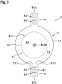
- Fig. 3 shows a cross-sectional cut view of the decompressing unit of Fig. 2 and provides insight on the internal structure of the decompressing unit 3.
- the decompressing unit 3 comprises a first chamber 6, a second chamber 7, and a plurality of optional dampening devices 8.
- the first chamber 6 is configured to receive the pressurized particle conveying fluid stream.
- the first chamber 6 comprises the inlet opening 3.1 of the decompressing unit 3 or can at least directly or indirectly communicate with the inlet opening 3.1 of the decompressing unit 3.
- the first chamber 6 can have a hollow-cylindrical basic shape which defines a central axis A1 of the first chamber 6.
- the first chamber 6 can be built from at least one duct- or pipe-element such that the first chamber 6 can comprise a duct- or pipe-like shape.
- the first chamber 6 is thus, scalable by choosing appropriate duct- or pipe-elements.
- the first chamber 6 comprises or is delimited by a first wall structure 6.1 which defines or delimits a first volume 6.2 which represents the inner volume of the first chamber 6.
- the second chamber 7 surrounds the first chamber 6.
- the second chamber 7 can also have a hollow-cylindrical basic shape which defines a central axis A2 of the second chamber 7.
- the central axis A2 of the second chamber 7 can be coincident with the central axis A1 of the first chamber 6 resulting in a coaxial arrangement (see e.g. Fig. 3 ).
- the second chamber 7 can be built from at least one duct- or pipe-element such that the second chamber 7 can comprise a duct- or pipe-like shape.
- the second chamber 7 is thus, scalable by choosing appropriate duct- or pipe-elements.
- the second chamber 7 comprises or is delimited by a second wall structure 7.1 which defines or delimits a second volume 7.2 which represents the inner volume of the second chamber 7.
- Fig. 2 shows that the decompressing unit 3 can comprise a column-like chamber arrangement.
- Fig. 3 shows the coaxial arrangement of the first and second chamber 6, 7 which is based on that the dimensions, i.e. particularly the inner diameter, of the second chamber 7 are larger than the dimensions, i.e. particularly the outer diameter, of the first chamber 6 such that the second chamber 7 can surround the first chamber 6.
- the first chamber 6 is thus, accommodated in the inner volume of the second chamber 7.
- the first and second chambers 6, 7 are arranged with an angle of approx. 90° relative to a horizontal reference plane P which can be defined by a ground.
- the first and second chambers 6, 7 can be vertically arranged with their respective central axes A1, A2 being oriented approx. 90° relative to the horizontal reference plane P.
- the particles can be conveyed through the decompressing unit 3, i.e. particularly through the first camber 6, e.g. by gravity forces after decompressing the pressurized particle conveying fluid stream as explained above.
- Each dampening device 8 is configured to dampen noise generated through decompressing of the pressurized particle conveying fluid stream via the decompressing unit 3.
- Each dampening device 8 can comprise a housing 8.1 having an inner space 8.2 including a noise dampening structure 8.3 (schematically indicated in Fig. 3 ), e.g. a baffle structure, for dampening noise generated through decompressing of the pressurized particle conveying fluid stream via the decompressing unit 3.
- the noise dampening structure 8.3 can comprise a multi-dimensional arrangement of baffle elements which are positioned and/or oriented to dampen respective noise.
- the housing 8.1 can comprise an inlet 8.1.1 for a fluid stream entering the dampening device 8 and an outlet 8.1.2 for a fluid stream exiting the dampening device 8.
- the noise dampening structure 8.3 is arranged or formed between the inlet 8.1.1 and the outlet 8.1.2.
- Each dampening device 8 can thus, be formed as a sound suppressor device.
- the first wall structure 6.1 comprises a plurality of first openings 6.1.1 through which the inner volume of the first chamber 6 (i.e. the first volume 6.2) is connected with the inner volume of the second chamber 7 (i.e. the second volume 7.2).
- the second wall structure 7.1 comprises a plurality of second openings 7.1.1 through which the inner volume of the second chamber 7 (i.e. the second volume 7.1) is connected with respective dampening devices 8.
- the decompressing unit 3 comprises a specific fluid communication arrangement of the first chamber 6, the second chamber 7, and respective dampening devices 8.
- the first chamber 6 and the second chamber 7 are in fluid communication via respective first openings 6.1.1, which enables that a fluid inside the first chamber 6 can enter the second chamber 7 from the first chamber 6 through the first openings 6.1.1 provided with the first wall structure 6.1.
- the second chamber 7 and the dampening devices i.e. particularly the respective inner space 8.2 including the dampening structure 8.3, are in fluid communication, which enables that a fluid inside the second chamber 7, e.g. a fluid which has entered the second chamber 7 through the first openings 6.1..1, can enter the inner space 8.2 of the dampening devices 8 from the second chamber 7 through the second openings 7.1.1 provided with the second wall structure 7.1.
- the dimensions of the first openings 6.1.1 are typically, small enough to impede that polymer particles within the pressurized particle conveying fluid stream can enter the second chamber 7. Hence, the dimensions of the first openings are typically, at least smaller than the minimum particle size or the mean average particle size of the polymer particles within the pressurized particle conveying fluid stream. As an example, the dimensions of the first openings 6.1.1 can be below 1 mm, particularly below 0,5 mm, more particularly below 0,25 mm.
- the first wall structure 6.1 thus, acts as a separation or screening means configured to separate or screen the polymer particles within the pressurized particle conveying fluid stream from the pressurized particle conveying fluid stream while the pressurized particle conveying fluid stream is decompressed at the same time.
- the first chamber 6 also comprises an inlet opening 6.3 for the pressurized particle conveying fluid stream and an outlet opening 6.4 for the decompressed particle conveying fluid stream.
- the inlet opening 6.3 of the first chamber 6 also represents the inlet opening 3.1 of the decompressing unit 3 and the outlet opening 6.4 of the first chamber 6 also represents the outlet opening 3.2 of the decompressing unit 3.
- An inlet control device 6.5 can be assigned to the inlet opening 6.3.
- the inlet control device 6.5 is configured to control an amount of pressurized particle conveying fluid stream to enter the first chamber 6 via the inlet opening 6.3. Hence, exact control of the amount of pressurized particle conveying fluid stream to enter the first chamber 6 via the inlet opening 6.3 can be determined by the inlet control device 6.5.
- the inlet control device 6.5 comprises a shutter element 6.5.1 moveably supported between at least two orientations and/or positions, wherein at least one first orientation and/or position corresponds to an open state of the inlet control device 6.5 in which an amount of pressurized particle conveying fluid stream can enter the first chamber 6 via the inlet opening 6.3, and at least one second orientation and/or position corresponds to a closed state of the inlet control device 6.5 in which an amount of pressurized particle conveying fluid stream cannot enter the first chamber 6 via the inlet opening 6.3.
- Operation of the inlet control device 6.5 i.e. particularly motions of the shutter element 6.5.1 between respective open and closed states, can be controlled by a hardware- and/or software-embodied control device 13 of the decompressing unit 3 or the apparatus 1, respectively.
- the inlet control device 6.5 can be built as or comprise at least one valve device which comprises at least one valve element (shutter element) moveably supported between at least one open state at least one closed state.
- the valve device can be connected with at least one actuating device (not shown) for actuating the valve element to transfer the valve element between a respective open and closed state and vice versa.
- an outlet control device 6.6 can be assigned to the outlet opening 6.4 of the first chamber 6.
- the outlet control 6.6 device is configured to control an amount of decompressed particle conveying fluid stream and/or the amount of decompressed polymer particles to exit the first chamber 6 via the outlet opening 6.4.
- exact control of the amount of decompressed particle conveying fluid stream and/or the amount of decompressed polymer particles to exit the first chamber 6 via the outlet opening 6.4 can be determined by the outlet control device 6.6.
- the outlet control device 6.6 can comprise a shutter element 6.6.1 moveably supported between at least two orientations and/or positions, wherein at least one first orientation and/or position corresponds to an open state of the outlet control device 6.6.
- outlet control device 6 i.e. particularly motions of the shutter element 6.6.1 between respective open and closed states, can be controlled by the hardware- and/or software-embodied control device 13 of the decompressing unit 3 or the apparatus 1, respectively.
- the outlet control device 6.6 can be built as or comprise at least one valve device which comprises a valve element (shutter element) moveably supported between at least one open state at least one closed state.
- the valve device can be connected with at least one actuating device (not shown) for actuating the valve element to transfer the valve element between a respective open and closed state and vice versa.
- Operation of the inlet control device 6.5 and the outlet control device 6.6 is synchronized via the control device 13. Specifically, when transferring the inlet control device 6.5 in its open state, the outlet control device 6.6 has been previously transferred in its closed state and vice versa. In other words, transferring the inlet control device 6.5 in the open state typically, takes place when the outlet control device 6.6 is in the closed state and vice versa. Hence, synchronizing means that the inlet control device 6.5 and the outlet control 6.6 are never in their respective open state and/or closed state at the same time.
- the first wall structure 6.1 delimiting the first chamber 6 can be built from or comprise a wire wrapped mesh or a wire wrapped screen having a hollow-cylindrical shape which also defines the hollow-cylindrical basic shape of the first chamber 6.
- the first openings 6.1.1 of the first wall structure 6.1 can have varying dimensions, particularly a varying cross-section, between an inlet portion through which a particle conveying fluid stream enters the respective opening 6.1.1 from the first chamber 6 to an outlet portion through which a particle conveying fluid stream exits the respective opening 6.1.1 into the second chamber 7.
- the wall portions of the first wall structure 6.1 delimiting the first openings 6.1.1 can be inclined an auxiliary axis radially extending off the central axis A1 of the first chamber 6.
- the decompressing unit 3 can comprise a plurality of dampening devices 8 located at different positions, e.g. at different axial and/or radial and/or circumferential positions, relative to the circumferential and/or longitudinal extension of the decompressing unit which enables a more homogenous decompression.
- At least two dampening devices 3 disposed at the same axial position, yet at different circumferentially positions, e.g. at opposing circumferential positions, can form a dampening group or dampening stage, respectively.
- the decompressing unit 3 can comprise a plurality of such dampening groups or dampening stages at different axial positions.
- Respective dampening stages can comprise the same number or a different number of dampening devices 8.
- the apparatus 1 can comprise a cleaning fluid stream generating unit for generating a pressurized cleaning fluid stream for cleaning the decompressing unit 3 from residue polymer particles.
- the cleaning stream particularly, serves for cleaning the first chamber 6 from particle residues which have not been removed through a respective outlet opening 6.4 of the first chamber 6.
- the cleaning stream can serve for cleaning respective connecting means connecting the pressurizing unit 2 and the decompressing unit 3.
- the cleaning fluid stream generating unit can be identical with the pressurizing unit 2.
- the pressurizing unit 2 can also be configured to generate a respective cleaning fluid stream which does not comprise polymer particles to be conveyed.
- the cleaning fluid stream can also be a gas stream, such as an air stream or an inert gas stream.
- the apparatus 1 can be operated in a cleaning mode in which residue polymer particles can be removed from the decompressing unit 3.
- operation of the inlet control device 6.5 and the outlet control device 6.6 is typically, synchronized via a respective hardware- and/or software-embodied control device of the inlet control device 6.5 and the outlet control device 6.6 or via a superordinate hardware- and/or software-embodied control device of the decompressing unit 3 or the apparatus 1, respectively.
- both the inlet control device 6.5 and the outlet control device 6.6 are transferred in their respective open state.
- synchronizing in the cleaning mode typically, means that the inlet control device 6.5 and the outlet control device 6.6 are both in their respective open state at the same time.
- a respective cleaning mode can be initiated with a master key, e.g. a mechanical master key, configured to initiate a controlled synchronization of the inlet control device 6.5 and the outlet control device 6.6 such that they are transferred in their respective open state.
- a master key e.g. a mechanical master key
- Fig. 2 also shows that the apparatus 1 can comprise a support structure 9 for supporting at least the decompressing unit 3 in a desired orientation and/or position.
- a respective support structure 9 can support at least the decompressing unit 3 in a vertical orientation and/or position, i.e. particularly an orientation and/or position in which the first and second chambers 6, 7 are vertically arranged with their respective central axes A1, A2 being oriented approx. 90° relative a horizontal reference plane.
- At least the first and second chamber 6, 7 can be arranged in a housing structure of the apparatus 1 which can protect them e.g. from environmental influences.
- the apparatus 1 can form part of a superordinate system 10 for processing polymer particles, particularly for post-processing of polymer particles.
- the system 10 comprises at least one storage apparatus 11 for storing polymer particles to be processed via at least one processing apparatus 12, such as a molding apparatus for molding a polymer part, at least one processing apparatus 12 for processing polymer particles, and the apparatus 1.
- the apparatus 1 also enables implementing a method for conveying polymer particles from a first location L1 to a second location L2.
- the method comprises the steps of: generating, via a pressurizing unit 2, a particle conveying fluid stream, particularly comprising polymer particles in a pressurized fluid, the pressurized particle conveying fluid stream having a first pressure level; and decompressing, via a decompressing unit 3, the pressurized particle conveying fluid stream from the first pressure level to generate a decompressed particle conveying fluid stream having a second pressure level.
- the decompressing unit 3 used in the method comprises a first chamber 6 for receiving the pressurized particle conveying fluid stream, a second chamber 7 surrounding the first chamber 7, and optionally at least one dampening device 8 for dampening noise generated through decompression of the pressurized particle conveying fluid stream via the decompressing unit 3, wherein the first chamber 6 is delimited by a first wall structure 6.1 and the second chamber 7 is delimited by a second wall structure 7.1; wherein the first wall structure 6.1 comprises at least one first opening 6.1.1 through which an inner volume of the first chamber 6 is connected with an inner volume of the second chamber 7 and the second wall structure 7.1 comprises at least one second opening 7.1.1 through which the inner volume of the second chamber 7 is connected with at least one dampening device 8.
Landscapes
- Engineering & Computer Science (AREA)
- Mechanical Engineering (AREA)
- Chemical & Material Sciences (AREA)
- Organic Chemistry (AREA)
- Chemical Kinetics & Catalysis (AREA)
- Feeding, Discharge, Calcimining, Fusing, And Gas-Generation Devices (AREA)
- Processing And Handling Of Plastics And Other Materials For Molding In General (AREA)
- Air Transport Of Granular Materials (AREA)
Priority Applications (6)
| Application Number | Priority Date | Filing Date | Title |
|---|---|---|---|
| EP22150679.3A EP4209436B1 (fr) | 2022-01-10 | 2022-01-10 | Appareil de transport de particules de polymères |
| PCT/EP2023/050305 WO2023131704A1 (fr) | 2022-01-10 | 2023-01-09 | Unité de décompression pour un appareil de transport de particules polymères |
| KR1020247023672A KR20240134897A (ko) | 2022-01-10 | 2023-01-09 | 중합체 입자를 운반하기 위한 장치를 위한 감압 유닛 |
| US18/727,284 US20250100815A1 (en) | 2022-01-10 | 2023-01-09 | Decompressing unit for an apparatus for conveying polymer particles |
| JP2024541162A JP2025501660A (ja) | 2022-01-10 | 2023-01-09 | ポリマー粒子搬送用装置 |
| CN202380016802.9A CN118541322A (zh) | 2022-01-10 | 2023-01-09 | 用于输送聚合物颗粒的设备的减压单元 |
Applications Claiming Priority (1)
| Application Number | Priority Date | Filing Date | Title |
|---|---|---|---|
| EP22150679.3A EP4209436B1 (fr) | 2022-01-10 | 2022-01-10 | Appareil de transport de particules de polymères |
Publications (2)
| Publication Number | Publication Date |
|---|---|
| EP4209436A1 true EP4209436A1 (fr) | 2023-07-12 |
| EP4209436B1 EP4209436B1 (fr) | 2024-05-22 |
Family
ID=80218699
Family Applications (1)
| Application Number | Title | Priority Date | Filing Date |
|---|---|---|---|
| EP22150679.3A Active EP4209436B1 (fr) | 2022-01-10 | 2022-01-10 | Appareil de transport de particules de polymères |
Country Status (6)
| Country | Link |
|---|---|
| US (1) | US20250100815A1 (fr) |
| EP (1) | EP4209436B1 (fr) |
| JP (1) | JP2025501660A (fr) |
| KR (1) | KR20240134897A (fr) |
| CN (1) | CN118541322A (fr) |
| WO (1) | WO2023131704A1 (fr) |
Families Citing this family (1)
| Publication number | Priority date | Publication date | Assignee | Title |
|---|---|---|---|---|
| EP4209263A1 (fr) * | 2022-01-10 | 2023-07-12 | JSP International SARL | Appareil de transport de particules de polyoléfine |
Citations (1)
| Publication number | Priority date | Publication date | Assignee | Title |
|---|---|---|---|---|
| US4082366A (en) * | 1977-03-18 | 1978-04-04 | General Motors Corporation | Feeding apparatus for lightweight plastic particles into a high pressure reactor |
Family Cites Families (25)
| Publication number | Priority date | Publication date | Assignee | Title |
|---|---|---|---|---|
| US1355444A (en) * | 1918-04-27 | 1920-10-12 | Milton W Arrowood | Method and means for feeding powdered fuel |
| US3297466A (en) * | 1962-11-01 | 1967-01-10 | Nat Lead Co | Continuous process for encapsulating individual particles of particulate material with a polyolefin |
| US3436344A (en) * | 1963-11-27 | 1969-04-01 | American Potash & Chem Corp | Process for removing impurities from a fluid stream |
| US3992282A (en) * | 1973-05-24 | 1976-11-16 | Atlantic Richfield Company | Method contacting a bed of solid particles with a stream containing particulate impurities |
| US4198860A (en) * | 1978-02-27 | 1980-04-22 | Phillips Petroleum Company | Method and apparatus for measuring particulate matter flow rate |
| US5160513A (en) * | 1991-11-13 | 1992-11-03 | Uop | Inlet stream debris collection method and apparatus |
| US5657704A (en) * | 1996-01-23 | 1997-08-19 | The Babcock & Wilcox Company | Continuous high pressure solids pump system |
| AUPP789898A0 (en) * | 1998-12-23 | 1999-01-21 | Birrus Engineering Pty Ltd | Conveying |
| US7524904B2 (en) * | 2002-09-16 | 2009-04-28 | Chevron Phillips Chemical Company Lp | Process and apparatus for separating polymer solids, hydrocarbon fluids, and purge gas |
| DE10317533A1 (de) * | 2003-04-16 | 2004-11-04 | Basell Polyolefine Gmbh | Verfahren zur diskontinuierlichen Katalysatordosierung in einen Gasphasenwirbelschichtreaktor |
| US7648566B2 (en) * | 2006-11-09 | 2010-01-19 | General Electric Company | Methods and apparatus for carbon dioxide removal from a fluid stream |
| US7871460B2 (en) * | 2007-02-23 | 2011-01-18 | Tw Environmental, Inc. | System and method for a moving bed adsorber for contaminant removal |
| US8061413B2 (en) * | 2007-09-13 | 2011-11-22 | Battelle Energy Alliance, Llc | Heat exchangers comprising at least one porous member positioned within a casing |
| WO2011053704A1 (fr) * | 2009-10-28 | 2011-05-05 | Conocophillips Company-Ip Services Group | Filtre à lit catalytique mobile |
| US8950570B2 (en) * | 2009-12-15 | 2015-02-10 | Exxonmobil Research And Engineering Company | Passive solids supply system and method for supplying solids |
| EP2348056A1 (fr) * | 2010-01-26 | 2011-07-27 | Ineos Europe Limited | Procédé pour la polyménisation d'oléfines en phase gaz |
| EP2579963A1 (fr) * | 2010-06-09 | 2013-04-17 | Cormetech, Inc. | Dispositif et procédés de traitement des gaz d'échappement |
| US8882400B2 (en) * | 2010-10-29 | 2014-11-11 | General Electric Company | Solids feeder discharge port |
| BR112013010886A2 (pt) * | 2010-11-05 | 2016-08-02 | Thermochem Recovery Int Inc | sistema de circulação de sólidos e processo para captura e conversão de sólidos reativos |
| BR112017011989B8 (pt) * | 2015-01-09 | 2022-02-22 | Exxonmobil Upstream Res Co | Separar impurezas de uma corrente de fluido usando contatores em co-corrente múltiplos |
| WO2019231398A1 (fr) * | 2018-06-01 | 2019-12-05 | Mobiair Pte. Ltd. | Appareil et procédé pour nettoyer un fluide chargé de particules à l'aide d'une technologie de diviseur multi-flux à faible énergie ne nécessitant pas de milieu filtrant |
| US12059648B2 (en) * | 2021-02-05 | 2024-08-13 | Ge Infrastructure Technology Llc | Carbon dioxide capture system and method of capturing carbon dioxide |
| HUE071339T2 (hu) * | 2021-04-30 | 2025-08-28 | Jsp Int Sarl | Eljárás cellás poliolefin-alapú mûanyagrészecskék elõállítására |
| DE102021111249A1 (de) * | 2021-04-30 | 2022-11-03 | Fox Velution Gmbh | Verfahren zur Herstellung zellulärer Kunststoffpartikel |
| DE102021111247A1 (de) * | 2021-04-30 | 2022-11-03 | Fox Velution Gmbh | Verfahren zur Herstellung zellulärer Kunststoffpartikel |
-
2022
- 2022-01-10 EP EP22150679.3A patent/EP4209436B1/fr active Active
-
2023
- 2023-01-09 CN CN202380016802.9A patent/CN118541322A/zh active Pending
- 2023-01-09 US US18/727,284 patent/US20250100815A1/en active Pending
- 2023-01-09 JP JP2024541162A patent/JP2025501660A/ja active Pending
- 2023-01-09 KR KR1020247023672A patent/KR20240134897A/ko active Pending
- 2023-01-09 WO PCT/EP2023/050305 patent/WO2023131704A1/fr not_active Ceased
Patent Citations (1)
| Publication number | Priority date | Publication date | Assignee | Title |
|---|---|---|---|---|
| US4082366A (en) * | 1977-03-18 | 1978-04-04 | General Motors Corporation | Feeding apparatus for lightweight plastic particles into a high pressure reactor |
Also Published As
| Publication number | Publication date |
|---|---|
| JP2025501660A (ja) | 2025-01-22 |
| US20250100815A1 (en) | 2025-03-27 |
| WO2023131704A1 (fr) | 2023-07-13 |
| EP4209436B1 (fr) | 2024-05-22 |
| CN118541322A (zh) | 2024-08-23 |
| KR20240134897A (ko) | 2024-09-10 |
Similar Documents
| Publication | Publication Date | Title |
|---|---|---|
| US20250100815A1 (en) | Decompressing unit for an apparatus for conveying polymer particles | |
| US8851113B2 (en) | Shared gas panels in plasma processing systems | |
| CA2963948C (fr) | Resonateurs concentriques pour machines | |
| KR20100038382A (ko) | 반도체 웨이퍼 수납용기 내로의 드라이에어 또는 질소가스 충전 장치 및 그 장치를 이용한 웨이퍼 정전 제거장치 | |
| EP4209263A1 (fr) | Appareil de transport de particules de polyoléfine | |
| US20140138462A1 (en) | Jet milling of boron powder using inert gases to meet purity requirements | |
| JP2009523015A5 (fr) | ||
| KR101741283B1 (ko) | 베벨 에칭 적용에서 개선된 유체 전달을 위한 장치 및 방법 | |
| JP2025501660A5 (fr) | ||
| CN111947450A (zh) | 半导体腔室及退火装置 | |
| JP3242937U (ja) | ターゲット球体スクリーニング装置 | |
| US20160180829A1 (en) | Noise reducing device | |
| US6723172B2 (en) | Method and system for processing semiconductor wafers | |
| JP2025518226A (ja) | 真空処理システムの排ガスを処理するための除害システム | |
| RU2405063C2 (ru) | Реактор | |
| US12615987B2 (en) | Substrate processing apparatus and system including the same | |
| CN214464748U (zh) | 一种气体脉冲缓冲装置 | |
| Michelato et al. | INFN Milano–LASA activities for ESS | |
| JP2000195806A (ja) | 半導体プロセスガス用バルク供給装置とこれを使用したガス供給方法 | |
| JP2025520921A5 (fr) | ||
| KR101320925B1 (ko) | 반도체 제조장치의 진공압 측정용 앵글밸브 | |
| KR20190099829A (ko) | 백필터용 탈진장치 및 이를 포함하는 집진기 | |
| WO2016075048A1 (fr) | Dispositif pour amortir les pulsations de pression dans un flux de gaz | |
| TWI519671B (zh) | 氣體傳輸裝置及方法 | |
| TW202409420A (zh) | 用於真空泵送系統之流體選徑輸送 |
Legal Events
| Date | Code | Title | Description |
|---|---|---|---|
| PUAI | Public reference made under article 153(3) epc to a published international application that has entered the european phase |
Free format text: ORIGINAL CODE: 0009012 |
|
| STAA | Information on the status of an ep patent application or granted ep patent |
Free format text: STATUS: THE APPLICATION HAS BEEN PUBLISHED |
|
| AK | Designated contracting states |
Kind code of ref document: A1 Designated state(s): AL AT BE BG CH CY CZ DE DK EE ES FI FR GB GR HR HU IE IS IT LI LT LU LV MC MK MT NL NO PL PT RO RS SE SI SK SM TR |
|
| RAP3 | Party data changed (applicant data changed or rights of an application transferred) |
Owner name: FOX VELUTION GMBH |
|
| STAA | Information on the status of an ep patent application or granted ep patent |
Free format text: STATUS: REQUEST FOR EXAMINATION WAS MADE |
|
| 17P | Request for examination filed |
Effective date: 20240110 |
|
| RBV | Designated contracting states (corrected) |
Designated state(s): AL AT BE BG CH CY CZ DE DK EE ES FI FR GB GR HR HU IE IS IT LI LT LU LV MC MK MT NL NO PL PT RO RS SE SI SK SM TR |
|
| GRAP | Despatch of communication of intention to grant a patent |
Free format text: ORIGINAL CODE: EPIDOSNIGR1 |
|
| STAA | Information on the status of an ep patent application or granted ep patent |
Free format text: STATUS: GRANT OF PATENT IS INTENDED |
|
| GRAS | Grant fee paid |
Free format text: ORIGINAL CODE: EPIDOSNIGR3 |
|
| GRAA | (expected) grant |
Free format text: ORIGINAL CODE: 0009210 |
|
| STAA | Information on the status of an ep patent application or granted ep patent |
Free format text: STATUS: THE PATENT HAS BEEN GRANTED |
|
| INTG | Intention to grant announced |
Effective date: 20240409 |
|
| AK | Designated contracting states |
Kind code of ref document: B1 Designated state(s): AL AT BE BG CH CY CZ DE DK EE ES FI FR GB GR HR HU IE IS IT LI LT LU LV MC MK MT NL NO PL PT RO RS SE SI SK SM TR |
|
| REG | Reference to a national code |
Ref country code: GB Ref legal event code: FG4D |
|
| REG | Reference to a national code |
Ref country code: CH Ref legal event code: EP |
|
| REG | Reference to a national code |
Ref country code: DE Ref legal event code: R096 Ref document number: 602022003516 Country of ref document: DE |
|
| REG | Reference to a national code |
Ref country code: IE Ref legal event code: FG4D |
|
| REG | Reference to a national code |
Ref country code: NL Ref legal event code: FP |
|
| REG | Reference to a national code |
Ref country code: LT Ref legal event code: MG9D |
|
| P01 | Opt-out of the competence of the unified patent court (upc) registered |
Free format text: CASE NUMBER: APP_47598/2024 Effective date: 20240819 |
|
| PG25 | Lapsed in a contracting state [announced via postgrant information from national office to epo] |
Ref country code: IS Free format text: LAPSE BECAUSE OF FAILURE TO SUBMIT A TRANSLATION OF THE DESCRIPTION OR TO PAY THE FEE WITHIN THE PRESCRIBED TIME-LIMIT Effective date: 20240922 |
|
| PG25 | Lapsed in a contracting state [announced via postgrant information from national office to epo] |
Ref country code: BG Free format text: LAPSE BECAUSE OF FAILURE TO SUBMIT A TRANSLATION OF THE DESCRIPTION OR TO PAY THE FEE WITHIN THE PRESCRIBED TIME-LIMIT Effective date: 20240522 |
|
| PG25 | Lapsed in a contracting state [announced via postgrant information from national office to epo] |
Ref country code: HR Free format text: LAPSE BECAUSE OF FAILURE TO SUBMIT A TRANSLATION OF THE DESCRIPTION OR TO PAY THE FEE WITHIN THE PRESCRIBED TIME-LIMIT Effective date: 20240522 Ref country code: FI Free format text: LAPSE BECAUSE OF FAILURE TO SUBMIT A TRANSLATION OF THE DESCRIPTION OR TO PAY THE FEE WITHIN THE PRESCRIBED TIME-LIMIT Effective date: 20240522 |
|
| PG25 | Lapsed in a contracting state [announced via postgrant information from national office to epo] |
Ref country code: GR Free format text: LAPSE BECAUSE OF FAILURE TO SUBMIT A TRANSLATION OF THE DESCRIPTION OR TO PAY THE FEE WITHIN THE PRESCRIBED TIME-LIMIT Effective date: 20240823 |
|
| PG25 | Lapsed in a contracting state [announced via postgrant information from national office to epo] |
Ref country code: PT Free format text: LAPSE BECAUSE OF FAILURE TO SUBMIT A TRANSLATION OF THE DESCRIPTION OR TO PAY THE FEE WITHIN THE PRESCRIBED TIME-LIMIT Effective date: 20240923 |
|
| PG25 | Lapsed in a contracting state [announced via postgrant information from national office to epo] |
Ref country code: ES Free format text: LAPSE BECAUSE OF FAILURE TO SUBMIT A TRANSLATION OF THE DESCRIPTION OR TO PAY THE FEE WITHIN THE PRESCRIBED TIME-LIMIT Effective date: 20240522 |
|
| PG25 | Lapsed in a contracting state [announced via postgrant information from national office to epo] |
Ref country code: PL Free format text: LAPSE BECAUSE OF FAILURE TO SUBMIT A TRANSLATION OF THE DESCRIPTION OR TO PAY THE FEE WITHIN THE PRESCRIBED TIME-LIMIT Effective date: 20240522 |
|
| PG25 | Lapsed in a contracting state [announced via postgrant information from national office to epo] |
Ref country code: LV Free format text: LAPSE BECAUSE OF FAILURE TO SUBMIT A TRANSLATION OF THE DESCRIPTION OR TO PAY THE FEE WITHIN THE PRESCRIBED TIME-LIMIT Effective date: 20240522 |
|
| PG25 | Lapsed in a contracting state [announced via postgrant information from national office to epo] |
Ref country code: PT Free format text: LAPSE BECAUSE OF FAILURE TO SUBMIT A TRANSLATION OF THE DESCRIPTION OR TO PAY THE FEE WITHIN THE PRESCRIBED TIME-LIMIT Effective date: 20240923 Ref country code: PL Free format text: LAPSE BECAUSE OF FAILURE TO SUBMIT A TRANSLATION OF THE DESCRIPTION OR TO PAY THE FEE WITHIN THE PRESCRIBED TIME-LIMIT Effective date: 20240522 Ref country code: NO Free format text: LAPSE BECAUSE OF FAILURE TO SUBMIT A TRANSLATION OF THE DESCRIPTION OR TO PAY THE FEE WITHIN THE PRESCRIBED TIME-LIMIT Effective date: 20240822 Ref country code: LV Free format text: LAPSE BECAUSE OF FAILURE TO SUBMIT A TRANSLATION OF THE DESCRIPTION OR TO PAY THE FEE WITHIN THE PRESCRIBED TIME-LIMIT Effective date: 20240522 Ref country code: IS Free format text: LAPSE BECAUSE OF FAILURE TO SUBMIT A TRANSLATION OF THE DESCRIPTION OR TO PAY THE FEE WITHIN THE PRESCRIBED TIME-LIMIT Effective date: 20240922 Ref country code: HR Free format text: LAPSE BECAUSE OF FAILURE TO SUBMIT A TRANSLATION OF THE DESCRIPTION OR TO PAY THE FEE WITHIN THE PRESCRIBED TIME-LIMIT Effective date: 20240522 Ref country code: GR Free format text: LAPSE BECAUSE OF FAILURE TO SUBMIT A TRANSLATION OF THE DESCRIPTION OR TO PAY THE FEE WITHIN THE PRESCRIBED TIME-LIMIT Effective date: 20240823 Ref country code: FI Free format text: LAPSE BECAUSE OF FAILURE TO SUBMIT A TRANSLATION OF THE DESCRIPTION OR TO PAY THE FEE WITHIN THE PRESCRIBED TIME-LIMIT Effective date: 20240522 Ref country code: ES Free format text: LAPSE BECAUSE OF FAILURE TO SUBMIT A TRANSLATION OF THE DESCRIPTION OR TO PAY THE FEE WITHIN THE PRESCRIBED TIME-LIMIT Effective date: 20240522 Ref country code: BG Free format text: LAPSE BECAUSE OF FAILURE TO SUBMIT A TRANSLATION OF THE DESCRIPTION OR TO PAY THE FEE WITHIN THE PRESCRIBED TIME-LIMIT Effective date: 20240522 Ref country code: RS Free format text: LAPSE BECAUSE OF FAILURE TO SUBMIT A TRANSLATION OF THE DESCRIPTION OR TO PAY THE FEE WITHIN THE PRESCRIBED TIME-LIMIT Effective date: 20240822 |
|
| PG25 | Lapsed in a contracting state [announced via postgrant information from national office to epo] |
Ref country code: DK Free format text: LAPSE BECAUSE OF FAILURE TO SUBMIT A TRANSLATION OF THE DESCRIPTION OR TO PAY THE FEE WITHIN THE PRESCRIBED TIME-LIMIT Effective date: 20240522 |
|
| PG25 | Lapsed in a contracting state [announced via postgrant information from national office to epo] |
Ref country code: EE Free format text: LAPSE BECAUSE OF FAILURE TO SUBMIT A TRANSLATION OF THE DESCRIPTION OR TO PAY THE FEE WITHIN THE PRESCRIBED TIME-LIMIT Effective date: 20240522 |
|
| PG25 | Lapsed in a contracting state [announced via postgrant information from national office to epo] |
Ref country code: CZ Free format text: LAPSE BECAUSE OF FAILURE TO SUBMIT A TRANSLATION OF THE DESCRIPTION OR TO PAY THE FEE WITHIN THE PRESCRIBED TIME-LIMIT Effective date: 20240522 |
|
| PG25 | Lapsed in a contracting state [announced via postgrant information from national office to epo] |
Ref country code: RO Free format text: LAPSE BECAUSE OF FAILURE TO SUBMIT A TRANSLATION OF THE DESCRIPTION OR TO PAY THE FEE WITHIN THE PRESCRIBED TIME-LIMIT Effective date: 20240522 Ref country code: SK Free format text: LAPSE BECAUSE OF FAILURE TO SUBMIT A TRANSLATION OF THE DESCRIPTION OR TO PAY THE FEE WITHIN THE PRESCRIBED TIME-LIMIT Effective date: 20240522 |
|
| PG25 | Lapsed in a contracting state [announced via postgrant information from national office to epo] |
Ref country code: SK Free format text: LAPSE BECAUSE OF FAILURE TO SUBMIT A TRANSLATION OF THE DESCRIPTION OR TO PAY THE FEE WITHIN THE PRESCRIBED TIME-LIMIT Effective date: 20240522 Ref country code: RO Free format text: LAPSE BECAUSE OF FAILURE TO SUBMIT A TRANSLATION OF THE DESCRIPTION OR TO PAY THE FEE WITHIN THE PRESCRIBED TIME-LIMIT Effective date: 20240522 Ref country code: EE Free format text: LAPSE BECAUSE OF FAILURE TO SUBMIT A TRANSLATION OF THE DESCRIPTION OR TO PAY THE FEE WITHIN THE PRESCRIBED TIME-LIMIT Effective date: 20240522 Ref country code: DK Free format text: LAPSE BECAUSE OF FAILURE TO SUBMIT A TRANSLATION OF THE DESCRIPTION OR TO PAY THE FEE WITHIN THE PRESCRIBED TIME-LIMIT Effective date: 20240522 Ref country code: CZ Free format text: LAPSE BECAUSE OF FAILURE TO SUBMIT A TRANSLATION OF THE DESCRIPTION OR TO PAY THE FEE WITHIN THE PRESCRIBED TIME-LIMIT Effective date: 20240522 |
|
| REG | Reference to a national code |
Ref country code: DE Ref legal event code: R097 Ref document number: 602022003516 Country of ref document: DE |
|
| PLBE | No opposition filed within time limit |
Free format text: ORIGINAL CODE: 0009261 |
|
| STAA | Information on the status of an ep patent application or granted ep patent |
Free format text: STATUS: NO OPPOSITION FILED WITHIN TIME LIMIT |
|
| PG25 | Lapsed in a contracting state [announced via postgrant information from national office to epo] |
Ref country code: SI Free format text: LAPSE BECAUSE OF FAILURE TO SUBMIT A TRANSLATION OF THE DESCRIPTION OR TO PAY THE FEE WITHIN THE PRESCRIBED TIME-LIMIT Effective date: 20240522 |
|
| 26N | No opposition filed |
Effective date: 20250225 |
|
| REG | Reference to a national code |
Ref country code: CH Ref legal event code: PL |
|
| PG25 | Lapsed in a contracting state [announced via postgrant information from national office to epo] |
Ref country code: SE Free format text: LAPSE BECAUSE OF FAILURE TO SUBMIT A TRANSLATION OF THE DESCRIPTION OR TO PAY THE FEE WITHIN THE PRESCRIBED TIME-LIMIT Effective date: 20240522 |
|
| PG25 | Lapsed in a contracting state [announced via postgrant information from national office to epo] |
Ref country code: LU Free format text: LAPSE BECAUSE OF NON-PAYMENT OF DUE FEES Effective date: 20250110 Ref country code: MC Free format text: LAPSE BECAUSE OF FAILURE TO SUBMIT A TRANSLATION OF THE DESCRIPTION OR TO PAY THE FEE WITHIN THE PRESCRIBED TIME-LIMIT Effective date: 20240522 |
|
| REG | Reference to a national code |
Ref country code: AT Ref legal event code: UEP Ref document number: 1688631 Country of ref document: AT Kind code of ref document: T Effective date: 20240522 |
|
| PG25 | Lapsed in a contracting state [announced via postgrant information from national office to epo] |
Ref country code: BE Free format text: LAPSE BECAUSE OF NON-PAYMENT OF DUE FEES Effective date: 20250131 |
|
| PG25 | Lapsed in a contracting state [announced via postgrant information from national office to epo] |
Ref country code: CH Free format text: LAPSE BECAUSE OF NON-PAYMENT OF DUE FEES Effective date: 20250131 |
|
| REG | Reference to a national code |
Ref country code: BE Ref legal event code: MM Effective date: 20250131 |
|
| PG25 | Lapsed in a contracting state [announced via postgrant information from national office to epo] |
Ref country code: IE Free format text: LAPSE BECAUSE OF NON-PAYMENT OF DUE FEES Effective date: 20250110 |
|
| PGFP | Annual fee paid to national office [announced via postgrant information from national office to epo] |
Ref country code: NL Payment date: 20260129 Year of fee payment: 5 |
|
| PGFP | Annual fee paid to national office [announced via postgrant information from national office to epo] |
Ref country code: DE Payment date: 20260128 Year of fee payment: 5 |
|
| PGFP | Annual fee paid to national office [announced via postgrant information from national office to epo] |
Ref country code: AT Payment date: 20260301 Year of fee payment: 5 |
|
| PGFP | Annual fee paid to national office [announced via postgrant information from national office to epo] |
Ref country code: IT Payment date: 20260130 Year of fee payment: 5 |
|
| PGFP | Annual fee paid to national office [announced via postgrant information from national office to epo] |
Ref country code: FR Payment date: 20260129 Year of fee payment: 5 |