EP4209574A1 - Temperaturregelvorrichtung - Google Patents
Temperaturregelvorrichtung Download PDFInfo
- Publication number
- EP4209574A1 EP4209574A1 EP20952418.0A EP20952418A EP4209574A1 EP 4209574 A1 EP4209574 A1 EP 4209574A1 EP 20952418 A EP20952418 A EP 20952418A EP 4209574 A1 EP4209574 A1 EP 4209574A1
- Authority
- EP
- European Patent Office
- Prior art keywords
- temperature regulating
- regulating block
- temperature
- control device
- hollow parts
- Prior art date
- Legal status (The legal status is an assumption and is not a legal conclusion. Google has not performed a legal analysis and makes no representation as to the accuracy of the status listed.)
- Pending
Links
Images




Classifications
-
- B—PERFORMING OPERATIONS; TRANSPORTING
- B01—PHYSICAL OR CHEMICAL PROCESSES OR APPARATUS IN GENERAL
- B01L—CHEMICAL OR PHYSICAL LABORATORY APPARATUS FOR GENERAL USE
- B01L7/00—Heating or cooling apparatus; Heat insulating devices
- B01L7/52—Heating or cooling apparatus; Heat insulating devices with provision for submitting samples to a predetermined sequence of different temperatures, e.g. for treating nucleic acid samples
-
- C—CHEMISTRY; METALLURGY
- C12—BIOCHEMISTRY; BEER; SPIRITS; WINE; VINEGAR; MICROBIOLOGY; ENZYMOLOGY; MUTATION OR GENETIC ENGINEERING
- C12M—APPARATUS FOR ENZYMOLOGY OR MICROBIOLOGY; APPARATUS FOR CULTURING MICROORGANISMS FOR PRODUCING BIOMASS, FOR GROWING CELLS OR FOR OBTAINING FERMENTATION OR METABOLIC PRODUCTS, i.e. BIOREACTORS OR FERMENTERS
- C12M41/00—Means for regulation, monitoring, measurement or control, e.g. flow regulation
- C12M41/12—Means for regulation, monitoring, measurement or control, e.g. flow regulation of temperature
-
- C—CHEMISTRY; METALLURGY
- C12—BIOCHEMISTRY; BEER; SPIRITS; WINE; VINEGAR; MICROBIOLOGY; ENZYMOLOGY; MUTATION OR GENETIC ENGINEERING
- C12M—APPARATUS FOR ENZYMOLOGY OR MICROBIOLOGY; APPARATUS FOR CULTURING MICROORGANISMS FOR PRODUCING BIOMASS, FOR GROWING CELLS OR FOR OBTAINING FERMENTATION OR METABOLIC PRODUCTS, i.e. BIOREACTORS OR FERMENTERS
- C12M1/00—Apparatus for enzymology or microbiology
-
- C—CHEMISTRY; METALLURGY
- C12—BIOCHEMISTRY; BEER; SPIRITS; WINE; VINEGAR; MICROBIOLOGY; ENZYMOLOGY; MUTATION OR GENETIC ENGINEERING
- C12Q—MEASURING OR TESTING PROCESSES INVOLVING ENZYMES, NUCLEIC ACIDS OR MICROORGANISMS; COMPOSITIONS OR TEST PAPERS THEREFOR; PROCESSES OF PREPARING SUCH COMPOSITIONS; CONDITION-RESPONSIVE CONTROL IN MICROBIOLOGICAL OR ENZYMOLOGICAL PROCESSES
- C12Q1/00—Measuring or testing processes involving enzymes, nucleic acids or microorganisms; Compositions therefor; Processes of preparing such compositions
- C12Q1/68—Measuring or testing processes involving enzymes, nucleic acids or microorganisms; Compositions therefor; Processes of preparing such compositions involving nucleic acids
- C12Q1/6844—Nucleic acid amplification reactions
- C12Q1/686—Polymerase chain reaction [PCR]
-
- B—PERFORMING OPERATIONS; TRANSPORTING
- B01—PHYSICAL OR CHEMICAL PROCESSES OR APPARATUS IN GENERAL
- B01L—CHEMICAL OR PHYSICAL LABORATORY APPARATUS FOR GENERAL USE
- B01L2200/00—Solutions for specific problems relating to chemical or physical laboratory apparatus
- B01L2200/02—Adapting objects or devices to another
- B01L2200/025—Align devices or objects to ensure defined positions relative to each other
-
- B—PERFORMING OPERATIONS; TRANSPORTING
- B01—PHYSICAL OR CHEMICAL PROCESSES OR APPARATUS IN GENERAL
- B01L—CHEMICAL OR PHYSICAL LABORATORY APPARATUS FOR GENERAL USE
- B01L2200/00—Solutions for specific problems relating to chemical or physical laboratory apparatus
- B01L2200/14—Process control and prevention of errors
- B01L2200/143—Quality control, feedback systems
- B01L2200/147—Employing temperature sensors
-
- B—PERFORMING OPERATIONS; TRANSPORTING
- B01—PHYSICAL OR CHEMICAL PROCESSES OR APPARATUS IN GENERAL
- B01L—CHEMICAL OR PHYSICAL LABORATORY APPARATUS FOR GENERAL USE
- B01L2300/00—Additional constructional details
- B01L2300/08—Geometry, shape and general structure
- B01L2300/0861—Configuration of multiple channels and/or chambers in a single devices
-
- B—PERFORMING OPERATIONS; TRANSPORTING
- B01—PHYSICAL OR CHEMICAL PROCESSES OR APPARATUS IN GENERAL
- B01L—CHEMICAL OR PHYSICAL LABORATORY APPARATUS FOR GENERAL USE
- B01L2300/00—Additional constructional details
- B01L2300/18—Means for temperature control
- B01L2300/1805—Conductive heating, heat from thermostatted solids is conducted to receptacles, e.g. heating plates, blocks
- B01L2300/1822—Conductive heating, heat from thermostatted solids is conducted to receptacles, e.g. heating plates, blocks using Peltier elements
Definitions
- the present invention relates to a temperature control device.
- genetic testing has come to be used not only in research applications but also in a wide range of applications such as personalized medical care and identification to identify an individual, and it is desired not only to improve the accuracy but also to shorten a test time.
- a sample containing DNA (Deoxyribonucleic acid) is acquired, and then a trace amount of DNA in the sample is amplified and then analyzed. In this manner, a highly accurate test is performed.
- a PCR Polymerase Chain Reaction
- a sample solution containing DNA and a solution containing a reagent for amplifying DNA are mixed, and for example, DNA is denatured into a single strand at 94°C, and a complementary strand is synthesized at 60°C. By repeating such temperature changes, DNA can be amplified exponentially by the PCR method.
- a general temperature control device includes a temperature regulating element such as a Peltier element that controls a temperature change, and a temperature regulating block (also referred to as a "temperature regulating block” below) provided to be in contact with the temperature regulating element.
- a temperature control device performs the PCR method by holding a reaction container accommodating a reaction solution in the temperature regulating block, and controlling the temperature of the temperature regulating block with the temperature regulating element.
- the thermal conductivity and the heat capacity of the temperature regulating block affect the speed-up of the temperature change of the reaction solution in the temperature control device.
- a material having a high thermal conductivity for example, metal such as aluminum or copper is used for the temperature regulating block.
- the heat capacity is a value obtained from the specific heat, density, and volume of the material.
- thermocycling device disclosed in PTL 1 includes a sample holder, a thermal reference, and a heat sink, and one or a plurality of the sample holder, the thermal reference, and the heat sink has a material having a high thermal conductivity.
- the multiple sample support disclosed in PTL 2 includes a block having a single structure, a series of sample wells in the block, and a series of hollow parts in the block, which are provided between the sample wells. The mass of the block is reduced by the hollow part, and the temperature change is transferred to the sample quickly.
- the temperature control device When the temperature control device performs the genetic testing, if the temperature of the temperature regulating block is not appropriately controlled and the reaction solution containing the sample and the reagent is not controlled to an appropriate temperature, it is not possible to stably amplify DNA, and the reliability of the genetic testing is lowered.
- the temperature regulating block generally, if the thermal conductivity is small even though the heat capacity is small, it is not possible to uniformly transfer the heat of the temperature regulating element to the reaction solution, and it is difficult to control the reaction solution to a temperature obtained by the PCR method.
- the temperature regulating block having small dimensions has a small internal temperature difference, the heat of the temperature regulating element can be uniformly transferred to the reaction solution even if the thermal conductivity is small, and a large thermal conductivity is not necessarily required in some cases.
- values related to the temperature change such as thermal conductivity, specific heat, and density, are determined by a material to be used. Therefore, it is difficult to appropriately adjust the thermal conductivity and the heat capacity, and there is a problem in changing the temperature of the reaction solution containing the sample and the reagent rapidly and with high accuracy. Therefore, the temperature control device is required to change the temperature of the temperature regulating block rapidly and with high accuracy.
- An object of the present invention is to provide a temperature control device capable of changing the temperature of a temperature regulating block rapidly and with high accuracy.
- a temperature control device is provided with a temperature regulating block on which a container accommodating a solution can be placed, and a temperature regulating part that is installed to contact the temperature regulating block and that changes a temperature of the solution.
- the temperature regulating block includes one or a plurality of hollow parts therein.
- a temperature control device is provided with a temperature regulating part (temperature regulating part) and a temperature regulating block (temperature regulating block), and the temperature regulating block has a hollow part.
- the hollow part reduces the density and the heat capacity, and the temperature can be changed rapidly.
- the temperature control device can appropriately control the temperature of the temperature regulating block to control a reaction solution containing a sample and a reagent to an appropriate temperature rapidly and with high accuracy.
- a temperature control device according to Embodiment 1 of the present invention will be described.
- FIG. 1 is a perspective view schematically illustrating the temperature control device according to Embodiment 1 of the present invention.
- a temperature control device 1 is provided with a temperature regulating block 2 (hereinafter, referred to as a "temperature regulating block 2”) and a temperature regulating part 3 (hereinafter, referred to as a “temperature regulating part 3”), and changes the temperature of a reaction solution containing a sample and a reagent.
- the temperature regulating block 2 is made of a metal or non-metal material, and can place a reaction container accommodating a reaction solution thereon.
- the temperature regulating block 2 is placed on the temperature regulating part 3 to contact the temperature regulating part 3.
- the temperature of the reaction solution in the placed reaction container is controlled by the temperature regulating part 3.
- the reaction container is placed on an upper surface 2c, or the reaction container is placed in a recess provided in the upper portion.
- FIG. 1 illustrates the temperature regulating block 2 in which the reaction container is placed on the upper surface 2c.
- the upper surface 2c of the temperature regulating block 2 is a surface opposite to a surface (lower surface) in contact with the temperature regulating part 3.
- the schematic shape of the temperature regulating block 2 is not limited to a quadrangular prism shape as illustrated in FIG. 1 , and may be any shape such as a polygonal prism shape, a columnar shape, or a cylindrical shape.
- the temperature regulating part 3 is a temperature regulating device capable of performing one or both of heating and cooling.
- the temperature regulating part 3 is installed below the temperature regulating block 2 so as to contact the temperature regulating block 2, and changes the temperature of the reaction solution in the reaction container placed on the temperature regulating block 2.
- the temperature regulating part 3 includes a Peltier element which is a temperature regulating element.
- the temperature regulating part 3 provided with the Peltier element is provided with a heat dissipation part 4 on the surface opposite to the surface in contact with the temperature regulating block 2.
- a heat dissipation fin is used as the heat dissipation part 4.
- the temperature regulating part 3 may be provided with a heat pump, a heater heating device, and a cooling device using a cooling structure, in addition to the Peltier element, and may be configured by combining a plurality of these devices.
- a thermally conductive sheet having elasticity may be installed between the temperature regulating block 2 and the temperature regulating part 3, or a thermally conductive grease may be applied on a portion between the temperature regulating block 2 and the temperature regulating part 3.
- the temperature control device 1 controls the temperature of the reaction solution by measuring the temperature of the temperature regulating block 2 with a temperature sensor (not illustrated) such as a thermocouple or a thermistor installed in the temperature regulating block 2, and controlling the output of the temperature regulating part 3 so that the temperature of the temperature regulating block 2 becomes a desired temperature.
- a temperature sensor such as a thermocouple or a thermistor installed in the temperature regulating block 2
- a direction in which the temperature regulating block 2 and the temperature regulating part 3 are in contact with each other is defined as a Z-direction, and a plane perpendicular to the Z-direction is defined as an XY plane.
- the Z-direction is a vertical direction (vertical direction).
- FIG. 2 is a cross-sectional view of the temperature control device 1 taken along line A-A' in FIG. 1 .
- FIG. 3 is a cross-sectional view of the temperature control device 1 taken along line B-B' in FIG. 1 .
- the line A-A' is a line parallel to an X-direction
- the line B-B' is a line parallel to a Y-direction.
- FIG. 2 is a cross-sectional view taken along a ZX plane
- FIG. 3 is a cross-sectional view taken along a YZ plane.
- the temperature regulating block 2 is provided with a plurality of hollow parts 7 on the inside thereof.
- the hollow part 7 is a cavity provided at any position on the inside of the temperature regulating block 2. Air exists in the hollow part 7, and the hollow part 7 does not communicate with the outside of the temperature regulating block 2.
- the hollow part 7 has an effect of reducing the mass of the temperature regulating block 2 and accelerating the temperature change of the temperature regulating block 2.
- the hollow parts 7 are arranged at equal intervals in an orthogonal lattice pattern inside the temperature regulating block 2.
- the arrangement of the hollow parts 7 inside the temperature regulating block 2 may not be in an orthogonal lattice pattern and may not be at equal intervals.
- the size, number, and arrangement of the hollow parts 7 are not limited to the examples illustrated in FIGS. 2 and 3 , and can be randomly determined.
- the temperature regulating block 2 is provided with the hollow part 7, the density is small, the heat capacity is small, and the temperature change is fast as compared with a solid temperature regulating block 2 without the hollow part 7.
- the density of the temperature regulating block 2 decreases as the volume occupied by the hollow part 7 increases .
- the ratio of the volume of the hollow part 7 to the temperature regulating block 2 is 50%
- the ratio of the volume of the material forming the temperature regulating block 2 is 50%
- the ratio of the volume of air existing in the hollow part 7 is the remaining 50% .
- the density of the temperature regulating block 2 is calculated from the density of the material forming the temperature regulating block 2 and the density of the air existing in the hollow part 7.
- the density of air is much smaller than the density of the material forming the temperature regulating block 2, the density of the temperature regulating block 2 can be obtained only from the density of the material forming the temperature regulating block 2.
- the density of the temperature regulating block 2 decreases to 50% of the apparent density of the temperature regulating block 2.
- the apparent density is the density of the temperature regulating block 2 when it is assumed that the hollow part 7 is not provided, and is the density calculated from the size of the outer shape of the temperature regulating block 2 and the mass of the solid temperature regulating block 2 not provided with the hollow part 7.
- the heat capacity of the temperature regulating block 2 decreases as the density of the temperature regulating block 2 decreases.
- the temperature change of the temperature regulating block 2 by the action of the temperature regulating part 3 is accelerated by the decrease in the heat capacity.
- the heat capacity of the temperature regulating block 2 decreases to 50% being the ratio of the solid temperature regulating block 2 without the hollow part 7. Then, the temperature change of the temperature regulating block 2 is 50% faster than the temperature change of the solid temperature regulating block 2 without the hollow part 7.
- the hollow part 7 does not communicate with the outside of the temperature regulating block 2, and thus the surface area of the temperature regulating block 2 does not increase even if the hollow part 7 is provided.
- the surface area of the temperature regulating block 2 increases, heat exchange with surrounding air is promoted, and the temperature change may be suppressed.
- the temperature control device 1 since the temperature regulating block 2 is provided with the hollow part 7 without increasing the surface area, it is possible to suppress the heat exchange between the temperature regulating block 2 and the surrounding air, and it is possible to change the temperature of the temperature regulating block 2 rapidly.
- FIG. 4 is a diagram illustrating an example of a result of obtaining the temperature change of the temperature regulating block 2 by a heat conduction analysis.
- FIG. 4 illustrates a result obtained by calculating the temperature change at an upper surface measurement point 2a of the temperature regulating block 2 when an amount of heat of 10 W is input from the bottom surface to the aluminum temperature regulating block 2 having a width of 10 mm, a depth of 10 mm, and a height of 20 mm.
- the upper surface measurement point 2a is a center point of an upper surface 2c of the temperature regulating block 2 (a surface opposite to a surface in contact with the temperature regulating part 3).
- the horizontal axis represents the ratio of the volume of the hollow part 7 to the temperature regulating block 2
- the vertical axis represents the temperature at the upper surface measurement point 2a after 5 seconds from the input of the amount of heat to the temperature regulating block 2.
- the temperature at the upper surface measurement point 2a of the temperature regulating block 2 after 5 seconds increases until the ratio of the hollow part 7 reaches about 85% .
- the ratio of the hollow part 7 exceeds 85%, the temperature of the upper surface measurement point 2a decreases as the ratio of the hollow part 7 increases. This is because the ratio of the hollow part 7 is increased, so that the thermal conductivity of the temperature regulating block 2 is decreased, and the temperature of the upper surface measurement point 2a of the temperature regulating block 2 is less likely to rise. Therefore, by setting the ratio of the volume of the hollow part 7 in the temperature regulating block 2 to an appropriate value in accordance with the dimensions and the material of the temperature regulating block 2, it is possible to change the temperature of the temperature regulating block 2 rapidly.
- the temperature regulating block 2 provided with the hollow part 7 is desirably made of a material having a high thermal conductivity.
- a material having a high thermal conductivity For example, by forming the temperature regulating block 2 with metal such as aluminum, copper, or magnesium, or an alloy thereof, it is possible to increase the thermal conductivity while reducing the heat capacity of the temperature regulating block 2.
- the material of the temperature regulating block 2 is not limited to metal, and may be a nonmetallic material having a high thermal conductivity, such as aluminum nitride or carbon fiber.
- the hollow part 7 provided in the temperature regulating block 2 can have any shape such as a rectangular parallelepiped shape, a polygonal columnar shape, a columnar shape, or a spherical shape. All of the plurality of hollow parts 7 may not be isolated, and all or some of the plurality of hollow parts 7 may communicate with each other. In addition, the hollow part 7 may communicate with the outside of the temperature regulating block 2 from an opening provided on the surface of the temperature regulating block 2. The hollow part 7 communicating with the outside of the temperature regulating block 2 can be easily formed.
- the fluid existing in the hollow part 7 may not be air, and may be a fluid other than air, for example, an inert gas such as nitrogen or a liquid (for example, oil or water).
- a heat insulating material made of a resin material or a porous material may be disposed in the hollow part 7.
- the inside of the hollow part 7 may be a vacuum.
- an inert gas it is possible to prevent oxidation of the surface of the hollow part 7.
- the hollow part 7 is filled with a liquid, it is possible to adjust the heat capacity of the temperature regulating block 2 by the liquid, and it is possible to efficiently perform the heat exchange to accelerate the temperature change of the temperature regulating block 2.
- the inside of the hollow part 7 is filled with a heat insulating material or evacuated, it is possible to suppress the heat conduction to the outside of the temperature regulating block 2 and to accelerate the temperature change of the temperature regulating block 2.
- the size, number, and arrangement of the hollow parts 7 can be randomly determined. Therefore, in the temperature control device 1 according to the present embodiment, by changing the density (arrangement density) at which the hollow part 7 is arranged in accordance with the position inside the temperature regulating block 2, it is possible to control the heat conduction inside the temperature regulating block 2 and control the temperature change of the temperature regulating block 2 in accordance with the position inside the temperature regulating block 2. Accordingly, it is possible to change the temperature of the temperature regulating block 2 with high accuracy.
- the hollow part 7 can be formed by any method.
- the hollow part 7 can be formed by making a hole in a lump of material forming the temperature regulating block 2 or by installing a partition member (partition wall) in a space inside a box-shaped member constituting the temperature regulating block 2.
- a partition member partition wall
- a member having any shape such as a plate-like member having a lattice shape or a columnar member having a prismatic shape or a cylindrical shape can be used.
- the temperature regulating block 2 provided with the hollow part 7 that does not communicate with the outside can be formed by any method such as a method of joining a plurality of portions of the temperature regulating block 2, which have depressions that constitute the hollow part 7, to each other.
- the temperature regulating block 2 is provided with the hollow part 7 on the inside thereof, it is possible to change the temperature of the temperature regulating block 2 rapidly and with high accuracy.
- a temperature control device 1 according to Embodiment 2 of the present invention will be described.
- a plurality of hollow parts 7 provided in the temperature regulating block 2 form a honeycomb structure.
- FIG. 5 is a cross-sectional view schematically illustrating the temperature control device 1 according to Embodiment 2 of the present invention, and is a cross-sectional view at the same position as that in FIG. 2 .
- the plurality of hollow parts 7 provided inside the temperature regulating block 2 have a regular hexagonal column shape and are arranged so as to form a honeycomb structure.
- the density decreases, the heat capacity decreases, and the strength can be maintained against the pressing pressure in the Z-direction.
- the temperature regulating block 2 may be pressed in the Z-direction toward the temperature regulating part 3 with a fastener or the like in order to reduce contact thermal resistance with the temperature regulating part 3.
- the temperature regulating block 2 can maintain the strength without being crushed.
- the temperature control device 1 it is possible to change the temperature of the temperature regulating block 2 rapidly and with high accuracy, and to reduce the contact thermal resistance between the temperature regulating block 2 and the temperature regulating part 3.
- thermocontrol device 1 according to Embodiment 3 of the present invention will be described.
- the temperature regulating block 2 is provided with, on an inside thereof, a plurality of regions having different arrangement densities of the hollow parts 7.
- FIG. 6 is a cross-sectional view schematically illustrating the temperature control device 1 according to Embodiment 3 of the present invention, and is a cross-sectional view at the same position as that in FIG. 2 .
- the temperature regulating block 2 is provided with, on the inside thereof, two regions having different arrangement densities of the hollow parts 7. That is, the temperature regulating block 2 is provided with, on the inside thereof, a region 7a having a low arrangement density of the hollow parts 7 and a region 7b having a high arrangement density of the hollow parts 7.
- the arrangement density of the hollow parts 7 varies depending on the distance from the temperature regulating part 3, that is, in the vertical direction (Z-direction) of the temperature regulating block 2.
- the region 7b having a high arrangement density of the hollow parts 7 is located at a position close to the temperature regulating part 3 in the temperature regulating block 2, that is, a position adjacent to the temperature regulating part 3.
- the region 7a having a low arrangement density of the hollow parts 7 is located at a position far from the temperature regulating part 3 in the temperature regulating block 2, that is, a position between the region 7b having a high arrangement density of the hollow parts 7 and the upper surface 2c of the temperature regulating block 2 (a position adj acent to the upper surface 2c of the temperature regulating block 2). Therefore, in the example illustrated in FIG. 6 , the region 7b having a high arrangement density of the hollow parts 7 is located at the lower portion of the temperature regulating block 2, and the region 7a having a low arrangement density of the hollow parts 7 is located at the upper portion of the temperature regulating block 2.
- the temperature control device 1 by changing the arrangement density of the hollow parts 7 inside the temperature regulating block 2, it is possible to change the density (that is, the heat capacity) and the thermal conductivity of the temperature regulating block 2 depending on the position inside the temperature regulating block 2.
- the temperature regulating block 2 by changing the arrangement density of the hollow parts 7 between a region close to the temperature regulating part 3 and a region far from the temperature regulating part 3, it is possible to accelerate the temperature change of the temperature regulating block 2 and to uniformly transfer the heat of the temperature regulating part 3 to the reaction solution in the reaction container placed on the temperature regulating block 2.
- the temperature regulating block 2 has a smaller density and a smaller heat capacity than the region 7a having a low arrangement density of the hollow parts 7.
- the temperature change is faster. Therefore, it is possible to accelerate the temperature change at a central measurement point 2b of the temperature regulating block 2.
- the central measurement point 2b is a central position inside the temperature regulating block 2 between the region 7a having a low arrangement density of the hollow part 7 and the region 7b having a high arrangement density of the hollow part 7.
- the temperature regulating block 2 has a larger density and a larger heat capacity than the region 7b having a high arrangement density of the hollow parts 7, but the temperature regulating block 2 has a larger thermal conductivity because the ratio of the volume of the hollow parts 7 is low. Therefore, it is possible to reduce the temperature difference between the central measurement point 2b and the upper surface measurement point 2a of the temperature regulating block 2 and to reduce the temperature difference inside the temperature regulating block 2. Therefore, the temperature inside the temperature regulating block 2 becomes uniform, and it is possible to uniformly transfer the heat of the temperature regulating part 3 to the reaction solution in the reaction container placed on the temperature regulating block 2.
- the region 7b having a high arrangement density of the hollow parts 7 may be located above the temperature regulating block 2, and the region 7a having a low arrangement density of the hollow parts 7 may be located below the temperature regulating block 2.
- the arrangement density of the hollow parts 7 can be determined in accordance with the uniformity of the temperature and the rate of temperature change required for the temperature regulating block 2. For example, the arrangement density of the hollow parts 7 can be determined in consideration of the balance between the uniformity of the temperature at the lower portion of the temperature regulating block 2 (position close to the temperature regulating part 3) and the rate of temperature change in the entire temperature regulating block 2.
- the arrangement density of the hollow parts 7 may vary in the horizontal plane direction (in the XY plane) of the temperature regulating block 2.
- a plurality of reaction containers may be placed in the XY plane. At this time, by changing the arrangement density of the hollow parts 7 in the XY plane, it is possible to prevent the temperatures of the reaction containers can be prevented from being different from each other.
- the number of regions having different arrangement densities of the hollow parts 7 is not limited to two, and may be three or more.
- the temperature control device 1 by changing the arrangement density of the hollow parts 7 inside the temperature regulating block 2, it is possible to randomly change the density (that is, the heat capacity) and the thermal conductivity of the temperature regulating block 2 at the position inside the temperature regulating block 2. Therefore, the temperature control device 1 according to the present embodiment can adjust the temperature distribution of the temperature regulating block 2, and can change the temperature of the temperature regulating block 2 rapidly and with high accuracy.
- thermocontrol device 1 according to Embodiment 4 of the present invention will be described.
- the temperature regulating block 2 is provided with one or a plurality of recesses at the upper portion.
- a reaction container accommodating a reaction solution is placed in the recess.
- FIG. 7 is a perspective view schematically illustrating the temperature control device 1 according to Embodiment 4 of the present invention.
- FIG. 8 is a cross-sectional view of the temperature control device 1 taken along line C-C' in FIG. 7 .
- the line C-C' is a line parallel to the X-direction.
- FIG. 8 is a cross-sectional view taken along the ZX plane.
- the temperature regulating block 2 is provided with one recess 2d at the upper portion.
- the reaction container 5 accommodating the reaction solution 6 is placed in the recess 2d.
- the temperature regulating block 2 is provided with, on the inside thereof, a plurality of hollow parts 7, for example, similarly to Embodiment 1 ( FIG. 2 ).
- the temperature regulating block 2 is provided with the recess 2d on which the reaction container 5 is placed and the hollow part 7.
- the temperature regulating block 2 is provided with the recess 2d on which the reaction container 5 is placed and the hollow part 7.
- a temperature control device 1 according to Embodiment 5 of the present invention will be described.
- a plurality of hollow parts 7 provided inside the temperature regulating block 2 communicate with each other.
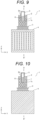
- FIG. 9 is a cross-sectional view schematically illustrating the temperature control device 1 according to Embodiment 5 of the present invention, and is a cross-sectional view at the same position as that in FIG. 8 .
- the plurality of hollow parts 7 provided inside the temperature regulating block 2 communicate with each other by a connection part 7c.
- the connection part 7c is a cavity that connects the plurality of hollow parts 7 to each other.
- FIG. 9 illustrates, as an example, the temperature regulating block 2 provided with the recess 2d, which has been described in Embodiment 4 ( FIG. 8 ).
- FIG. 10 is a cross-sectional view of the temperature control device 1 taken along line D-D' in FIG. 9 .
- the line D-D' is a line parallel to the Z-direction.
- FIG. 10 is a cross-sectional view taken along the YZ plane.
- the hollow parts 7 communicate with each other by connection parts 7c in the X-direction, the Y-direction, and the Z-direction.
- the hollow parts 7 communicating with each other by the connection parts 7c are easily formed.
- a fluid for example, air, inert gas, or liquid
- the inside of the hollow part 7 is filled with a fluid, it is possible to uniformly fill the hollow part 7 connected by the connection part 7c.
- the size (cross-sectional area) of the connection part 7c is smaller than the size (cross-sectional area) of the hollow part 7.
- connection part 7c In the temperature regulating block 2, all the hollow parts 7 may not communicate with each other by the connection part 7c, and only specific parts among the hollow parts 7 may communicate with each other by the connection part 7c.
- the size (cross-sectional area) of the connection part 7c can be freely determined, and may be equal to or different from the size (cross-sectional area) of the hollow part 7. For example, a configuration in which the size of the connection part 7c is set to be equal to the size of the hollow part 7, and the hollow part 7 is set to communicate with the temperature regulating block 2 without changing the size of the hollow part 7 may be made.
- a temperature control device 1 according to Embodiment 6 of the present invention will be described.
- the plurality of hollow parts 7 provided inside the temperature regulating block 2 communicate with each other and communicate with the outside of the temperature regulating block 2.
- FIG. 11 is a cross-sectional view schematically illustrating the temperature control device 1 according to Embodiment 6 of the present invention, and is a cross-sectional view at the same position as that in FIG. 9 .
- the temperature regulating block 2 is provided with an opening 7d on the surface.
- FIG. 11 illustrates, as an example, the temperature regulating block 2 provided with a recess 2d, which has been described in Embodiment 4 ( FIG. 8 ) .
- the plurality of hollow parts 7 provided inside the temperature regulating block 2 communicate with each other by the connection part 7c, and communicate with the outside of the temperature regulating block 2 from the opening 7d.
- the opening 7d can be provided at any position on the surface of the temperature regulating block 2.
- the hollow part 7 communicates with the outside of the temperature regulating block 2, it is possible to easily form the hollow part 7 as described in Embodiment 1. Furthermore, it is possible to easily fill the hollow part 7 with a fluid (for example, inert gas or liquid), dispose a heat insulating material, and perform an operation of vacuuming the inside of the hollow part 7.
- a fluid for example, inert gas or liquid
- thermocontrol device 1 according to Embodiment 7 of the present invention will be described.
- the temperature regulating block 2 is provided with, on an inside thereof, a plurality of regions having different arrangement densities of the hollow parts 7.
- FIG. 12 is a cross-sectional view schematically illustrating the temperature control device 1 according to Embodiment 7 of the present invention, and is a cross-sectional view at the same position as that in FIG. 8 .
- the temperature regulating block 2 is provided with, on the inside thereof, two regions having different arrangement densities of the hollow parts 7. That is, the temperature regulating block 2 is provided with, on the inside thereof, a region 7e having a high arrangement density of the hollow parts 7 and a region 7f having a low arrangement density of the hollow parts 7.
- FIG. 12 illustrates, as an example, the temperature regulating block 2 provided with a recess 2d, which has been described in Embodiment 4 ( FIG. 8 ).
- the arrangement density of the hollow parts 7 varies depending on the distance from the recess 2d, that is, the distance from the reaction container 5 accommodating the reaction solution 6.
- the arrangement density of the hollow parts 7 varies in the horizontal plane direction (in the XY plane) of the temperature regulating block 2.
- the region 7f having a low arrangement density of the hollow parts 7 is located at a position close to the recess 2d (or the reaction container 5) in the temperature regulating block 2, that is, a position adjacent to the recess 2d (or the reaction container 5).
- the region 7e having a high arrangement density of the hollow parts 7 is high is located at a position far from the recess 2d (or the reaction container 5) in the temperature regulating block 2, that is, a position adjacent to the region 7f having a low arrangement density of the hollow parts 7. Therefore, the region 7f having a low arrangement density of the hollow part 7 is located closer to the recess 2d (or the reaction container 5) than the region 7e having a high arrangement density of the hollow part 7. In the example illustrated in FIG. 12 , the region 7f having a low arrangement density of the hollow parts 7 is located at the central portion of the temperature regulating block 2, and the region 7e having a high arrangement density of the hollow parts 7 is located at the peripheral portion of the temperature regulating block 2.
- the thermal conductivity of the temperature regulating block 2 is large at the position close to the reaction container 5.
- the region 7e having a high arrangement density of the hollow part 7 is located far from the reaction container 5, at a position far from the reaction container 5, the density of the temperature regulating block 2 decreases, the heat capacity decreases, and the temperature change increases.
- the region 7e having a high arrangement density of the hollow parts 7 is located at the peripheral portion of the temperature regulating block 2, and to reduce the thermal conductivity of the temperature regulating block 2 at this position. Therefore, in the temperature regulating block 2, since the thermal resistance from the region 7f having a low arrangement density of the hollow parts 7 to the region 7e having a high arrangement density of the hollow parts 7 increases, it is possible to suppress heat dissipation from the surface to the outside air, and the temperature change becomes faster.
- thermocontrol device 1 according to Embodiment 8 of the present invention will be described.
- the temperature regulating block 2 is provided with, on an inside thereof, a plurality of regions having different arrangement densities of the hollow parts 7.
- FIG. 13 is a cross-sectional view schematically illustrating the temperature control device 1 according to Embodiment 8 of the present invention, and is a cross-sectional view at the same position as that in FIG. 8 .
- the temperature regulating block 2 is provided with, on the inside thereof, two regions having different arrangement densities of the hollow parts 7. That is, the temperature regulating block 2 is provided with, on the inside thereof, a region 7g having a low arrangement density of the hollow parts 7 and a region 7h having a high arrangement density of the hollow parts 7.
- FIG. 12 illustrates, as an example, the temperature regulating block 2 provided with a recess 2d, which has been described in Embodiment 4 ( FIG. 8 ).
- the arrangement density of the hollow parts 7 is different between portions above and below the position of the liquid level of the reaction solution 6 accommodated in the reaction container 5 placed in the recess 2d.
- the region 7g having a low arrangement density of the hollow parts 7 is located below the position of the liquid level of the reaction solution 6 accommodated in the reaction container 5 in the temperature regulating block 2.
- the region 7h having a high arrangement density of the hollow parts 7 is located above the position of the liquid level of the reaction solution 6 in the temperature regulating block 2. Therefore, in the example illustrated in FIG. 13 , the region 7g having a low arrangement density of the hollow parts 7 is located at the lower portion of the temperature regulating block 2, and the region 7h having a high arrangement density of the hollow parts 7 is located at the upper portion of the temperature regulating block 2.
- the position of the liquid level of the reaction solution 6 accommodated in the reaction container 5 varies depending on the reaction container 5 and the reaction solution 6, but an approximate position can be determined in advance. Therefore, the position of a boundary in the vertical direction (Z-direction) between the region 7g having a low arrangement density of the hollow parts and the region 7h having a high arrangement density of the hollow parts can be determined in advance as the approximate position of the liquid level of the reaction solution 6 based on information on the reaction container 5 and the reaction solution 6.
- the region 7h having a high arrangement density of the hollow parts 7 is a region in which the ratio of the volume of the hollow part 7 in the temperature regulating block 2 is large, the thermal conductivity of the temperature regulating block 2 decreases, and the temperature change of the temperature regulating block 2 is slow.
- the region 7h having a high arrangement density of the hollow parts 7 is a region in which the ratio of the volume of the hollow part 7 in the temperature regulating block 2 exceeds 85% and the thermal conductivity of the temperature regulating block 2 decreases as illustrated in FIG. 4 .
- the temperature regulating block 2 has the region 7g having a low arrangement density of the hollow parts 7 below the position of the liquid level of the reaction solution 6, and the thermal conductivity is large and the temperature change is fast. Thus, it is possible to transfer the heat of the temperature regulating part 3 quickly to the reaction solution 6.
- the temperature regulating block 2 has the region 7h having a high arrangement density of the hollow parts 7 above the position of the liquid level of the reaction solution 6, and the thermal conductivity is small and the temperature change is slow. Thus, it is possible to suppress the heat dissipation from the upper surface 2c of the temperature regulating block 2 and to further accelerate the temperature change of the entire temperature regulating block 2.
- the temperature regulating block 2 is provided with one or a plurality of hollow parts 7 on the inside thereof.
- the hollow part 7 has a tubular shape extending in the Z-direction (vertical direction), and can have any shape such as a rectangular cylindrical shape or a cylindrical shape.
- FIG. 14 is a cross-sectional view schematically illustrating the temperature control device 1 according to Embodiment 9 of the present invention, and is a cross-sectional view at the same position as that in FIG. 8 .
- FIG. 14 illustrates, as an example, the temperature regulating block 2 provided with one cylindrical hollow part 7 on the inside thereof.
- the cylindrical hollow part 7 is provided at the peripheral portion (outer peripheral portion) of the temperature regulating block 2.
- FIG. 14 illustrates, as an example, the temperature regulating block 2 provided with the recess 2d, which has been described in Embodiment 4 ( FIG. 8 ).
- FIG. 15 is a cross-sectional view of the temperature control device 1 on the horizontal plane (XY plane) passing through a line F-F' in FIG. 14 .
- the hollow part 7 has a rectangular tube shape and is provided at a peripheral portion of the temperature regulating block 2.
- the cylindrical hollow part 7 surrounds the periphery of the recess 2d and surrounds the periphery of the reaction container 5 placed in the recess 2d.
- the temperature regulating block 2 since the temperature regulating block 2 is provided with the cylindrical hollow part 7 surrounding the periphery of the recess 2d (or the reaction container 5), the thermal conductivity from the recess 2d to the outside of the temperature regulating block 2 decreases, the thermal resistance increases, and it is possible to suppress the heat dissipation from the surface to the outside air. Therefore, the temperature regulating block 2 can suppress the amount of heat dissipation from the side surface, and can further accelerate the temperature change of the entire temperature regulating block 2.
- thermocontrol device 1 according to Embodiment 10 of the present invention will be described.
- the temperature regulating block 2 is provided with a plurality of hollow parts 7 at a lower portion in contact with the temperature regulating part 3.
- FIG. 16 is a cross-sectional view schematically illustrating the temperature control device 1 according to Embodiment 10 of the present invention, and is a cross-sectional view at the same position as that in FIG. 8 .
- FIG. 16 illustrates, as an example, the temperature regulating block 2 also including the cylindrical hollow part 7 surrounding the periphery of the recess 2d (or the reaction container 5) described in Embodiment 9 ( FIG. 14 ).
- the temperature regulating block 2 is provided with the recess 2d described in Embodiment 4 ( FIG. 8 ) .
- the reaction container 5 accommodating the reaction solution 6 is placed in the recess 2d.
- the temperature regulating block 2 is provided with a plurality of hollow parts 7 (7n) at the lower portion in contact with the temperature regulating part 3, more specifically, between the bottom surface 2e in contact with the temperature regulating part 3 and the lower portion of the recess 2d.
- the temperature regulating block 2 is provided with a heat conduction path 8 from the temperature regulating part 3 to the recess 2d (that is, the reaction container 5) between the plurality of hollow parts 7n.
- the plurality of hollow parts 7n are located between the temperature regulating part 3 and the recess 2d in the temperature regulating block 2 and extend upward from a portion of the temperature regulating block 2 in contact with the temperature regulating part 3 toward the recess 2d.
- a space between the hollow parts 7n extends to connect the temperature regulating part 3 and the recess 2d to form the heat conduction path 8 from the temperature regulating part 3 to the recess 2d.
- the heat conduction path 8 extends upward from the bottom surface 2e of the temperature regulating block 2 in contact with the temperature regulating part 3, reaches the lower portion of the recess 2d of the temperature regulating block 2, and conducts heat of the temperature regulating part 3 to the lower portion of the recess 2d (that is, the lower portion of the reaction container 5) .
- the temperature regulating block 2 is preferably provided with a plurality of heat conduction paths 8.
- the temperature regulating block 2 may or may not be provided with the cylindrical hollow part 7 surrounding the periphery of the recess 2d (or the reaction container 5) .
- the temperature regulating block 2 is provided with the plurality of hollow parts 7n at the lower portion in contact with the temperature regulating part 3, and is provided with the heat conduction path 8 extending upward from the bottom surface 2e.
- the temperature regulating block 2 can efficiently transfer the heat generated in the temperature regulating part 3 to the reaction container 5, and can make the temperature change of the reaction container 5 faster.
- the present invention is not limited to the above embodiments, and various modifications are possible.
- the above-described embodiments have been described in detail in order to describe the present invention in an easy-to-understand manner, and the present invention is not necessarily limited to an aspect including all the described configurations.
- a part of the configuration of one embodiment can be replaced with the configuration of another embodiment.
- the configuration of another embodiment can be added to the configuration of one embodiment.
- a part of the configuration of each embodiment can be deleted, or another configuration can be added or replaced.
Landscapes
- Chemical & Material Sciences (AREA)
- Life Sciences & Earth Sciences (AREA)
- Health & Medical Sciences (AREA)
- Organic Chemistry (AREA)
- Engineering & Computer Science (AREA)
- Zoology (AREA)
- Wood Science & Technology (AREA)
- Bioinformatics & Cheminformatics (AREA)
- Biochemistry (AREA)
- General Health & Medical Sciences (AREA)
- Biotechnology (AREA)
- Chemical Kinetics & Catalysis (AREA)
- General Engineering & Computer Science (AREA)
- Genetics & Genomics (AREA)
- Microbiology (AREA)
- Physics & Mathematics (AREA)
- Proteomics, Peptides & Aminoacids (AREA)
- Analytical Chemistry (AREA)
- Molecular Biology (AREA)
- Sustainable Development (AREA)
- Biomedical Technology (AREA)
- Biophysics (AREA)
- Thermal Sciences (AREA)
- Immunology (AREA)
- Clinical Laboratory Science (AREA)
- Medicinal Chemistry (AREA)
- Control Of Temperature (AREA)
- Apparatus Associated With Microorganisms And Enzymes (AREA)
- Measuring Or Testing Involving Enzymes Or Micro-Organisms (AREA)
- Physical Or Chemical Processes And Apparatus (AREA)
Applications Claiming Priority (1)
| Application Number | Priority Date | Filing Date | Title |
|---|---|---|---|
| PCT/JP2020/033303 WO2022049678A1 (ja) | 2020-09-02 | 2020-09-02 | 温度制御装置 |
Publications (2)
| Publication Number | Publication Date |
|---|---|
| EP4209574A1 true EP4209574A1 (de) | 2023-07-12 |
| EP4209574A4 EP4209574A4 (de) | 2024-04-17 |
Family
ID=80491856
Family Applications (1)
| Application Number | Title | Priority Date | Filing Date |
|---|---|---|---|
| EP20952418.0A Pending EP4209574A4 (de) | 2020-09-02 | 2020-09-02 | Temperaturregelvorrichtung |
Country Status (7)
| Country | Link |
|---|---|
| US (1) | US20230294101A1 (de) |
| EP (1) | EP4209574A4 (de) |
| JP (1) | JP7488904B2 (de) |
| KR (1) | KR20230028493A (de) |
| CN (1) | CN115997031A (de) |
| TW (1) | TWI801966B (de) |
| WO (1) | WO2022049678A1 (de) |
Family Cites Families (14)
| Publication number | Priority date | Publication date | Assignee | Title |
|---|---|---|---|---|
| US6703236B2 (en) * | 1990-11-29 | 2004-03-09 | Applera Corporation | Thermal cycler for automatic performance of the polymerase chain reaction with close temperature control |
| KR100236506B1 (ko) * | 1990-11-29 | 2000-01-15 | 퍼킨-엘머시터스인스트루먼츠 | 폴리머라제 연쇄 반응 수행 장치 |
| DE29623597U1 (de) * | 1996-11-08 | 1999-01-07 | Eppendorf - Netheler - Hinz Gmbh, 22339 Hamburg | Temperierblock mit Temperiereinrichtungen |
| US8676383B2 (en) * | 2002-12-23 | 2014-03-18 | Applied Biosystems, Llc | Device for carrying out chemical or biological reactions |
| US7632464B2 (en) * | 2006-06-29 | 2009-12-15 | Bio-Rad Laboratories, Inc. | Low-mass sample block with rapid response to temperature change |
| JP5251882B2 (ja) * | 2007-10-26 | 2013-07-31 | 凸版印刷株式会社 | 反応チップ及び反応方法、遺伝子処理装置用温度調節機構及び遺伝子処理装置 |
| CN102164674B (zh) | 2008-09-23 | 2014-07-16 | 皇家飞利浦电子股份有限公司 | 热循环设备 |
| CN102917796B (zh) * | 2010-04-20 | 2015-04-01 | 科贝特研究私人有限公司 | 温度控制方法和设备 |
| US9149809B2 (en) * | 2011-05-06 | 2015-10-06 | Bio-Rad Laboratories, Inc. | Thermal cycler with vapor chamber for rapid temperature changes |
| JP6803030B2 (ja) * | 2015-12-01 | 2020-12-23 | 日本板硝子株式会社 | Pcr方法 |
| US11602752B2 (en) * | 2016-06-30 | 2023-03-14 | Seegene, Inc. | Apparatus for amplificating nucleic acid and fluorescence-detecting device |
| US11173491B2 (en) * | 2017-01-25 | 2021-11-16 | U-gene & Cell Co. | Apparatus for high-speed nucleic acid amplification and method for temperature control of nucleic acid amplification reaction |
| JP7060997B2 (ja) * | 2018-04-02 | 2022-04-27 | 株式会社日立ハイテク | 温度制御装置、及び遺伝子検査装置 |
| CN108998371A (zh) * | 2018-09-28 | 2018-12-14 | 北京金豪制药股份有限公司 | 一种低压磁感应加热的pcr控温装置 |
-
2020
- 2020-09-02 EP EP20952418.0A patent/EP4209574A4/de active Pending
- 2020-09-02 WO PCT/JP2020/033303 patent/WO2022049678A1/ja not_active Ceased
- 2020-09-02 US US18/018,622 patent/US20230294101A1/en active Pending
- 2020-09-02 JP JP2022546783A patent/JP7488904B2/ja active Active
- 2020-09-02 CN CN202080104070.5A patent/CN115997031A/zh active Pending
- 2020-09-02 KR KR1020237002747A patent/KR20230028493A/ko not_active Ceased
-
2021
- 2021-08-16 TW TW110130109A patent/TWI801966B/zh active
Also Published As
| Publication number | Publication date |
|---|---|
| JPWO2022049678A1 (de) | 2022-03-10 |
| KR20230028493A (ko) | 2023-02-28 |
| TW202210983A (zh) | 2022-03-16 |
| WO2022049678A1 (ja) | 2022-03-10 |
| US20230294101A1 (en) | 2023-09-21 |
| TWI801966B (zh) | 2023-05-11 |
| JP7488904B2 (ja) | 2024-05-22 |
| CN115997031A (zh) | 2023-04-21 |
| EP4209574A4 (de) | 2024-04-17 |
Similar Documents
| Publication | Publication Date | Title |
|---|---|---|
| EP2076605B2 (de) | Kühlung in einem thermocycler mit heizrohren | |
| KR100938374B1 (ko) | 다수의 샘플을 포함하는 블럭의 열순환 장치, 시스템 및 방법 | |
| US20120240597A1 (en) | Temperature control apparatus for samples storage | |
| CN112770841B (zh) | 变温反应器及其加热器和控制电路 | |
| CN101107507B (zh) | 用于具有不同热容的少量流体样品的温度控制器 | |
| KR20080052220A (ko) | 일회용 폴리머 칩을 이용한 자연대류 pcr 장치 및 그방법 | |
| US20230294101A1 (en) | Temperature Control Device | |
| JP5935980B2 (ja) | 熱サイクル装置 | |
| US20150343448A1 (en) | Nucleic acid amplification reaction apparatus | |
| KR20230108303A (ko) | 서멀 사이클러 및 유전자 검사 장치 | |
| CN103374510A (zh) | 一种基于低熔点金属液滴的pcr反应装置及其实施方法 | |
| EP3135376A1 (de) | Nukleinsäureamplifizierungsreaktionsbehälter, nukleinsäureamplifizierungsreaktionsvorrichtung und reaktionsverfahren zur amplifizierung von nukleinsäure | |
| EP4725600A1 (de) | Nukleinsäureamplifikation in tröpfchen | |
| Jones et al. | A micro-PCR chamber suitable for integration into a monolithic silicon lab-on-a-chip platform | |
| JP5935981B2 (ja) | 熱サイクル装置 | |
| EP4624929A1 (de) | Temperaturregelvorrichtung | |
| US12478969B2 (en) | Device for heating sample | |
| KR20240055060A (ko) | 열블록 | |
| CN116463212A (zh) | 一种核酸扩增温度实时控制装置及控制方法 | |
| JP2014135942A (ja) | 熱サイクル装置及び熱サイクル方法 | |
| US20150336101A1 (en) | Control method for nucleic acid amplification reaction apparatus | |
| JP2013044661A (ja) | 熱サイクル装置及び異常判定方法 |
Legal Events
| Date | Code | Title | Description |
|---|---|---|---|
| STAA | Information on the status of an ep patent application or granted ep patent |
Free format text: STATUS: THE INTERNATIONAL PUBLICATION HAS BEEN MADE |
|
| PUAI | Public reference made under article 153(3) epc to a published international application that has entered the european phase |
Free format text: ORIGINAL CODE: 0009012 |
|
| STAA | Information on the status of an ep patent application or granted ep patent |
Free format text: STATUS: REQUEST FOR EXAMINATION WAS MADE |
|
| 17P | Request for examination filed |
Effective date: 20230127 |
|
| AK | Designated contracting states |
Kind code of ref document: A1 Designated state(s): AL AT BE BG CH CY CZ DE DK EE ES FI FR GB GR HR HU IE IS IT LI LT LU LV MC MK MT NL NO PL PT RO RS SE SI SK SM TR |
|
| DAV | Request for validation of the european patent (deleted) | ||
| DAX | Request for extension of the european patent (deleted) | ||
| RIC1 | Information provided on ipc code assigned before grant |
Ipc: B01L 7/00 20060101ALI20231214BHEP Ipc: C12Q 1/686 20180101ALI20231214BHEP Ipc: C12M 1/00 20060101AFI20231214BHEP |
|
| A4 | Supplementary search report drawn up and despatched |
Effective date: 20240314 |
|
| RIC1 | Information provided on ipc code assigned before grant |
Ipc: B01L 7/00 20060101ALI20240308BHEP Ipc: C12Q 1/686 20180101ALI20240308BHEP Ipc: C12M 1/00 20060101AFI20240308BHEP |