EP4209631A1 - Beweglicher konsolenmechanismus für mensch-maschine-schnittstelle - Google Patents
Beweglicher konsolenmechanismus für mensch-maschine-schnittstelle Download PDFInfo
- Publication number
- EP4209631A1 EP4209631A1 EP22203925.7A EP22203925A EP4209631A1 EP 4209631 A1 EP4209631 A1 EP 4209631A1 EP 22203925 A EP22203925 A EP 22203925A EP 4209631 A1 EP4209631 A1 EP 4209631A1
- Authority
- EP
- European Patent Office
- Prior art keywords
- user interface
- bezel
- cabinet
- household appliance
- respect
- Prior art date
- Legal status (The legal status is an assumption and is not a legal conclusion. Google has not performed a legal analysis and makes no representation as to the accuracy of the status listed.)
- Withdrawn
Links
- 238000012986 modification Methods 0.000 description 1
- 230000004048 modification Effects 0.000 description 1
Images




Classifications
-
- D—TEXTILES; PAPER
- D06—TREATMENT OF TEXTILES OR THE LIKE; LAUNDERING; FLEXIBLE MATERIALS NOT OTHERWISE PROVIDED FOR
- D06F—LAUNDERING, DRYING, IRONING, PRESSING OR FOLDING TEXTILE ARTICLES
- D06F34/00—Details of control systems for washing machines, washer-dryers or laundry dryers
- D06F34/28—Arrangements for program selection, e.g. control panels therefor; Arrangements for indicating program parameters, e.g. the selected program or its progress
- D06F34/30—Arrangements for program selection, e.g. control panels therefor; Arrangements for indicating program parameters, e.g. the selected program or its progress characterised by mechanical features, e.g. buttons or rotary dials
-
- D—TEXTILES; PAPER
- D06—TREATMENT OF TEXTILES OR THE LIKE; LAUNDERING; FLEXIBLE MATERIALS NOT OTHERWISE PROVIDED FOR
- D06F—LAUNDERING, DRYING, IRONING, PRESSING OR FOLDING TEXTILE ARTICLES
- D06F34/00—Details of control systems for washing machines, washer-dryers or laundry dryers
- D06F34/28—Arrangements for program selection, e.g. control panels therefor; Arrangements for indicating program parameters, e.g. the selected program or its progress
- D06F34/32—Arrangements for program selection, e.g. control panels therefor; Arrangements for indicating program parameters, e.g. the selected program or its progress characterised by graphical features, e.g. touchscreens
-
- H—ELECTRICITY
- H05—ELECTRIC TECHNIQUES NOT OTHERWISE PROVIDED FOR
- H05K—PRINTED CIRCUITS; CASINGS OR CONSTRUCTIONAL DETAILS OF ELECTRIC APPARATUS; MANUFACTURE OF ASSEMBLAGES OF ELECTRICAL COMPONENTS
- H05K5/00—Casings, cabinets or drawers for electric apparatus
- H05K5/0017—Casings, cabinets or drawers for electric apparatus with operator interface units
-
- H—ELECTRICITY
- H05—ELECTRIC TECHNIQUES NOT OTHERWISE PROVIDED FOR
- H05K—PRINTED CIRCUITS; CASINGS OR CONSTRUCTIONAL DETAILS OF ELECTRIC APPARATUS; MANUFACTURE OF ASSEMBLAGES OF ELECTRICAL COMPONENTS
- H05K5/00—Casings, cabinets or drawers for electric apparatus
- H05K5/0017—Casings, cabinets or drawers for electric apparatus with operator interface units
- H05K5/0018—Casings, cabinets or drawers for electric apparatus with operator interface units having an electronic display
-
- D—TEXTILES; PAPER
- D06—TREATMENT OF TEXTILES OR THE LIKE; LAUNDERING; FLEXIBLE MATERIALS NOT OTHERWISE PROVIDED FOR
- D06F—LAUNDERING, DRYING, IRONING, PRESSING OR FOLDING TEXTILE ARTICLES
- D06F25/00—Washing machines with receptacles, e.g. perforated, having a rotary movement, e.g. oscillatory movement, the receptacle serving both for washing and for centrifugally separating water from the laundry and having further drying means, e.g. using hot air
-
- D—TEXTILES; PAPER
- D06—TREATMENT OF TEXTILES OR THE LIKE; LAUNDERING; FLEXIBLE MATERIALS NOT OTHERWISE PROVIDED FOR
- D06F—LAUNDERING, DRYING, IRONING, PRESSING OR FOLDING TEXTILE ARTICLES
- D06F34/00—Details of control systems for washing machines, washer-dryers or laundry dryers
- D06F34/28—Arrangements for program selection, e.g. control panels therefor; Arrangements for indicating program parameters, e.g. the selected program or its progress
- D06F34/34—Arrangements for program selection, e.g. control panels therefor; Arrangements for indicating program parameters, e.g. the selected program or its progress characterised by mounting or attachment features, e.g. detachable control panels or detachable display panels
Definitions
- the present disclosure relates to household appliances and, more particularly, to washers, dryers, and combination washer/dryer machines with a movable human machine interface.
- Household appliances such as washers, dryers, and combination washer/dryers, typically include a cabinet that receives operable elements as well as a console.
- the console includes various types of controls for operation of the particular appliance.
- the consoles include an interface that provides the user with information about the functioning of the appliance.
- these interfaces are fixed to the console.
- the interface may be fixed at an angle with respect to the front surface of the console and therefore may be at an angle with respect to the front face of the appliance, which is typically perpendicular to the ground or slightly angled with respect to the ground. This fixing or positioning of the interface is designed and selected for viewing by a specific group of users. Thus, it does not provide optimal viewing for all percentages of users.
- a tall user is required to bend or kneel down in order to see the particular interface.
- Handicap people in wheelchairs may not be able to view the particular interface.
- a substantial percentage of users may be unable to readily view the interface associated with the appliance console.
- the present disclosure provides a human machine interface that is viewable by substantially all perspective users.
- the present disclosure provides an interface that is movable between positions to enable users of all heights to readily view and ascertain the information on the interface.
- a household appliance comprises a cabinet with operable elements of the appliance within the cabinet.
- a control console is associated with and generally positioned on a front panel or on a top of the appliance.
- a human machine interface for supplying information to the user is associated with the control console.
- the interface moves with respect to the control console to provide a desired viewing zone for a user.
- the interface further comprises a bezel for holding the interface.
- the bezel is rotatable with respect to the console.
- a rotary damper is coupled with bezel to control rotation of the bezel and hold the bezel in one or more viewing zones.
- the bezel includes a pivot hinge defining an axis. The hinge is coupled with the rotary damper to enable rotation.
- the bezel is pushed to rotate away from or into the console to a position providing one of the desired viewing zones.
- An additional push on the bezel retracts the bezel to its original position with respect to the console.
- a ribbon cable is coupled between the interface and the controls of the appliance.
- the interface is angled with respect to a surface of the console at an angle of from about 0° to 45°. Also, the interface is positioned at an angle of about 0° to 30° with respect to an axis or plane of the viewer, which is substantially horizontal.
- the viewing zones compensate for various heights of the users.
- a human machine interface for a household appliance comprises an interface supplying information to a user.
- the interface may be coupled with a control console.
- the interface moves with respect to the control console to provide a desired viewing zone for the user.
- the interface further comprises a bezel for holding the interface.
- the bezel is rotatable with respect to the console.
- a rotary damper is coupled with the bezel to control rotation of the bezel and hold the bezel in one or more viewing zones.
- the bezel includes a pivot hinge defining an axis. The hinge is coupled with the rotary damper to enable the rotation. The bezel is pushed to rotate away from or into the console to a position providing one of the desired viewing zones.
- An additional push on the bezel retracts the bezel to its original position with respect to the console.
- a ribbon cable is coupled between the interface and the controls of the appliance.
- the interface is angled with respect to a surface of the console at an angle of from about 0° to 45°. Also, the interface is positioned at an angle of about 0° to 30° with respect to an axis or plane of the viewer, which is substantially horizontal. The viewing zones compensate for various heights of the users.
- a console for a household appliance comprises a housing defining a console.
- the housing includes a front face.
- An interface supplying information to a user may be coupled with a control console.
- the interface moves with respect to the control console to provide a desired viewing zone for the user.
- the interface further comprises a bezel for holding the interface.
- the bezel is rotatable with respect to the console.
- a rotary damper is coupled with the bezel to control rotation of the bezel and hold the bezel in one or more viewing zones.
- the bezel includes a pivot hinge defining an axis. The hinge is coupled with the rotary damper to enable the rotation. The bezel is pushed to rotate away from or into the console to a position providing one of the desired viewing zones.
- An additional push on the bezel retracts the bezel to its original position with respect to the console.
- a ribbon cable is coupled between the interface and the controls of the appliance.
- the interface is angled with respect to a surface of the console at an angle of from about 0° to 45°. Also, the interface is positioned at an angle of about 0° to 30° with respect to an axis or plane of the viewer, which is substantially horizontal. The viewing zones compensate for various heights of the users.
- a household appliance comprising a cabinet and a user interface for supplying information to a user.
- the user interface is movable with respect to the cabinet with a bezel holding the user interface.
- the bezel is rotatable with respect to the cabinet and at least one rotary damper or linkage, coupled with the bezel, controls rotation of the bezel and holds the bezel and user interface in multiple viewing positions.
- the bezel includes hinge pins that couple the bezel with two rotary dampers.
- the user interface has a screen and the bezel may include two lateral legs and two longitudinal legs.
- One of the longitudinal legs of the bezel may include an opening to enable the screen to slide into the bezel.
- the bezel may have two lateral legs and one longitudinal leg to give the bezel a U-shape.
- the bezel may have a channel that is configured to receive the screen.
- the user interface pops out of the cabinet via an L-shaped linkage to provide a raised user interface.
- the user interface rotates via the linkage to a position where the user interface is in front of and substantially parallel to a front face of the cabinet.
- the linkage slides along in a channel that enables the linkage to be raised and rotated which raises and rotates the user interface to the multiple viewing positions.
- the cabinet includes a top face and the user interface is flush-mounted with the top face of the cabinet in at least one of the multiple viewing positions.
- the user interface is moveable with respect to the top face of the cabinet within a range of angles between 0 degrees and 100 degrees.
- the cabinet includes a front face and the user interface is flush-mounted with the front face of the cabinet in at least one of the multiple viewing positions.
- the user interface is moveable with respect to the front face of the cabinet within a range of angles between negative 10 degrees and positive 90 degrees.
- the cabinet includes a control console on top of the cabinet and the user interface is flush-mounted with an outer face of the control console in at least one of the multiple viewing positions.
- the user interface is moveable with respect to the outer face of the control console within a range of angles between 0 degrees and 45 degrees.
- the rotatory dampers may be positioned in the control console.
- the household appliance 10 includes a cabinet 12 with a control console 14.
- the cabinet 12 includes a door 16 enabling access inside the cabinet 12 to the working operable elements of the household appliance 10.
- the control console 14 is illustrated as being on top of the cabinet 12. However, the control console 14 could be on a front face 17 or top face 19 of the cabinet 12.
- the control console 14 may include one or more user interfaces 20.
- the user interfaces 20 are human machine interfaces and provide a user with information on the household appliance 10. For example, the user interface 20 may provide information relating to functioning, using or operation of the household appliance 10.
- the user interface 20 is movable from a first position, substantially flush with the outer face 18 of the control console 14, to at least one second position angled with respect to the control console 14 as shown in Fig. 2 .
- the angle with respect to the control console 14 from the outer face 18 may vary between 0 degrees and 45 degrees.
- the user interface 20 is positioned at an angle of about 0 degrees and 30 degrees with respect to an axis or plane of the viewer, that is substantially horizontal. This provides for various viewing zones to compensate for various heights of users.
- the user interface 20 includes a screen 22 and a bezel 24 for receiving the screen 22.
- the bezel 24 includes hinge pins 26 that couple the bezel 24 with at least one rotary damper 28.
- the bezel 24 generally has an overall rectangular design to receive the rectangular screen 22. However, any shape or design could be utilized for the disclosure.
- the bezel 24 includes lateral legs 30 as well as longitudinal legs 32.
- the upper longitudinal leg 32 that is positioned closest to the hinge pins 26 includes an opening 33 at the top to enable the screen 22 to slide into the bezel 24.
- the upper longitudinal leg 32 could be eliminated to provide a U-shape bezel 24 configured to receive the screen 22 within channel 34, which may be defined by the lateral legs 30 and the lower longitudinal leg 32.
- the rotary dampers 28 are positioned in the control console 14.
- the rotary dampers 28 control the movement or pivoting rotation of the user interface 20.
- the user interface 20 rotates relative to the control console 14 to a position providing one of the desired viewing zones.
- An additional push on the user interface 20 may retract the screen 22 and bezel 24 into the control console 14.
- this provides various viewing zones to compensate for different heights of users.
- the user interface 20, in its flush position with the control console 14, can easily be read by an individual that would be sitting in a wheelchair or the like.
- the user would not need to move in order to view the user interface 20.
- the rotary dampers 28 may enable the user interface 20 to move inward into the control console 14. This enables an angle pointing downward with respect to the outer face 18 of the console 14 so that, if the user interface 20 is part of a stacked combination appliance, a shorter user could readily ascertain the information on the user interface 20.
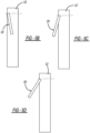
- Fig. 5A illustrates the user interface 20 positioned on the front face 17 of the cabinet 12.
- the user interface 20 is substantially flush with the front face 17 of the cabinet 12.
- the user interface 20 can be moved to a plurality of positions with respect to the cabinet 12 as illustrated in Figs. 5B-5D .
- the angle with respect to the front face 17 of the cabinet 12 may vary between -10 degrees to 90 degrees as the user interface 20 swings between positions.
- the user interface 20 is illustrated in a negative degree position that enables accessibility for a shorter person.
- Fig. 5C the user interface 20 is illustrated in a positive degree position that enables access for a medium to taller person.
- the user interface 20 is at a larger positive degree position that provides accessibility for a taller person.
- the user interface 20 can swing out of the cabinet 12 so that the user interface 20 is substantially parallel to the front face 17 of the cabinet 12.
- the user interface 20 is illustrated on the top face 19 of the cabinet 12.
- the user interface 20 is substantially flush with the top face 19 of the cabinet 12 and can be moved to a number of positions.
- the angle with respect to the top face 19 of the cabinet 12 may vary between 0 degrees to 100 degrees.
- Figs. 6B-6D the user interface 20 is illustrated at a small positive angle with respect to the top face 19 of the cabinet 12. Here, this allows accessibility for a taller person.
- the user interface 20 is approximately perpendicular with the top face 19 of the cabinet 12. Here, this allows accessibility for a medium to taller person.
- Fig. 6D illustrates the user interface 20 angled at approximately 100 degrees faced downward toward horizontal to provide accessibility for a shorter person.
- Figs. 7A-7D and Figs. 8A-8D illustrate an additional embodiment.
- the user interface 20 is positioned on the top face 19 of the cabinet 12 like that in Fig. 6A .
- the user interface 20 pops out of the cabinet 12, via a linkage 21, to provide a raised user interface 20 as illustrated in Fig. 7B .
- the user interface 20 is rotated via the linkage 21 to a position where it is in front of and substantially parallel to the front face 17 of the cabinet 12.
- this provides an angle with respect to the top face 19 of the cabinet 12 from between 0 degrees to 270 degrees with respect to the top face 19 of the cabinet 12.
- Figs. 7A-7D and Figs. 8A-8D illustrate an additional embodiment.
- the user interface 20 is positioned on the top face 19 of the cabinet 12 like that in Fig. 6A .
- the user interface 20 pops out of the cabinet 12, via a linkage 21, to provide a raised user interface 20 as illustrated in Fig. 7B .
- the linkage has an overall L-shape and slides along in a channel 23 that enables the linkage to be raised and rotated which, in turn, raises and rotates the user interface 20 to the positions illustrated in Figs. 7B-7D .
- the user interface 20 is capable for accommodating taller and shorter people to enable accessibility.
Landscapes
- Engineering & Computer Science (AREA)
- Textile Engineering (AREA)
- Microelectronics & Electronic Packaging (AREA)
- Casings For Electric Apparatus (AREA)
Applications Claiming Priority (1)
| Application Number | Priority Date | Filing Date | Title |
|---|---|---|---|
| US17/563,528 US20230203734A1 (en) | 2021-12-28 | 2021-12-28 | Console HMI Interface Mechanism |
Publications (1)
| Publication Number | Publication Date |
|---|---|
| EP4209631A1 true EP4209631A1 (de) | 2023-07-12 |
Family
ID=84034113
Family Applications (1)
| Application Number | Title | Priority Date | Filing Date |
|---|---|---|---|
| EP22203925.7A Withdrawn EP4209631A1 (de) | 2021-12-28 | 2022-10-26 | Beweglicher konsolenmechanismus für mensch-maschine-schnittstelle |
Country Status (2)
| Country | Link |
|---|---|
| US (1) | US20230203734A1 (de) |
| EP (1) | EP4209631A1 (de) |
Citations (5)
| Publication number | Priority date | Publication date | Assignee | Title |
|---|---|---|---|---|
| DE3621260A1 (de) * | 1986-06-25 | 1988-01-21 | Bosch Siemens Hausgeraete | Haushaltgeraet mit an einem schrankfoermigen gehaeuse angeordneter bedienungsblende |
| WO2006072903A2 (en) * | 2005-01-03 | 2006-07-13 | Arcelik Anonim Sirketi | A household appliance |
| US20070113594A1 (en) * | 2005-06-30 | 2007-05-24 | Lg Electronics Inc. | Laundry machine with screen displaying image data therein |
| EP2172142A1 (de) * | 2008-10-03 | 2010-04-07 | FagorBrandt SAS | Steuerverfahren zum Bewegen eines mobilen Organs einer Bedienblende eines Elektrohaushaltgeräts und entsprechendes Elektrohaushaltsgerät |
| CN112746447A (zh) * | 2020-12-24 | 2021-05-04 | 珠海格力电器股份有限公司 | 一种洗衣机控制面板结构及其控制方法和洗衣机 |
Family Cites Families (1)
| Publication number | Priority date | Publication date | Assignee | Title |
|---|---|---|---|---|
| CN201611988U (zh) * | 2010-01-20 | 2010-10-20 | 超卓工业股份有限公司 | 旋转阻尼装置 |
-
2021
- 2021-12-28 US US17/563,528 patent/US20230203734A1/en not_active Abandoned
-
2022
- 2022-10-26 EP EP22203925.7A patent/EP4209631A1/de not_active Withdrawn
Patent Citations (5)
| Publication number | Priority date | Publication date | Assignee | Title |
|---|---|---|---|---|
| DE3621260A1 (de) * | 1986-06-25 | 1988-01-21 | Bosch Siemens Hausgeraete | Haushaltgeraet mit an einem schrankfoermigen gehaeuse angeordneter bedienungsblende |
| WO2006072903A2 (en) * | 2005-01-03 | 2006-07-13 | Arcelik Anonim Sirketi | A household appliance |
| US20070113594A1 (en) * | 2005-06-30 | 2007-05-24 | Lg Electronics Inc. | Laundry machine with screen displaying image data therein |
| EP2172142A1 (de) * | 2008-10-03 | 2010-04-07 | FagorBrandt SAS | Steuerverfahren zum Bewegen eines mobilen Organs einer Bedienblende eines Elektrohaushaltgeräts und entsprechendes Elektrohaushaltsgerät |
| CN112746447A (zh) * | 2020-12-24 | 2021-05-04 | 珠海格力电器股份有限公司 | 一种洗衣机控制面板结构及其控制方法和洗衣机 |
Also Published As
| Publication number | Publication date |
|---|---|
| US20230203734A1 (en) | 2023-06-29 |
Similar Documents
| Publication | Publication Date | Title |
|---|---|---|
| US6732661B2 (en) | Moving table flap | |
| US4669694A (en) | Tilt adjusting mechanism | |
| US5754395A (en) | Ergonomic keyboard for a portable computer which is moveable between two positions | |
| JP5333054B2 (ja) | 電子機器 | |
| US6318824B1 (en) | Hinged tracking system | |
| US20050041379A1 (en) | Monitor apparatus | |
| US7187554B2 (en) | Movable console device | |
| US6195839B1 (en) | Hinged detent | |
| US9372512B2 (en) | Portable electronic device | |
| US20030103324A1 (en) | Position adjustable display screen for portable computer devices | |
| US20170090522A1 (en) | Portable electronic device | |
| US20120154999A1 (en) | Electronic apparatus | |
| WO1996003685A1 (en) | Portable computing device having an adjustable hinge | |
| US11726522B2 (en) | Sliding input device cover | |
| JP5986156B2 (ja) | ヒンジ機構及び電子機器 | |
| US5368377A (en) | Flip-top computer workstation | |
| US5546270A (en) | Apparatus for supporting a display device in a plurality of positions | |
| EP3909467A1 (de) | Kabelverwaltungssystem und arbeitsplatzsystem | |
| US5938163A (en) | Articulating touchscreen interface | |
| US20230203734A1 (en) | Console HMI Interface Mechanism | |
| TWI290278B (en) | Automatic anti-tip over mechanism for display | |
| KR20110006494U (ko) | 슬라이딩부을 구비한 복수의 모니터를 가지는 랩텁 컴퓨터 | |
| KR20090062214A (ko) | 듀얼 모니터 | |
| US6262881B1 (en) | Compact notebook computer with movable keyboard section | |
| CN112558689B (zh) | 滑动输入设备覆盖件 |
Legal Events
| Date | Code | Title | Description |
|---|---|---|---|
| PUAI | Public reference made under article 153(3) epc to a published international application that has entered the european phase |
Free format text: ORIGINAL CODE: 0009012 |
|
| STAA | Information on the status of an ep patent application or granted ep patent |
Free format text: STATUS: THE APPLICATION HAS BEEN PUBLISHED |
|
| AK | Designated contracting states |
Kind code of ref document: A1 Designated state(s): AL AT BE BG CH CY CZ DE DK EE ES FI FR GB GR HR HU IE IS IT LI LT LU LV MC ME MK MT NL NO PL PT RO RS SE SI SK SM TR |
|
| STAA | Information on the status of an ep patent application or granted ep patent |
Free format text: STATUS: THE APPLICATION IS DEEMED TO BE WITHDRAWN |
|
| 18D | Application deemed to be withdrawn |
Effective date: 20240113 |