EP4209679A1 - Pompe à fluide et roue à aubes associée - Google Patents
Pompe à fluide et roue à aubes associée Download PDFInfo
- Publication number
- EP4209679A1 EP4209679A1 EP23150523.1A EP23150523A EP4209679A1 EP 4209679 A1 EP4209679 A1 EP 4209679A1 EP 23150523 A EP23150523 A EP 23150523A EP 4209679 A1 EP4209679 A1 EP 4209679A1
- Authority
- EP
- European Patent Office
- Prior art keywords
- impeller
- hub
- blades
- draft angle
- leg
- Prior art date
- Legal status (The legal status is an assumption and is not a legal conclusion. Google has not performed a legal analysis and makes no representation as to the accuracy of the status listed.)
- Granted
Links
Images


Classifications
-
- F—MECHANICAL ENGINEERING; LIGHTING; HEATING; WEAPONS; BLASTING
- F04—POSITIVE - DISPLACEMENT MACHINES FOR LIQUIDS; PUMPS FOR LIQUIDS OR ELASTIC FLUIDS
- F04D—NON-POSITIVE-DISPLACEMENT PUMPS
- F04D5/00—Pumps with circumferential or transverse flow
- F04D5/002—Regenerative pumps
-
- F—MECHANICAL ENGINEERING; LIGHTING; HEATING; WEAPONS; BLASTING
- F04—POSITIVE - DISPLACEMENT MACHINES FOR LIQUIDS; PUMPS FOR LIQUIDS OR ELASTIC FLUIDS
- F04D—NON-POSITIVE-DISPLACEMENT PUMPS
- F04D25/00—Pumping installations or systems
- F04D25/02—Units comprising pumps and their driving means
- F04D25/06—Units comprising pumps and their driving means the pump being electrically driven
-
- F—MECHANICAL ENGINEERING; LIGHTING; HEATING; WEAPONS; BLASTING
- F04—POSITIVE - DISPLACEMENT MACHINES FOR LIQUIDS; PUMPS FOR LIQUIDS OR ELASTIC FLUIDS
- F04D—NON-POSITIVE-DISPLACEMENT PUMPS
- F04D29/00—Details, component parts, or accessories
- F04D29/18—Rotors
-
- F—MECHANICAL ENGINEERING; LIGHTING; HEATING; WEAPONS; BLASTING
- F04—POSITIVE - DISPLACEMENT MACHINES FOR LIQUIDS; PUMPS FOR LIQUIDS OR ELASTIC FLUIDS
- F04D—NON-POSITIVE-DISPLACEMENT PUMPS
- F04D29/00—Details, component parts, or accessories
- F04D29/18—Rotors
- F04D29/188—Rotors specially for regenerative pumps
-
- F—MECHANICAL ENGINEERING; LIGHTING; HEATING; WEAPONS; BLASTING
- F04—POSITIVE - DISPLACEMENT MACHINES FOR LIQUIDS; PUMPS FOR LIQUIDS OR ELASTIC FLUIDS
- F04D—NON-POSITIVE-DISPLACEMENT PUMPS
- F04D29/00—Details, component parts, or accessories
- F04D29/40—Casings; Connections of working fluid
- F04D29/406—Casings; Connections of working fluid especially adapted for liquid pumps
-
- F—MECHANICAL ENGINEERING; LIGHTING; HEATING; WEAPONS; BLASTING
- F04—POSITIVE - DISPLACEMENT MACHINES FOR LIQUIDS; PUMPS FOR LIQUIDS OR ELASTIC FLUIDS
- F04D—NON-POSITIVE-DISPLACEMENT PUMPS
- F04D13/00—Pumping installations or systems
- F04D13/02—Units comprising pumps and their driving means
- F04D13/06—Units comprising pumps and their driving means the pump being electrically driven
- F04D13/08—Units comprising pumps and their driving means the pump being electrically driven for submerged use
-
- F—MECHANICAL ENGINEERING; LIGHTING; HEATING; WEAPONS; BLASTING
- F04—POSITIVE - DISPLACEMENT MACHINES FOR LIQUIDS; PUMPS FOR LIQUIDS OR ELASTIC FLUIDS
- F04D—NON-POSITIVE-DISPLACEMENT PUMPS
- F04D5/00—Pumps with circumferential or transverse flow
- F04D5/001—Shear force pumps
Definitions
- the present disclosure relates to a fluid pump with an impeller having a plurality of blades; particularly to a such a fluid pump where a draft angle between adjacent pairs of the plurality of blades varies along the radial length of the plurality of blades.
- Fluid pumps for pumping fluids for example liquid fuel
- a fluid pump is shown in United States Patent No. 6,527,506 to Pickelman et al .
- an impeller is rotated, for example by an electric motor.
- the impeller is sandwiched between two plates which each have a respective flow channel formed in a face thereof such that each flow channel faces toward the impeller.
- the impeller includes a plurality of blades arranged in a polar array such that the blades are aligned with the flow channels of the two plates.
- Each blade may be a V-shape such that the concave side of the V-shape faces toward the direction of rotation of the impeller and the convex side of the V-shape faces away from the direction of rotation of the impeller.
- the impeller including the plurality of blades, may be made as a unitary piece of plastic in an injection molding process where a pair of opposing molds form upper and lower halves of each blade.
- a draft angle typically about 10°, is provided between each adjacent pair of blades. Furthermore, this draft angle is maintained along the radial length of each blade. This draft angle minimizes friction as the molds are extracted, thereby minimizing the likely hood of damage to the blades.
- this arrangement also causes the distance between adjacent blades to widen further from the center of the impeller, much like spokes on a bicycle wheel.
- fuel enters between adjacent blades on the inboard half of the blade radial length and centrifugal forces causes the fuel to exit the blade on the outboard half of the of the blade radial length. Since the distance between adjacent blades widens from inboard to outboard, the flow stream exiting the blade diverges which may be undesirable for momentum transfer of the fuel, thereby leading to decreased pumping efficiency.
- the impeller includes a hub configured to be rotationally coupled to a shaft of the fluid pump such that the shaft provides rotational motion in a rotational direction about an axis, the hub having an outer surface; an outer ring which is concentric with the hub, the outer ring having an inner surface; and a plurality of blades extending from a root at the outer surface of the hub to a tip at the inner surface of the outer ring, each one of the plurality of blades having a first leg and a second leg which meet at a vertex, thereby forming a V-shape such that a concave side of the V-shape faces toward the rotational direction and such that a convex side of the V-shape faces away from the rotational direction.
- the first leg at the concave side of each one of the plurality of blades, forms a draft angle with the first leg at the convex side of another one of the plurality of blades which is immediately adjacent thereto in the rotational direction.
- the draft angle at the inner surface of the outer ring is less than or equal to 10% of the draft angle at the outer surface of the hub.
- the present disclosure also provides a fluid pump which includes a housing; an electric motor within the housing, the electric motor having a shaft which rotates when electricity is applied to the electric motor; and an impeller located between an inlet plate having an inlet plate flow channel facing toward the impeller and an outlet plate having an outlet plate flow channel facing toward the impeller.
- the impeller includes a hub rotationally coupled to the shaft such that the shaft provides rotational motion in a rotational direction about an axis, the hub having an outer surface; an outer ring which is concentric with the hub, the outer ring having an inner surface; and a plurality of blades extending from a root at the outer surface of the hub to a tip at the inner surface of the outer ring, each one of the plurality of blades having a first leg and a second leg which meet at a vertex, thereby forming a V-shape such that a concave side of the V-shape faces toward the rotational direction and such that a convex side of the V-shape faces away from the rotational direction.
- the first leg at the concave side of each one of the plurality of blades, forms a draft angle with the first leg at the convex side of another one of the plurality of blades which is immediately adjacent thereto in the rotational direction.
- the draft angle at the inner surface of the outer ring is less than or equal to 10% of the draft angle at the outer surface of the hub.
- the fluid pump and impeller as described herein provides for increased pumping efficiency while maintaining manufacturability of the impeller.
- Fuel pump 10 may be, by way of non-limiting example only, submersed in a fuel tank (not shown) which pumps fuel to a fuel consuming device (also not shown) such as an internal combustion engine.
- the fuel pumped by fuel pump 10 may be any liquid fuel customarily used, for example only, gasoline, diesel fuel, alcohol, ethanol, and the like, and blends thereof.
- Fuel pump 10 generally includes a pump section 12 at one end, a motor section 14 adjacent to pump section 12, and an outlet section 16 adjacent to motor section 14 at the end of fuel pump 10 opposite pump section 12.
- a housing 18 of fuel pump 10 is tubular and retains pump section 12, motor section 14 and outlet section 16 together. Fuel enters fuel pump 10 at pump section 12, a portion of which is rotated by motor section 14 as will be described in more detail later, and is pumped past motor section 14 to outlet section 16 where the fuel exits fuel pump 10.
- Motor section 14 includes an electric motor 20 which is disposed within housing 18.
- Electric motor 20 includes a shaft 22 extending therefrom into pump section 12.
- Shaft 22 rotates in a rotational direction 23 about an axis 24 when an electric current is applied to electric motor 20.
- Electric motors and their operation are well known to those of ordinary skill in the art and will not be described in greater detail herein.
- Pump section 12 includes an inlet plate 26, a pumping element illustrated as impeller 28, and an outlet plate 30.
- Inlet plate 26 is disposed at the end of pump section 12 that is distal from motor section 14 while outlet plate 30 is disposed at the end of pump section 12 that is proximal to motor section 14. Both inlet plate 26 and outlet plate 30 are fixed relative to housing 18 to prevent relative movement between inlet plate 26 and outlet plate 30 with respect to housing 18.
- Outlet plate 30 defines a spacer ring 32 on the side of outlet plate 30 that faces toward inlet plate 26.
- Impeller 28 is disposed axially between inlet plate 26 and outlet plate 30 such that impeller 28 is radially surrounded by spacer ring 32.
- Impeller 28 is fixed to shaft 22 such that impeller 28 rotates with shaft 22 in a one-to-one relationship.
- Spacer ring 32 is dimensioned to be slightly thicker than the dimension of impeller 28 in the direction of axis 24, i.e. the dimension of spacer ring 32 in the direction of axis 24 is greater than the dimension of impeller 28 in the direction of axis 24.
- inlet plate 26, outlet plate 30, and spacer ring 32 are fixed within housing 18, for example by crimping the axial ends of housing 18. Axial forces created by the crimping process will be carried by spacer ring 32, thereby preventing impeller 28 from being clamped tightly between inlet plate 26 and outlet plate 30 which would prevent impeller 28 from rotating freely.
- Spacer ring 32 is also dimensioned to have an inside diameter that is larger than the outside diameter of impeller 28 to allow impeller 28 to rotate freely within spacer ring 32 and axially between inlet plate 26 and outlet plate 30. While spacer ring 32 is illustrated as being made as a single piece with outlet plate 30, it should be understood that spacer ring 32 may alternatively be made as a separate piece that is captured axially between outlet plate 30 and inlet plate 26.
- Inlet plate 26 is generally cylindrical in shape, and includes an inlet passage 34 that extends through inlet plate 26 in the same direction as axis 24.
- Inlet passage 34 is a passage which introduces fuel into fuel pump 10/housing 18.
- Inlet plate 26 also includes an inlet plate flow channel 36 formed in the face of inlet plate 26 that faces toward impeller 28.
- Inlet plate flow channel 36 is a segment of an annulus and is in fluid communication with inlet passage 34.
- Outlet plate 30 is generally cylindrical in shape and includes an outlet plate outlet passage 38 that extends through outlet plate 30 where it should be noted that outlet plate outlet passage 38 is an outlet for pump section 12. Outlet plate outlet passage 38 is in fluid communication with outlet section 16. Outlet plate 30 also includes an outlet plate flow channel 40 formed in the face of outlet plate 30 that faces toward impeller 28. Outlet plate flow channel 40 is a segment of an annulus and is in fluid communication with outlet plate outlet passage 38. Outlet plate 30 also includes an outlet plate aperture, hereinafter referred to as lower bearing 42, extending through outlet plate 30.
- Shaft 22 extends through lower bearing 42 in a close-fitting relationship such that shaft 22 is able to rotate freely within lower bearing 42 and such that radial movement of shaft 22 within lower bearing 42 is limited to the manufacturing tolerances of shaft 22 and lower bearing 42. In this way, lower bearing 42 radially supports a lower end of shaft 22 that is proximal to pump section 12.
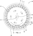
- impeller 28 includes a plurality of blades 44, as can be most clearly seen in FIG. 2 , arranged in a polar array radially surrounding, and centered about axis 24, such that blades 44 are aligned with inlet plate flow channel 36 and outlet plate flow channel 40. Blades 44 are each separated from each other by a respective blade chamber 46 that passes through impeller 28 in the general direction of axis 24. Impeller 28 may be made, for example only, by a plastic injection molding process in which the preceding features of impeller 28 are integrally molded as a single piece of plastic. Impeller 28 and blades 44 will be described in greater detail later.
- Outlet section 16 includes an end cap 48 which closes the upper end of housing 18.
- End cap 48 includes an outlet conduit 50 which provides fluid communication out of housing 18 such that outlet conduit 50 is in fluid communication with outlet plate outlet passage 38 of outlet plate 30 for receiving fuel that has been pumped by pump section 12.
- Rotation of impeller 28 by shaft 22 causes fluid to be pumped from inlet passage 34 to outlet conduit 50 and to be pressurized within housing 18 such that pressurized fuel is communicated out of housing 18.
- fuel pump 10 may also include a check valve assembly 52 which allows fuel to flow out of fuel pump 10 through outlet conduit 50 but prevents fuel from flowing into fuel pump 10 through outlet conduit 50.
- Impeller 28 will now be described in greater detail with particular reference to FIGS. 2-5B .
- Impeller 28 includes a hub 54 defining an aperture 56 extending axially therethrough at a center of hub 54.
- shaft 22 extends into aperture 56 and shaft 22 is rotationally coupled to hub 54 by way of complementary features which cause rotational motion of shaft 22 to be transferred to impeller 28 in rotational direction 23 about axis 24.
- Hub 54 includes an outer surface 58 which surrounds, and extends along, axis 24 and which may be cylindrical.
- Impeller 28 also includes an outer ring 60 which is concentric to hub 54.
- Outer ring 60 includes an inner surface 62 which surrounds, and extends along, axis 24 and which may be cylindrical.
- Each blade 44 extends radially outward from a respective root 44a at outer surface 58 to a tip 44b at inner surface 62.
- Each blade 44 includes a first leg 44c and a second leg 44d, which meet at a vertex 44e, thereby forming a V-shape such that a concave side 44f of the V-shape faces toward rotational direction 23 and such that a convex side 44g of the V-shape faces away from rotational direction 23.
- concave side 44f of first leg 44c forms a draft angle 64 n with convex side 44g of first leg 44c of the blade 44 which is immediately adjacent thereto in rotational direction 23 where n is used to represent different radial locations between outer surface 58 and inner surface 62 because draft angle 64 n varies between outer surface 58 and inner surface 62 and therefore is not uniform.
- draft angle 64 n at outer surface 58 of hub 54 i.e.
- draft angle 64 1 is represented as draft angle 64 1 and is in a range of 5° to 10° with preference of being closer to 10° in order to facilitate extraction of a mold (not shown) used in a plastic injection molding manufacturing process since a larger draft angle is desirable for manufacturing because it quickly separates the surfaces of blades 44 from the mold, thereby minimizing friction and the likelihood of causing damage to blades 44.
- draft angle 64 n at inner surface 62 of outer ring 60, i.e. tip 44b is represented as draft angle 64 2 and is less than or equal to 10% of draft angle 64 1 such that draft angle 64 2 is preferably less than 1° in order to promote high momentum transfer of the fuel during operation.
- draft angle 64 n at a midpoint, i.e. equidistant, between outer surface 58 of hub 54 and inner surface 62 of outer ring 60 is represented as draft angle 64 3 and is greater than or equal to 90% of draft angle 64 1 .
- draft angle 64 n changes very little from inner surface 62 of outer ring 60 and the midpoint between outer surface 58 of hub 54 and inner surface 62 of outer ring 60 which facilitates extraction of the mold.
- draft angle 64 n decreases primarily from the midpoint and inner surface 62 of outer ring 60.
- Each blade 44 has a thickness 66 which is measured in a direction perpendicular to the radial direction relative to axis 24, i.e. perpendicular to a radius extending perpendicular from axis 24 through the center of blade 44 at the point at which thickness 66 is being measured. Furthermore, thickness 66 is measured at a blade axial face 68 of each blade 44 which is proximal to outlet plate 30. Thickness 66 is substantially uniform from outer surface 58 of hub 54 to the midpoint between outer surface 58 of hub 54 and inner surface 62 of outer ring 60, however, thickness 66 increases between the midpoint and inner surface 62 of outer ring 60 where substantially uniform is not varying by more than ⁇ 10%.
- Blade chamber distance 70 n is the measure from concave side 44f of one blade 44 to convex side 44g of another blade 44 which is immediately adjacent thereto in rotational direction 23 and is measured in a direction perpendicular to the radial direction relative to axis 24 (i.e. perpendicular to a radius extending perpendicular from axis 24 through the center of blade chamber 46 at the point at which blade chamber distance 70 n is being measured). Furthermore, blade chamber distance 70 n is measured at blade axial face 68.
- blade chamber distance 70 n at outer surface 58 of hub 54 is represented as blade chamber distance 70 1 . Since thickness 66 is substantially uniform from outer surface 58 of hub 54 to the midpoint between outer surface 58 of hub 54 and inner surface 62 of outer ring 60, blade chamber distance 70 n increases from outer surface 58 of hub 54 to the midpoint between outer surface 58 of hub 54 and inner surface 62 of outer ring 60. However, blade chamber distance 70 n decreases from the midpoint to outer surface 58 of hub 54 such that a blade chamber distance 70 2 , illustrated in FIG. 4A , at inner surface 62 of outer ring 60, i.e. tip 44b, is substantially equal to blade chamber distance 70 1 at outer surface 58 of hub 54 where substantially equal to is ⁇ 10% of blade chamber distance 70 1 .
- Fuel is drawn into each blade chamber 46 at a location between outer surface 58 of hub 54 and the midpoint of outer surface 58 of hub 54 and inner surface 62 of outer ring 60 and centrifugal force causes the fuel to be expelled from each blade chamber 46 at a location between the midpoint and inner surface 62 of outer ring 60 where the fuel continually recirculates in this way as the fuel travels through, and is pressurized within, outlet plate flow channel 40 before exiting through outlet plate outlet passage 38.
- first legs 44c as described above are also provided to second legs 44d, however, for the sake of completeness, these characteristics will now be described with respect to second legs 44d.
- concave side 44f of second leg 44d forms a draft angle 72 n with convex side 44g of second leg 44d of the blade 44 which is immediately adjacent thereto in rotational direction 23 where n is used to represent different radial locations between outer surface 58 and inner surface 62 because draft angle 72 n varies between outer surface 58 and inner surface 62 and therefore is not uniform.
- draft angle 72 n at outer surface 58 of hub 54 i.e.
- draft angle 72 1 is represented as draft angle 72 1 and is in the range of 5° to 10° with preference of being closer to 10° in order to facilitate extraction of a mold (not shown) used in a plastic injection molding manufacturing process since a larger draft angle quickly separates the surfaces of blades 44 from the mold, thereby minimizing friction and the likelihood of causing damage to blades 44.
- draft angle 72 n at inner surface 62 of outer ring 60, i.e. tip 44b is represented as draft angle 72 2 and is less than or equal to 10% of draft angle 72 1 such that draft angle 72 2 is preferably less than 1° in order to promote high momentum transfer of the fuel.
- draft angle 72 n at a midpoint, i.e. equidistant, between outer surface 58 of hub 54 and inner surface 62 of outer ring 60 is represented as draft angle 72 3 and is greater than or equal to 90% of draft angle 72 1 .
- draft angle 72 n changes very little from inner surface 62 of outer ring 60 and the midpoint between outer surface 58 of hub 54 and inner surface 62 of outer ring 60 which facilitates extraction of the mold.
- draft angle 72 n decreases primarily from the midpoint and inner surface 62 of outer ring 60.
- Each blade 44 has a thickness 74 which is measured in a direction perpendicular to the radial direction relative to axis 24, i.e. perpendicular to a radius extending perpendicular from axis 24 through the center of blade 44 at the point at which thickness 74 is being measured. Furthermore, thickness 74 is measured at a blade axial face 76 of each blade 44 which is proximal to inlet plate 26. Thickness 74 is substantially uniform from outer surface 58 of hub 54 to the midpoint between outer surface 58 of hub 54 and inner surface 62 of outer ring 60, however, thickness 74 increases between the midpoint and inner surface 62 of outer ring 60 where substantially uniform is not varying by more than ⁇ 10%.
- Blade chamber distance 78 n is the measure from concave side 44f of one blade 44 to convex side 44g of another blade 44 which is immediately adjacent thereto in rotational direction 23 and is measured in a direction perpendicular to the radial direction relative to axis 24 (i.e. perpendicular to a radius extending perpendicular from axis 24 through the center of blade chamber 46 at the point at which blade chamber distance 78 n is being measured).
- blade chamber distance 78 n is measured at blade axial face 76. As illustrated in FIG. 3A , blade chamber distance 78 n at outer surface 58 of hub 54 is represented as blade chamber distance 78 1 . Since thickness 74 is substantially uniform from outer surface 58 of hub 54 to the midpoint between outer surface 58 of hub 54 and inner surface 62 of outer ring 60, blade chamber distance 78 n increases from outer surface 58 of hub 54 to the midpoint between outer surface 58 of hub 54 and inner surface 62 of outer ring 60. However, blade chamber distance 78 n decreases from the midpoint to inner surface 62 of outer ring 60 such that a blade chamber distance 78 2 , illustrated in FIG. 4A , at inner surface 62 of outer ring 60 is substantially equal to blade chamber distance 78 1 at outer surface 58 of hub 54 where substantially equal to is ⁇ 10% of blade chamber distance 78 1 .
- Fuel is drawn into each blade chamber 46 at a location between outer surface 58 of hub 54 and the midpoint of outer surface 58 of hub 54 and inner surface 62 of outer ring 60 and centrifugal force causes the fuel to be expelled from each blade chamber 46 at a location between the midpoint and inner surface 62 of outer ring 60 where the fuel continually recirculates in this way as the fuel travels through, and is pressurized within, outlet plate flow channel 40 before exiting through outlet plate outlet passage 38.
- Fuel pump 10 which in includes impeller 28 as described herein provides for increased pumping efficiency while maintaining manufacturability of impeller 28.
Landscapes
- Engineering & Computer Science (AREA)
- Mechanical Engineering (AREA)
- General Engineering & Computer Science (AREA)
- Structures Of Non-Positive Displacement Pumps (AREA)
Applications Claiming Priority (1)
| Application Number | Priority Date | Filing Date | Title |
|---|---|---|---|
| US17/570,650 US12000411B2 (en) | 2022-01-07 | 2022-01-07 | Fluid pump impeller including blades extending from a hub to an outer ring and having a draft angle between adjacent blades that varies between the hub and the outer ring |
Publications (2)
| Publication Number | Publication Date |
|---|---|
| EP4209679A1 true EP4209679A1 (fr) | 2023-07-12 |
| EP4209679B1 EP4209679B1 (fr) | 2025-02-19 |
Family
ID=84887236
Family Applications (1)
| Application Number | Title | Priority Date | Filing Date |
|---|---|---|---|
| EP23150523.1A Active EP4209679B1 (fr) | 2022-01-07 | 2023-01-06 | Pompe à fluide et roue à aubes associée |
Country Status (2)
| Country | Link |
|---|---|
| US (1) | US12000411B2 (fr) |
| EP (1) | EP4209679B1 (fr) |
Citations (7)
| Publication number | Priority date | Publication date | Assignee | Title |
|---|---|---|---|---|
| EP0383238A2 (fr) * | 1989-02-13 | 1990-08-22 | Hitachi, Ltd. | Ventilateur à tourbillon et sa méthode de fabrication |
| US5807068A (en) * | 1995-02-08 | 1998-09-15 | Robert Bosch Gmbh | Flow pump for feeding fuel from a supply container to internal combustion engine of a motor vehicle |
| EP1286041A2 (fr) * | 2001-07-31 | 2003-02-26 | Denso Corporation | Roue et turbine-pompe pour carburant |
| US6527506B2 (en) | 2000-03-28 | 2003-03-04 | Delphi Technologies, Inc. | Pump section for fuel pump |
| US20030231952A1 (en) * | 2002-06-18 | 2003-12-18 | Moss Glenn A. | Turbine fuel pump impeller |
| US20060228207A1 (en) * | 2004-04-13 | 2006-10-12 | Korea Automotive Fuel Systems Ltd. | Impeller for fuel pumps |
| CN201013655Y (zh) * | 2007-02-03 | 2008-01-30 | 薛肇江 | 带螺旋叶片的电动燃油泵叶轮 |
Family Cites Families (8)
| Publication number | Priority date | Publication date | Assignee | Title |
|---|---|---|---|---|
| DE10013908A1 (de) * | 2000-03-21 | 2001-09-27 | Mannesmann Vdo Ag | Förderpumpe |
| DE10118416B4 (de) | 2000-04-14 | 2013-07-04 | Denso Corporation | Kraftstoffpumpe für Verbrennungsmotor |
| US6439833B1 (en) * | 2000-08-31 | 2002-08-27 | Delphi Technologies, Inc. | V-blade impeller design for a regenerative turbine |
| US6464450B1 (en) | 2000-09-06 | 2002-10-15 | Delphi Technologies, Inc. | Fuel pump |
| US6533538B2 (en) | 2000-12-07 | 2003-03-18 | Delphi Technologies, Inc. | Impeller for fuel pump |
| JP4692009B2 (ja) * | 2004-04-07 | 2011-06-01 | 株式会社デンソー | 燃料ポンプ用インペラおよびそれを用いた燃料ポンプ |
| DE102006035408B4 (de) * | 2005-11-08 | 2016-03-17 | Denso Corporation | Laufrad und Fluidpumpe, die das Laufrad aufweist |
| US9546666B2 (en) * | 2013-08-14 | 2017-01-17 | Coavis | Impeller for fuel pump of vehicle |
-
2022
- 2022-01-07 US US17/570,650 patent/US12000411B2/en active Active
-
2023
- 2023-01-06 EP EP23150523.1A patent/EP4209679B1/fr active Active
Patent Citations (7)
| Publication number | Priority date | Publication date | Assignee | Title |
|---|---|---|---|---|
| EP0383238A2 (fr) * | 1989-02-13 | 1990-08-22 | Hitachi, Ltd. | Ventilateur à tourbillon et sa méthode de fabrication |
| US5807068A (en) * | 1995-02-08 | 1998-09-15 | Robert Bosch Gmbh | Flow pump for feeding fuel from a supply container to internal combustion engine of a motor vehicle |
| US6527506B2 (en) | 2000-03-28 | 2003-03-04 | Delphi Technologies, Inc. | Pump section for fuel pump |
| EP1286041A2 (fr) * | 2001-07-31 | 2003-02-26 | Denso Corporation | Roue et turbine-pompe pour carburant |
| US20030231952A1 (en) * | 2002-06-18 | 2003-12-18 | Moss Glenn A. | Turbine fuel pump impeller |
| US20060228207A1 (en) * | 2004-04-13 | 2006-10-12 | Korea Automotive Fuel Systems Ltd. | Impeller for fuel pumps |
| CN201013655Y (zh) * | 2007-02-03 | 2008-01-30 | 薛肇江 | 带螺旋叶片的电动燃油泵叶轮 |
Also Published As
| Publication number | Publication date |
|---|---|
| EP4209679B1 (fr) | 2025-02-19 |
| US20230220849A1 (en) | 2023-07-13 |
| US12000411B2 (en) | 2024-06-04 |
Similar Documents
| Publication | Publication Date | Title |
|---|---|---|
| US7037066B2 (en) | Turbine fuel pump impeller | |
| EP0646726B1 (fr) | Pompe à carburant | |
| US9249806B2 (en) | Impeller and fluid pump | |
| US4508492A (en) | Motor driven fuel pump | |
| US5680700A (en) | Regenerative fuel pump | |
| US6932562B2 (en) | Single stage, dual channel turbine fuel pump | |
| US10557479B2 (en) | Fluid pump with flow impedance member | |
| US6527506B2 (en) | Pump section for fuel pump | |
| EP4209679B1 (fr) | Pompe à fluide et roue à aubes associée | |
| US6174128B1 (en) | Impeller for electric automotive fuel pump | |
| US6533538B2 (en) | Impeller for fuel pump | |
| KR101425826B1 (ko) | 회전 및 수렴 허브를 갖는 임펠러 및 디퓨저 | |
| US10711793B2 (en) | Fluid pump | |
| US6540474B2 (en) | Side-channel pump | |
| US6464450B1 (en) | Fuel pump | |
| US10876541B2 (en) | Fluid pump | |
| CN219691763U (zh) | 一种泵 | |
| US20230136175A1 (en) | Pump and motor vehicle having at least one such pump | |
| EP3992466B1 (fr) | Clapet anti-retour et pompe à fluide | |
| US20040013513A1 (en) | Impeller for fuel pump | |
| JPH09126179A (ja) | 再生ポンプ |
Legal Events
| Date | Code | Title | Description |
|---|---|---|---|
| PUAI | Public reference made under article 153(3) epc to a published international application that has entered the european phase |
Free format text: ORIGINAL CODE: 0009012 |
|
| STAA | Information on the status of an ep patent application or granted ep patent |
Free format text: STATUS: THE APPLICATION HAS BEEN PUBLISHED |
|
| AK | Designated contracting states |
Kind code of ref document: A1 Designated state(s): AL AT BE BG CH CY CZ DE DK EE ES FI FR GB GR HR HU IE IS IT LI LT LU LV MC ME MK MT NL NO PL PT RO RS SE SI SK SM TR |
|
| STAA | Information on the status of an ep patent application or granted ep patent |
Free format text: STATUS: REQUEST FOR EXAMINATION WAS MADE |
|
| 17P | Request for examination filed |
Effective date: 20231123 |
|
| RBV | Designated contracting states (corrected) |
Designated state(s): AL AT BE BG CH CY CZ DE DK EE ES FI FR GB GR HR HU IE IS IT LI LT LU LV MC ME MK MT NL NO PL PT RO RS SE SI SK SM TR |
|
| RIC1 | Information provided on ipc code assigned before grant |
Ipc: F04D 29/18 20060101ALI20240405BHEP Ipc: F04D 5/00 20060101AFI20240405BHEP |
|
| RAP1 | Party data changed (applicant data changed or rights of an application transferred) |
Owner name: PHINIA DELPHI LUXEMBOURG SARL |
|
| GRAP | Despatch of communication of intention to grant a patent |
Free format text: ORIGINAL CODE: EPIDOSNIGR1 |
|
| STAA | Information on the status of an ep patent application or granted ep patent |
Free format text: STATUS: GRANT OF PATENT IS INTENDED |
|
| INTG | Intention to grant announced |
Effective date: 20240822 |
|
| GRAS | Grant fee paid |
Free format text: ORIGINAL CODE: EPIDOSNIGR3 |
|
| P01 | Opt-out of the competence of the unified patent court (upc) registered |
Free format text: CASE NUMBER: APP_62130/2024 Effective date: 20241121 |
|
| GRAA | (expected) grant |
Free format text: ORIGINAL CODE: 0009210 |
|
| STAA | Information on the status of an ep patent application or granted ep patent |
Free format text: STATUS: THE PATENT HAS BEEN GRANTED |
|
| AK | Designated contracting states |
Kind code of ref document: B1 Designated state(s): AL AT BE BG CH CY CZ DE DK EE ES FI FR GB GR HR HU IE IS IT LI LT LU LV MC ME MK MT NL NO PL PT RO RS SE SI SK SM TR |
|
| REG | Reference to a national code |
Ref country code: GB Ref legal event code: FG4D |
|
| REG | Reference to a national code |
Ref country code: CH Ref legal event code: EP |
|
| REG | Reference to a national code |
Ref country code: IE Ref legal event code: FG4D |
|
| REG | Reference to a national code |
Ref country code: DE Ref legal event code: R096 Ref document number: 602023002039 Country of ref document: DE |
|
| REG | Reference to a national code |
Ref country code: NL Ref legal event code: MP Effective date: 20250219 |
|
| PG25 | Lapsed in a contracting state [announced via postgrant information from national office to epo] |
Ref country code: RS Free format text: LAPSE BECAUSE OF FAILURE TO SUBMIT A TRANSLATION OF THE DESCRIPTION OR TO PAY THE FEE WITHIN THE PRESCRIBED TIME-LIMIT Effective date: 20250519 |
|
| PG25 | Lapsed in a contracting state [announced via postgrant information from national office to epo] |
Ref country code: FI Free format text: LAPSE BECAUSE OF FAILURE TO SUBMIT A TRANSLATION OF THE DESCRIPTION OR TO PAY THE FEE WITHIN THE PRESCRIBED TIME-LIMIT Effective date: 20250219 |
|
| PG25 | Lapsed in a contracting state [announced via postgrant information from national office to epo] |
Ref country code: PL Free format text: LAPSE BECAUSE OF FAILURE TO SUBMIT A TRANSLATION OF THE DESCRIPTION OR TO PAY THE FEE WITHIN THE PRESCRIBED TIME-LIMIT Effective date: 20250219 |
|
| PG25 | Lapsed in a contracting state [announced via postgrant information from national office to epo] |
Ref country code: ES Free format text: LAPSE BECAUSE OF FAILURE TO SUBMIT A TRANSLATION OF THE DESCRIPTION OR TO PAY THE FEE WITHIN THE PRESCRIBED TIME-LIMIT Effective date: 20250219 |
|
| REG | Reference to a national code |
Ref country code: LT Ref legal event code: MG9D |
|
| PG25 | Lapsed in a contracting state [announced via postgrant information from national office to epo] |
Ref country code: IS Free format text: LAPSE BECAUSE OF FAILURE TO SUBMIT A TRANSLATION OF THE DESCRIPTION OR TO PAY THE FEE WITHIN THE PRESCRIBED TIME-LIMIT Effective date: 20250619 Ref country code: NO Free format text: LAPSE BECAUSE OF FAILURE TO SUBMIT A TRANSLATION OF THE DESCRIPTION OR TO PAY THE FEE WITHIN THE PRESCRIBED TIME-LIMIT Effective date: 20250519 |
|
| PG25 | Lapsed in a contracting state [announced via postgrant information from national office to epo] |
Ref country code: NL Free format text: LAPSE BECAUSE OF FAILURE TO SUBMIT A TRANSLATION OF THE DESCRIPTION OR TO PAY THE FEE WITHIN THE PRESCRIBED TIME-LIMIT Effective date: 20250219 |
|
| PG25 | Lapsed in a contracting state [announced via postgrant information from national office to epo] |
Ref country code: HR Free format text: LAPSE BECAUSE OF FAILURE TO SUBMIT A TRANSLATION OF THE DESCRIPTION OR TO PAY THE FEE WITHIN THE PRESCRIBED TIME-LIMIT Effective date: 20250219 |
|
| PG25 | Lapsed in a contracting state [announced via postgrant information from national office to epo] |
Ref country code: LV Free format text: LAPSE BECAUSE OF FAILURE TO SUBMIT A TRANSLATION OF THE DESCRIPTION OR TO PAY THE FEE WITHIN THE PRESCRIBED TIME-LIMIT Effective date: 20250219 Ref country code: PT Free format text: LAPSE BECAUSE OF FAILURE TO SUBMIT A TRANSLATION OF THE DESCRIPTION OR TO PAY THE FEE WITHIN THE PRESCRIBED TIME-LIMIT Effective date: 20250620 |
|
| PG25 | Lapsed in a contracting state [announced via postgrant information from national office to epo] |
Ref country code: BG Free format text: LAPSE BECAUSE OF FAILURE TO SUBMIT A TRANSLATION OF THE DESCRIPTION OR TO PAY THE FEE WITHIN THE PRESCRIBED TIME-LIMIT Effective date: 20250219 Ref country code: GR Free format text: LAPSE BECAUSE OF FAILURE TO SUBMIT A TRANSLATION OF THE DESCRIPTION OR TO PAY THE FEE WITHIN THE PRESCRIBED TIME-LIMIT Effective date: 20250520 |
|
| REG | Reference to a national code |
Ref country code: AT Ref legal event code: MK05 Ref document number: 1768499 Country of ref document: AT Kind code of ref document: T Effective date: 20250219 |
|
| PG25 | Lapsed in a contracting state [announced via postgrant information from national office to epo] |
Ref country code: SE Free format text: LAPSE BECAUSE OF FAILURE TO SUBMIT A TRANSLATION OF THE DESCRIPTION OR TO PAY THE FEE WITHIN THE PRESCRIBED TIME-LIMIT Effective date: 20250219 |
|
| PG25 | Lapsed in a contracting state [announced via postgrant information from national office to epo] |
Ref country code: SM Free format text: LAPSE BECAUSE OF FAILURE TO SUBMIT A TRANSLATION OF THE DESCRIPTION OR TO PAY THE FEE WITHIN THE PRESCRIBED TIME-LIMIT Effective date: 20250219 |
|
| PG25 | Lapsed in a contracting state [announced via postgrant information from national office to epo] |
Ref country code: DK Free format text: LAPSE BECAUSE OF FAILURE TO SUBMIT A TRANSLATION OF THE DESCRIPTION OR TO PAY THE FEE WITHIN THE PRESCRIBED TIME-LIMIT Effective date: 20250219 |
|
| PG25 | Lapsed in a contracting state [announced via postgrant information from national office to epo] |
Ref country code: IT Free format text: LAPSE BECAUSE OF FAILURE TO SUBMIT A TRANSLATION OF THE DESCRIPTION OR TO PAY THE FEE WITHIN THE PRESCRIBED TIME-LIMIT Effective date: 20250219 |
|
| PG25 | Lapsed in a contracting state [announced via postgrant information from national office to epo] |
Ref country code: AT Free format text: LAPSE BECAUSE OF FAILURE TO SUBMIT A TRANSLATION OF THE DESCRIPTION OR TO PAY THE FEE WITHIN THE PRESCRIBED TIME-LIMIT Effective date: 20250219 |
|
| PG25 | Lapsed in a contracting state [announced via postgrant information from national office to epo] |
Ref country code: CZ Free format text: LAPSE BECAUSE OF FAILURE TO SUBMIT A TRANSLATION OF THE DESCRIPTION OR TO PAY THE FEE WITHIN THE PRESCRIBED TIME-LIMIT Effective date: 20250219 Ref country code: EE Free format text: LAPSE BECAUSE OF FAILURE TO SUBMIT A TRANSLATION OF THE DESCRIPTION OR TO PAY THE FEE WITHIN THE PRESCRIBED TIME-LIMIT Effective date: 20250219 |
|
| PG25 | Lapsed in a contracting state [announced via postgrant information from national office to epo] |
Ref country code: RO Free format text: LAPSE BECAUSE OF FAILURE TO SUBMIT A TRANSLATION OF THE DESCRIPTION OR TO PAY THE FEE WITHIN THE PRESCRIBED TIME-LIMIT Effective date: 20250219 |
|
| PG25 | Lapsed in a contracting state [announced via postgrant information from national office to epo] |
Ref country code: SK Free format text: LAPSE BECAUSE OF FAILURE TO SUBMIT A TRANSLATION OF THE DESCRIPTION OR TO PAY THE FEE WITHIN THE PRESCRIBED TIME-LIMIT Effective date: 20250219 |
|
| REG | Reference to a national code |
Ref country code: DE Ref legal event code: R097 Ref document number: 602023002039 Country of ref document: DE |
|
| PLBE | No opposition filed within time limit |
Free format text: ORIGINAL CODE: 0009261 |
|
| STAA | Information on the status of an ep patent application or granted ep patent |
Free format text: STATUS: NO OPPOSITION FILED WITHIN TIME LIMIT |
|
| PGFP | Annual fee paid to national office [announced via postgrant information from national office to epo] |
Ref country code: FR Payment date: 20251216 Year of fee payment: 4 |
|
| 26N | No opposition filed |
Effective date: 20251120 |
|
| PGFP | Annual fee paid to national office [announced via postgrant information from national office to epo] |
Ref country code: DE Payment date: 20251222 Year of fee payment: 4 |