EP4209689A1 - Roulement à rouleaux - Google Patents
Roulement à rouleaux Download PDFInfo
- Publication number
- EP4209689A1 EP4209689A1 EP21864223.9A EP21864223A EP4209689A1 EP 4209689 A1 EP4209689 A1 EP 4209689A1 EP 21864223 A EP21864223 A EP 21864223A EP 4209689 A1 EP4209689 A1 EP 4209689A1
- Authority
- EP
- European Patent Office
- Prior art keywords
- film
- inner ring
- outer ring
- housing
- creep
- Prior art date
- Legal status (The legal status is an assumption and is not a legal conclusion. Google has not performed a legal analysis and makes no representation as to the accuracy of the status listed.)
- Granted
Links
Images


Classifications
-
- F—MECHANICAL ENGINEERING; LIGHTING; HEATING; WEAPONS; BLASTING
- F16—ENGINEERING ELEMENTS AND UNITS; GENERAL MEASURES FOR PRODUCING AND MAINTAINING EFFECTIVE FUNCTIONING OF MACHINES OR INSTALLATIONS; THERMAL INSULATION IN GENERAL
- F16C—SHAFTS; FLEXIBLE SHAFTS; ELEMENTS OR CRANKSHAFT MECHANISMS; ROTARY BODIES OTHER THAN GEARING ELEMENTS; BEARINGS
- F16C19/00—Bearings with rolling contact, for exclusively rotary movement
- F16C19/02—Bearings with rolling contact, for exclusively rotary movement with bearing balls essentially of the same size in one or more circular rows
- F16C19/04—Bearings with rolling contact, for exclusively rotary movement with bearing balls essentially of the same size in one or more circular rows for radial load mainly
- F16C19/06—Bearings with rolling contact, for exclusively rotary movement with bearing balls essentially of the same size in one or more circular rows for radial load mainly with a single row or balls
-
- F—MECHANICAL ENGINEERING; LIGHTING; HEATING; WEAPONS; BLASTING
- F16—ENGINEERING ELEMENTS AND UNITS; GENERAL MEASURES FOR PRODUCING AND MAINTAINING EFFECTIVE FUNCTIONING OF MACHINES OR INSTALLATIONS; THERMAL INSULATION IN GENERAL
- F16C—SHAFTS; FLEXIBLE SHAFTS; ELEMENTS OR CRANKSHAFT MECHANISMS; ROTARY BODIES OTHER THAN GEARING ELEMENTS; BEARINGS
- F16C35/00—Rigid support of bearing units; Housings, e.g. caps, covers
- F16C35/04—Rigid support of bearing units; Housings, e.g. caps, covers in the case of ball or roller bearings
- F16C35/06—Mounting or dismounting of ball or roller bearings; Fixing them onto shaft or in housing
- F16C35/07—Fixing them on the shaft or housing with interposition of an element
- F16C35/073—Fixing them on the shaft or housing with interposition of an element between shaft and inner race ring
-
- F—MECHANICAL ENGINEERING; LIGHTING; HEATING; WEAPONS; BLASTING
- F16—ENGINEERING ELEMENTS AND UNITS; GENERAL MEASURES FOR PRODUCING AND MAINTAINING EFFECTIVE FUNCTIONING OF MACHINES OR INSTALLATIONS; THERMAL INSULATION IN GENERAL
- F16C—SHAFTS; FLEXIBLE SHAFTS; ELEMENTS OR CRANKSHAFT MECHANISMS; ROTARY BODIES OTHER THAN GEARING ELEMENTS; BEARINGS
- F16C19/00—Bearings with rolling contact, for exclusively rotary movement
- F16C19/52—Bearings with rolling contact, for exclusively rotary movement with devices affected by abnormal or undesired conditions
-
- F—MECHANICAL ENGINEERING; LIGHTING; HEATING; WEAPONS; BLASTING
- F16—ENGINEERING ELEMENTS AND UNITS; GENERAL MEASURES FOR PRODUCING AND MAINTAINING EFFECTIVE FUNCTIONING OF MACHINES OR INSTALLATIONS; THERMAL INSULATION IN GENERAL
- F16C—SHAFTS; FLEXIBLE SHAFTS; ELEMENTS OR CRANKSHAFT MECHANISMS; ROTARY BODIES OTHER THAN GEARING ELEMENTS; BEARINGS
- F16C33/00—Parts of bearings; Special methods for making bearings or parts thereof
- F16C33/30—Parts of ball or roller bearings
- F16C33/58—Raceways; Race rings
- F16C33/583—Details of specific parts of races
- F16C33/586—Details of specific parts of races outside the space between the races, e.g. end faces or bore of inner ring
-
- F—MECHANICAL ENGINEERING; LIGHTING; HEATING; WEAPONS; BLASTING
- F16—ENGINEERING ELEMENTS AND UNITS; GENERAL MEASURES FOR PRODUCING AND MAINTAINING EFFECTIVE FUNCTIONING OF MACHINES OR INSTALLATIONS; THERMAL INSULATION IN GENERAL
- F16C—SHAFTS; FLEXIBLE SHAFTS; ELEMENTS OR CRANKSHAFT MECHANISMS; ROTARY BODIES OTHER THAN GEARING ELEMENTS; BEARINGS
- F16C33/00—Parts of bearings; Special methods for making bearings or parts thereof
- F16C33/30—Parts of ball or roller bearings
- F16C33/58—Raceways; Race rings
- F16C33/62—Selection of substances
-
- F—MECHANICAL ENGINEERING; LIGHTING; HEATING; WEAPONS; BLASTING
- F16—ENGINEERING ELEMENTS AND UNITS; GENERAL MEASURES FOR PRODUCING AND MAINTAINING EFFECTIVE FUNCTIONING OF MACHINES OR INSTALLATIONS; THERMAL INSULATION IN GENERAL
- F16C—SHAFTS; FLEXIBLE SHAFTS; ELEMENTS OR CRANKSHAFT MECHANISMS; ROTARY BODIES OTHER THAN GEARING ELEMENTS; BEARINGS
- F16C33/00—Parts of bearings; Special methods for making bearings or parts thereof
- F16C33/30—Parts of ball or roller bearings
- F16C33/58—Raceways; Race rings
- F16C33/64—Special methods of manufacture
-
- F—MECHANICAL ENGINEERING; LIGHTING; HEATING; WEAPONS; BLASTING
- F16—ENGINEERING ELEMENTS AND UNITS; GENERAL MEASURES FOR PRODUCING AND MAINTAINING EFFECTIVE FUNCTIONING OF MACHINES OR INSTALLATIONS; THERMAL INSULATION IN GENERAL
- F16C—SHAFTS; FLEXIBLE SHAFTS; ELEMENTS OR CRANKSHAFT MECHANISMS; ROTARY BODIES OTHER THAN GEARING ELEMENTS; BEARINGS
- F16C35/00—Rigid support of bearing units; Housings, e.g. caps, covers
- F16C35/04—Rigid support of bearing units; Housings, e.g. caps, covers in the case of ball or roller bearings
- F16C35/06—Mounting or dismounting of ball or roller bearings; Fixing them onto shaft or in housing
- F16C35/07—Fixing them on the shaft or housing with interposition of an element
-
- F—MECHANICAL ENGINEERING; LIGHTING; HEATING; WEAPONS; BLASTING
- F16—ENGINEERING ELEMENTS AND UNITS; GENERAL MEASURES FOR PRODUCING AND MAINTAINING EFFECTIVE FUNCTIONING OF MACHINES OR INSTALLATIONS; THERMAL INSULATION IN GENERAL
- F16C—SHAFTS; FLEXIBLE SHAFTS; ELEMENTS OR CRANKSHAFT MECHANISMS; ROTARY BODIES OTHER THAN GEARING ELEMENTS; BEARINGS
- F16C35/00—Rigid support of bearing units; Housings, e.g. caps, covers
- F16C35/04—Rigid support of bearing units; Housings, e.g. caps, covers in the case of ball or roller bearings
- F16C35/06—Mounting or dismounting of ball or roller bearings; Fixing them onto shaft or in housing
- F16C35/07—Fixing them on the shaft or housing with interposition of an element
- F16C35/077—Fixing them on the shaft or housing with interposition of an element between housing and outer race ring
-
- F—MECHANICAL ENGINEERING; LIGHTING; HEATING; WEAPONS; BLASTING
- F16—ENGINEERING ELEMENTS AND UNITS; GENERAL MEASURES FOR PRODUCING AND MAINTAINING EFFECTIVE FUNCTIONING OF MACHINES OR INSTALLATIONS; THERMAL INSULATION IN GENERAL
- F16C—SHAFTS; FLEXIBLE SHAFTS; ELEMENTS OR CRANKSHAFT MECHANISMS; ROTARY BODIES OTHER THAN GEARING ELEMENTS; BEARINGS
- F16C41/00—Other accessories, e.g. devices integrated in the bearing not relating to the bearing function as such
- F16C41/002—Conductive elements, e.g. to prevent static electricity
-
- F—MECHANICAL ENGINEERING; LIGHTING; HEATING; WEAPONS; BLASTING
- F16—ENGINEERING ELEMENTS AND UNITS; GENERAL MEASURES FOR PRODUCING AND MAINTAINING EFFECTIVE FUNCTIONING OF MACHINES OR INSTALLATIONS; THERMAL INSULATION IN GENERAL
- F16C—SHAFTS; FLEXIBLE SHAFTS; ELEMENTS OR CRANKSHAFT MECHANISMS; ROTARY BODIES OTHER THAN GEARING ELEMENTS; BEARINGS
- F16C2202/00—Solid materials defined by their properties
- F16C2202/02—Mechanical properties
- F16C2202/04—Hardness
-
- F—MECHANICAL ENGINEERING; LIGHTING; HEATING; WEAPONS; BLASTING
- F16—ENGINEERING ELEMENTS AND UNITS; GENERAL MEASURES FOR PRODUCING AND MAINTAINING EFFECTIVE FUNCTIONING OF MACHINES OR INSTALLATIONS; THERMAL INSULATION IN GENERAL
- F16C—SHAFTS; FLEXIBLE SHAFTS; ELEMENTS OR CRANKSHAFT MECHANISMS; ROTARY BODIES OTHER THAN GEARING ELEMENTS; BEARINGS
- F16C2202/00—Solid materials defined by their properties
- F16C2202/30—Electric properties; Magnetic properties
-
- F—MECHANICAL ENGINEERING; LIGHTING; HEATING; WEAPONS; BLASTING
- F16—ENGINEERING ELEMENTS AND UNITS; GENERAL MEASURES FOR PRODUCING AND MAINTAINING EFFECTIVE FUNCTIONING OF MACHINES OR INSTALLATIONS; THERMAL INSULATION IN GENERAL
- F16C—SHAFTS; FLEXIBLE SHAFTS; ELEMENTS OR CRANKSHAFT MECHANISMS; ROTARY BODIES OTHER THAN GEARING ELEMENTS; BEARINGS
- F16C2206/00—Materials with ceramics, cermets, hard carbon or similar non-metallic hard materials as main constituents
- F16C2206/40—Ceramics, e.g. carbides, nitrides, oxides, borides of a metal
-
- F—MECHANICAL ENGINEERING; LIGHTING; HEATING; WEAPONS; BLASTING
- F16—ENGINEERING ELEMENTS AND UNITS; GENERAL MEASURES FOR PRODUCING AND MAINTAINING EFFECTIVE FUNCTIONING OF MACHINES OR INSTALLATIONS; THERMAL INSULATION IN GENERAL
- F16C—SHAFTS; FLEXIBLE SHAFTS; ELEMENTS OR CRANKSHAFT MECHANISMS; ROTARY BODIES OTHER THAN GEARING ELEMENTS; BEARINGS
- F16C2208/00—Plastics; Synthetic resins, e.g. rubbers
- F16C2208/20—Thermoplastic resins
- F16C2208/40—Imides, e.g. polyimide [PI], polyetherimide [PEI]
- F16C2208/42—Polyamideimide [PAI]
-
- F—MECHANICAL ENGINEERING; LIGHTING; HEATING; WEAPONS; BLASTING
- F16—ENGINEERING ELEMENTS AND UNITS; GENERAL MEASURES FOR PRODUCING AND MAINTAINING EFFECTIVE FUNCTIONING OF MACHINES OR INSTALLATIONS; THERMAL INSULATION IN GENERAL
- F16C—SHAFTS; FLEXIBLE SHAFTS; ELEMENTS OR CRANKSHAFT MECHANISMS; ROTARY BODIES OTHER THAN GEARING ELEMENTS; BEARINGS
- F16C2208/00—Plastics; Synthetic resins, e.g. rubbers
- F16C2208/80—Thermosetting resins
- F16C2208/86—Epoxy resins
-
- F—MECHANICAL ENGINEERING; LIGHTING; HEATING; WEAPONS; BLASTING
- F16—ENGINEERING ELEMENTS AND UNITS; GENERAL MEASURES FOR PRODUCING AND MAINTAINING EFFECTIVE FUNCTIONING OF MACHINES OR INSTALLATIONS; THERMAL INSULATION IN GENERAL
- F16C—SHAFTS; FLEXIBLE SHAFTS; ELEMENTS OR CRANKSHAFT MECHANISMS; ROTARY BODIES OTHER THAN GEARING ELEMENTS; BEARINGS
- F16C2223/00—Surface treatments; Hardening; Coating
- F16C2223/30—Coating surfaces
-
- F—MECHANICAL ENGINEERING; LIGHTING; HEATING; WEAPONS; BLASTING
- F16—ENGINEERING ELEMENTS AND UNITS; GENERAL MEASURES FOR PRODUCING AND MAINTAINING EFFECTIVE FUNCTIONING OF MACHINES OR INSTALLATIONS; THERMAL INSULATION IN GENERAL
- F16C—SHAFTS; FLEXIBLE SHAFTS; ELEMENTS OR CRANKSHAFT MECHANISMS; ROTARY BODIES OTHER THAN GEARING ELEMENTS; BEARINGS
- F16C2300/00—Application independent of particular apparatuses
- F16C2300/20—Application independent of particular apparatuses related to type of movement
- F16C2300/22—High-speed rotation
-
- F—MECHANICAL ENGINEERING; LIGHTING; HEATING; WEAPONS; BLASTING
- F16—ENGINEERING ELEMENTS AND UNITS; GENERAL MEASURES FOR PRODUCING AND MAINTAINING EFFECTIVE FUNCTIONING OF MACHINES OR INSTALLATIONS; THERMAL INSULATION IN GENERAL
- F16C—SHAFTS; FLEXIBLE SHAFTS; ELEMENTS OR CRANKSHAFT MECHANISMS; ROTARY BODIES OTHER THAN GEARING ELEMENTS; BEARINGS
- F16C2380/00—Electrical apparatus
- F16C2380/26—Dynamo-electric machines or combinations therewith, e.g. electro-motors and generators
-
- F—MECHANICAL ENGINEERING; LIGHTING; HEATING; WEAPONS; BLASTING
- F16—ENGINEERING ELEMENTS AND UNITS; GENERAL MEASURES FOR PRODUCING AND MAINTAINING EFFECTIVE FUNCTIONING OF MACHINES OR INSTALLATIONS; THERMAL INSULATION IN GENERAL
- F16C—SHAFTS; FLEXIBLE SHAFTS; ELEMENTS OR CRANKSHAFT MECHANISMS; ROTARY BODIES OTHER THAN GEARING ELEMENTS; BEARINGS
- F16C33/00—Parts of bearings; Special methods for making bearings or parts thereof
- F16C33/30—Parts of ball or roller bearings
- F16C33/38—Ball cages
- F16C33/3837—Massive or moulded cages having cage pockets surrounding the balls, e.g. machined window cages
- F16C33/3862—Massive or moulded cages having cage pockets surrounding the balls, e.g. machined window cages comprising two annular parts joined together
- F16C33/3868—Massive or moulded cages having cage pockets surrounding the balls, e.g. machined window cages comprising two annular parts joined together made from metal, e.g. two cast parts joined by rivets
Definitions
- the present invention relates to a rolling bearing.
- the inner ring of the rolling bearing When mounting a rolling bearing between a shaft and a housing, the inner ring of the rolling bearing is fitted onto the shaft, and the outer ring is fitted to the inner periphery of the housing.
- the fit between the inner ring or the outer ring and the corresponding shaft or housing is selected, taking into consideration the loading conditions, assemblability of the device, etc., from among an interference fit, a normal fit and a clearance fit. If a clearance fit is selected for the inner ring or the outer ring, the inner ring or the outer ring which is in a clearance fit may creep, that is, rotate in the circumferential direction relative to the mating member, namely the shaft or the housing.
- a bearing assembly including a rolling bearing through which a shaft of, for example, an automotive transmission or an EV (electric vehicle) motor is supported on a housing
- its outer ring is fitted to the housing in a clearance fit, and the clearance fit could result in creeping of the outer ring due to unbalanced load on the shaft under high loads or during high-speed rotation.
- Patent Document 1 proposes a rolling bearing which stably maintains good anti-creep performance.
- This rolling bearing includes a calcined film on the radially outer surface of the outer ring, which is a fitting surface with the housing, or on the radially inner surface of the inner ring, which is a fitting surface with the shaft.
- This calcined film contains an organic binder, solid lubricant powder such as molybdenum disulfide powder, and a friction/wear adjustor such as antimony oxide powder.
- discharge may occur between the rolling elements and the raceway surfaces due to leakage current from the motor.
- the discharge could cause electrolytic corrosion damage to the inner ring, the outer ring or the rolling elements.
- Patent Document 2 proposes a structure capable of preventing electrolytic corrosion of a rolling bearing.
- This rolling bearing includes ceramic films impregnated with a synthetic resin having insulating properties and formed on the radially inner surface and the end surfaces of the inner ring, and on the radially outer surface and the end surfaces of the outer ring.
- the object of the present invention is to provide a rolling bearing which achieves, in an environment where leakage current is transmitted to the inner ring or the outer ring, and the inner ring or the outer ring is fitted in a clearance fit to the corresponding shaft or housing, both the creep resistance and the electrolytic corrosion resistance.
- the present invention provides a rolling bearing comprising an inner ring having a radially inner surface, an outer ring having a radially outer surface, and rolling elements disposed between the inner ring and the outer ring, wherein at least one of the radially inner surface of the inner ring and the radially outer surface of the outer ring is covered with a coating layer, characterized in that, the coating layer comprises a coating layer composite composed of a plurality of layers, wherein a surface layer of the plurality of layers of the coating layer composite is composed of an anti-creep film having lubricity, and wherein at least one of the plurality of layers of the coating layer composite excluding the surface layer is composed of an insulating film having insulation properties.
- the anti-creep film which is a surface layer of the plurality of layers of the coating layer composite that covers the radially inner surface of the inner ring or the radially outer surface of the outer ring, is a fitting surface with the shaft or the housing.
- the anti-creep film exhibits lubricity during creeping, thereby preventing friction and wear at the fitting surface of the radially inner surface of the inner ring or the radially outer surface of the outer ring, and the fitting surface of the corresponding shaft or housing.
- the insulating layer breaks the circuit of the flow of leakage current, preventing discharge between the inner ring or the outer ring and the rolling elements, and thereby preventing electrolytic corrosion damage to the inner ring, outer ring and rolling elements.
- the rolling elements of the above-described structure provides both of the above-described two benefits.
- the insulating film is, for example, a calcined film containing at least one of a ceramic material, an epoxy-based resin and a polyamide-based resin.
- the anti-creep film is, for example, a sintered film containing a resin binder and solid lubricant powder.
- the insulating film of the coating layer composite includes a side covering portion covering one of two side surfaces defining the width of the outer ring, or one of two side surfaces defining the width of the inner ring.
- the anti-creep film of the coating layer composite includes an extended covering portion covering one of a portion of the inner ring other than the radially inner surface thereof, and a portion of the outer ring other than the radially outer surface thereof, the extended covering portion being in contact with the shaft or the housing.
- the present invention provides a rolling bearing which, in a use condition of the rolling bearing in which leakage current reaches the inner ring or the outer ring, and in which the inner ring or the outer ring is in a clearance fit with, respectively, the shaft or one of the housing and the flange bracket, the rolling bearing exhibits both creep resistance that prevents friction and wear at the fitting surfaces, and resistance to electrolytic corrosion that prevents electrolytic corrosion of the bearing races and the rolling elements.
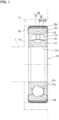
- the rolling bearing 10 (either a first or a second rolling bearing 10) according to the first embodiment is disposed between a shaft 1 and a housing 2 surrounding the shaft 1.
- the shaft 1 rotates relative to the housing 2.
- the shaft 1 is, for example, the rotary shaft of a motor of an electric vehicle (EV).
- the shaft 1 has cylindrical fitting surfaces 1a extending in the circumferential direction.
- the housing 2 is stationary relative to the shaft 1, and supports the shaft 1 through the rolling bearing 10.
- the housing 2 is, for example, a partition wall forming a portion of a case of the above-described motor.
- the housing 2 has a cylindrical fitting surface 2a extending in the circumferential direction. This fitting surface 2a is concentric with the corresponding fitting surface 1a of the shaft 1.
- the rolling bearing 10 supports the shaft 1 for rotation relative to the housing 2, and bears, for example, radial loads that act between the shaft 1 and the housing 2.
- the EV motor shown in Fig. 2 includes the housing 2, which defines the outer perimeter of the motor; the shaft 1, which is inserted in the housing 2; and a rotor 5 mounted around the shaft 1 for rotation in unison with the shaft 1.
- a stator 6 is fixed to the inner side of the housing 2.
- a coil is mounted in the stator 6 and electricity is supplied to the coil via a lead wire 7.
- a flange bracket 3 is mounted to an opening of the housing 2.
- the shaft 1 extends through a center hole of the flange bracket 3.
- the flange bracket 3 has a cylindrical fitting surface 3a extending in the circumferential direction. This fitting surface 3a is also concentric with the corresponding fitting surface 1a of the shaft 1.
- the first rolling bearing 10 is disposed between the fitting surface 2a of the housing 2 on the bottom side (i.e., right side in Fig. 1 ) of the housing 2 and the corresponding fitting surface 1a of the shaft 1.
- the second rolling bearing 10 is disposed between the fitting surface 3a of the flange bracket 3 and the corresponding fitting surface 1a of the shaft 1.
- the rolling bearings 10 each include an inner ring 11 mounted on the shaft 1, an outer ring 12 mounted to the housing 2 or the flange bracket 3, a plurality of rolling elements 13 disposed between the inner ring 11 and the outer ring 12, and a retainer 14 maintaining the circumferential distances between the rolling elements 13.
- the rolling bearings 10 shown are deep groove ball bearings.
- the inner ring 11 is an annular bearing part having, on the outer periphery thereof, a raceway surface 11a extending in the circumferential direction, and on the inner periphery thereof, a radially inner surface 11b extending in the circumferential direction.
- the radially inner surface 11b is a cylindrical surface concentric with the fitting surface 1a of the shaft 1.
- the radially inner surface 11b of the inner ring 11 is fitted to the fitting surface 1a of the shaft 1.
- the fit between the radially inner surface 11b of the inner ring 11 and the fitting surface 1a of the shaft 1 is an interference fit. Due to the interference fit, the inner ring 11 is fixed to the shaft 1 for rotation in unison with the shaft 1.
- the outer ring 12 is an annular bearing part having, on the inner periphery thereof, a raceway surface 12a extending in the circumferential direction, and on the outer periphery thereof, a radially outer surface 12b extending in the circumferential direction.
- the radially outer surface 12b is a cylindrical surface concentric with the radially inner surface 11b of the inner ring 11.
- the outer ring 12 is in a clearance fit with the housing 2.
- the inner ring 11 and the outer ring 12 are both composed of steel such as SUJ2, SCM420, SCr420, SCR420 or SUS440.
- the inner ring 11 and the outer ring 12 are subjected to an appropriate treatment such as a quench and temper treatment, a carburizing treatment, or a carbonitriding treatment.
- the radially outer surface 12b of the outer ring 12 is covered with a coating layer 30.
- the coating layer 30 is a coating layer composite 30 comprising a plurality of layers.
- the surface layer at the radially outermost position is composed of an anti-creep film 31 having lubricity.
- the radially outer surface of this anti-creep film 31 serves as a fitting surface which is in a clearance fit with the fitting surface 2a of the housing 2 or the fitting surface 3a of the flange bracket 3.
- the anti-creep film 31 may be, for example, a calcined film containing a resin binder and a solid lubricant.
- the resin binder is composed of a base material and a hardening agent and hardened by reacting the hardening agent. By solidifying the outside of the solid lubricant with the resin binder, the anti-creep film exhibits excellent adhesion properties and wear resistance.
- the anti-creep film also reduces wear of the housing 2 or the flange bracket 3.
- As the base material due to its durability, a polyamideimide resin is preferable.
- As the hardening agent for easy hardening, an epoxy resin and a reactive compound to be reacted with the epoxy resin are preferably used in combination.
- the type of the epoxy resin used is not particularly limited provided it can be used as a hardening agent, such epoxy resins including bisphenol A epoxy resin, cresol novolac epoxy resin, biphenyl epoxy resin, brominated epoxy resin, and alicyclic epoxy resin.
- the reactive compound include aliphatic polyamine, polyaminoamide, polymercaptans, aromatic polyamine, acid anhydrides, and dicyandiamide.
- a hardening accelerator may be added for increased reactivity.
- the hardening accelerator include tertiary amines, tertiary amine salts, imidazole, phosphine, phosphonium salts and sulphonium salts.
- the solid lubricant In order for the solid lubricant to exhibit lubricity, it is preferably composed of a material softer than the material forming the housing 2, specifically a material having a hardness of Hv 50 to 150.
- the solid lubricant material includes molybdenum disulfide powder, graphite powder, tungsten disulfide, and polytetrafluoroethylene. Among them, preferably, molybdenum disulfide may be used alone, or a mixture of molybdenum disulfide and another or other materials may be used.
- the anti-creep film 31 may further contain a friction/wear adjustor.
- the friction/wear adjustor is a material that improves the wear resistance of the calcined film, and is preferably selected from materials softer than the material forming the housing 2. Examples of such materials include antimony oxide, talc, mica, potassium titanate, tin, copper, zinc and nickel. Among them, antimony oxide is particularly preferable.
- a coating liquid is prepared by, for example, adding solid lubricant powder, friction/wear adjuster powder, and other components to a solvent into which the resin binder is dissolved.
- the coating liquid thus obtained is applied to the surface of the below-described insulating film or another intermediate film, and is heated to evaporate the solvent, thereby forming the anti-creep film 31.
- At least one of the layers forming the coating layer composite 30 other than the anti-creep film 31 comprises an insulating film 32 having insulating properties.
- the insulating film 32 is formed on the outer periphery of the radially outer surface 12b, and the anti-creep film 31 is formed outside of the insulating film 32.
- the insulating film 32 is composed of a material having insulating properties.
- the insulating film 32 provides insulation between the radially outer surface 12b of the outer ring 12 and the fitting surface 2a, 3a of the housing 2 or the flange bracket 3 to prevent leak current from the fitting surface 2a, 3a from reaching the radially outer surface 12b.
- Examples of the material of the insulating film 32 include a ceramic material, an epoxy resin, and a polyamideimide resin. If a ceramic material, an epoxy resin, or a polyamideimide resin is used, the calcined film may be formed by heating the coated material. If an epoxy resin or a polyamideimide resin is used, calcining may be performed together with a hardening agent.
- the insulating film 32 shown includes a center covering portion 32a covering the radially outer surface 12b of the outer ring 12, a side covering portion 32b covering a side surface 12c of the outer ring 12.
- the side surface 12c of the outer ring 12 is one of two side surfaces defining the width of the outer ring 12.
- the side surface 12c axially opposes the side surface of the housing 2 or the flange bracket 3.
- the center covering portion 32a and the side covering portions 32b form an integral film.
- the side covering portion 32b provides insulation between the housing 2 or the flange bracket 3 and the side surface 12c of the outer ring 12, and by preventing discharge therebetween, the electrolytic corrosion of the housing 2 or the flange bracket 3 and the side surface 12c is prevented.
- the anti-creep film 31 as the surface layer serves as the fitting surface with the housing 2 or the flange bracket 2, exhibiting lubricity during creeping, thereby preventing friction and wear of the radially outer surface 12b of the outer ring 12 and the fitting surface 2a, 3a of the corresponding one of the housing 2 and the flange bracket 3.
- the insulating film 32 breaks the circuit of the flow of leakage current, preventing discharge between the inner ring 11 or the outer ring 12 and the rolling elements 13, and thereby preventing electrolytic corrosion damage to the inner ring 11, the outer ring 12 and the rolling elements 13.
- the rolling bearing 10 in a use condition of the rolling bearing 10 in which leakage current reaches the inner ring 11 or the outer ring 12, and in which the inner ring 11 or the outer ring 12 is in a clearance fit, respectively, with the shaft 1 or one of the housing 2 and the flange bracket 3, the rolling bearing 10 exhibits both creep resistance and resistance to electrolytic corrosion.
- the insulating film 32 of the coating layer composite 30 includes the side covering portion 32b covering the side surface 12c of the outer ring 12, the insulating film 32 prevents discharge between the side surface 12c of the outer ring 12 and one of the housing 2 and the flange bracket 3 that opposes the side surface 12c, thereby preventing electrolytic corrosion of e.g., the side surface 12c.
- the coating layer composite 30 is not limited to the two-layer structure as shown.
- a film having a different function may be disposed between the radially outer surface 12b and the anti-creep film 31, and also, an additional insulating film and an additional anti-creep film may be laminated between the insulating film 32 and the anti-creep film 31. Since, in an environment where alternating current flows, the capacitance is involved in the electrolytic corrosion resistance performance, the films need to have a certain amount of capacitance. Since the necessary capacitance is determined by the structure of the parts, the materials and thicknesses of the films, etc., the necessary capacitance is properly determined according to the use environment.
- the second embodiment is described with reference to Fig. 3 .
- the description is limited to what differs from the first embodiment.
- the radially inner surface 11b of the inner ring 11 is covered with a coating layer composite 40 comprising a plurality of layers.
- the coating layer composite 40 includes an insulating film 41 having a center covering portion 41a covering the radially inner surface 11b of the inner ring 11, and a side covering portion 41b covering a side surface 11c of the inner ring 11.
- the side surface 11c is one of two side surfaces defining the width of the inner ring 11.
- the side surface 11c axially opposes the side surface of the housing 2 or the flange bracket 3.
- the coating layer composite 40 further includes an anti-creep film 42, as a surface layer of the coating layer composite 40, which forms a fitting surface fitted to the fitting surface 1a of the shaft 1.
- the anti-creep film 41 exhibits anti-creep properties against the shaft 1.
- the insulating film 41 and the anti-creep film 42 may have the same structures and may be formed by the same methods, as the insulating film and the anti-creep film of the first embodiment.
- the coating layer composite 40 further includes an intermediate layer 43 between the insulating film 41 and the anti-creep film 42.
- the anti-creep film 42 is formed, as the surface layer, on the front side of the intermediate layer 43.
- the structure of the intermediate layer 43 is not particularly limited provided it does not interfere with the performances of the insulating film 41 and the anti-creep film 42.
- it may have the capability of improving insulating properties, have the capability of strongly fixing the anti-creep film 42 in position, or may have other properties.
- an intermediate layer 43 that shows good adhesion to both of them may be used. If the insulating film 41 and the anti-creep film 42 alone are not capable of achieving the required capacitance, an intermediate layer 43 may be selected which enables, in combination of the three, to achieve the required capacitance.
- the intermediate layer 43 may be formed not only between the insulating film 41 and the anti-creep film 42 but also between the insulating film 41 and the inner ring 11.
- the intermediate layer 43 may have, instead of the single-layer structure, a multi-layer structure.
- the insulating film 41 breaks the circuit of the flow of leakage current, thereby preventing electrolytic corrosion damage to the inner ring 11, the outer ring 12, and the rolling elements 13 by preventing discharge between the inner ring 11 or the outer ring and the rolling elements 13, and also preventing the electrolytic corrosion of, for example, the side surface 11c by preventing discharge between the side surface 11c of the inner ring 11 and one of the housing 2 and the flange bracket 3 that opposes the side surface 11c of the inner ring 11.
- the third embodiment is described with reference to Fig, 4 .
- the third embodiment differs from the second embodiment in that the anti-creep film 42 includes an extended covering portion 42b covering a portion of the inner ring 11 other than its radially inner surface 11b, and in contact with the housing 2.
- the center covering portion 43a of the intermediate layer 43 is superposed on the center covering portion 41a of the insulating film 41, while the center covering portion 42a of the anti-creep film 42 is superposed on the center covering portion 43a of the intermediate layer 43.
- the side covering portion 43b of the intermediate layer 43 is superposed on the side covering portion 41b of the insulating film 41, while the extended covering portion 42b of the anti-creep film 42 is superposed on the side covering portion 43b of the intermediate layer 43.
- the extended covering portion 42b of the anti-creep film 42 slides on the side surface of the housing 2 in the circumferential direction.
- the extended covering portion 42b prevents friction and wear between the side surface 11c of the inner ring 11 and the housing 2.
- the anti-creep film 42 of the coating layer composite 40 includes an extended covering portion 42b covering a portion of the inner ring 11 other than its radially inner surface 11b (i.e., side surface 11c), and in contact with the housing 2, the extended covering portion 42b prevents wear and friction between the above inner ring portion (side surface 11c) and the housing 2.
- the extended covering portion 42b may be superposed on this outer peripheral portion.
- the coating layer composite in which the coating layer composite is formed on the outer ring 12, the coating layer composite may include a portion corresponding to the extended covering portion, thereby preventing friction and wear between the side surface of the outer ring and the shaft.
- the outer ring of the first embodiment may be used, or the outer ring may be free of the coating layer composite.
Landscapes
- Engineering & Computer Science (AREA)
- General Engineering & Computer Science (AREA)
- Mechanical Engineering (AREA)
- Manufacturing & Machinery (AREA)
- Rolling Contact Bearings (AREA)
- Mounting Of Bearings Or Others (AREA)
Applications Claiming Priority (2)
| Application Number | Priority Date | Filing Date | Title |
|---|---|---|---|
| JP2020147432A JP2022042162A (ja) | 2020-09-02 | 2020-09-02 | 転がり軸受 |
| PCT/JP2021/031325 WO2022050165A1 (fr) | 2020-09-02 | 2021-08-26 | Roulement à rouleaux |
Publications (3)
| Publication Number | Publication Date |
|---|---|
| EP4209689A1 true EP4209689A1 (fr) | 2023-07-12 |
| EP4209689A4 EP4209689A4 (fr) | 2024-02-07 |
| EP4209689B1 EP4209689B1 (fr) | 2025-03-05 |
Family
ID=80490964
Family Applications (1)
| Application Number | Title | Priority Date | Filing Date |
|---|---|---|---|
| EP21864223.9A Active EP4209689B1 (fr) | 2020-09-02 | 2021-08-26 | Roulement à rouleaux |
Country Status (6)
| Country | Link |
|---|---|
| US (1) | US12241504B2 (fr) |
| EP (1) | EP4209689B1 (fr) |
| JP (2) | JP2022042162A (fr) |
| KR (1) | KR20230086661A (fr) |
| CN (1) | CN115917172A (fr) |
| WO (1) | WO2022050165A1 (fr) |
Families Citing this family (10)
| Publication number | Priority date | Publication date | Assignee | Title |
|---|---|---|---|---|
| CN117685292A (zh) * | 2022-09-05 | 2024-03-12 | 斯凯孚公司 | 球轴承和球轴承组件 |
| KR20240130238A (ko) * | 2023-02-21 | 2024-08-29 | 주식회사 베어링아트 | 전식 방지 베어링 및 그 제조 방법 |
| JP2024140311A (ja) | 2023-03-28 | 2024-10-10 | パーカー熱処理工業株式会社 | 金属部品に絶縁皮膜と固体潤滑皮膜とを被覆する方法 |
| DE102023207106A1 (de) | 2023-07-26 | 2025-01-30 | Aktiebolaget Skf | Wälzlager und Verfahren zur dessen Herstellung |
| DE102023207109A1 (de) | 2023-07-26 | 2025-01-30 | Aktiebolaget Skf | Wälzlager und Verfahren zur dessen Herstellung |
| DE102023207105A1 (de) * | 2023-07-26 | 2025-01-30 | Aktiebolaget Skf | Wälzlager und Verfahren zu dessen Herstellung |
| DE102023207102A1 (de) | 2023-07-26 | 2025-01-30 | Aktiebolaget Skf | Wälzlager und Verfahren zu dessen Herstellung |
| EP4559984A4 (fr) * | 2023-10-04 | 2025-10-08 | Daikin Ind Ltd | Composition de revêtement, film, article et palier |
| JP2025150638A (ja) * | 2024-03-27 | 2025-10-09 | Ntn株式会社 | 転がり軸受 |
| DE102024113735A1 (de) * | 2024-05-16 | 2025-11-20 | Schaeffler Technologies AG & Co. KG | Wälzlagerelement, Windkraftanlage und Verfahren zum Beschichten eines Wälzlagerelementes |
Family Cites Families (17)
| Publication number | Priority date | Publication date | Assignee | Title |
|---|---|---|---|---|
| JPS5510111A (en) | 1978-07-04 | 1980-01-24 | Nippon Seiko Kk | Roller bearing for preventing electrolytic corrosion |
| JPS6085626A (ja) | 1983-10-17 | 1985-05-15 | Mitsubishi Electric Corp | 復号装置 |
| JPS6085626U (ja) | 1983-11-11 | 1985-06-13 | 光洋精工株式会社 | ころがり軸受 |
| JPH0548118Y2 (fr) | 1986-08-28 | 1993-12-20 | ||
| JP2571594B2 (ja) * | 1988-01-14 | 1997-01-16 | エヌティエヌ株式会社 | 電食防止型転がり軸受 |
| JPH0653824A (ja) | 1992-07-30 | 1994-02-25 | Nec Corp | 位相同期発振器 |
| JPH0653824U (ja) * | 1992-09-14 | 1994-07-22 | 日本精工株式会社 | 電食防止形転がり軸受 |
| JP2002048145A (ja) * | 2000-08-04 | 2002-02-15 | Ntn Corp | 電食防止型転がり軸受 |
| JP2002266870A (ja) * | 2001-03-06 | 2002-09-18 | Nsk Ltd | 転がり軸受とその製造方法及び回転機械装置 |
| JP2007292119A (ja) * | 2006-04-21 | 2007-11-08 | Ntn Corp | 軸受、転動部材および転動部材の製造方法 |
| JP2008095884A (ja) * | 2006-10-13 | 2008-04-24 | Ntn Corp | 絶縁転がり軸受 |
| JP2013036596A (ja) * | 2011-08-11 | 2013-02-21 | Ntn Corp | 円すいころ軸受およびその取付構造 |
| JP2013199954A (ja) | 2012-03-23 | 2013-10-03 | Nsk Ltd | 電食防止用絶縁転がり軸受 |
| JP6724415B2 (ja) * | 2016-02-26 | 2020-07-15 | 株式会社ジェイテクト | 車輪用軸受装置 |
| US10794427B2 (en) * | 2016-04-05 | 2020-10-06 | Schaeffler Technologies AG & Co. KG | Bearing ring with insulating coating |
| CN109642615B (zh) * | 2016-08-26 | 2020-09-22 | 日本精工株式会社 | 滚动轴承及其制造方法 |
| JP2019138467A (ja) * | 2018-02-07 | 2019-08-22 | 株式会社ジェイテクト | 電食防止軸受 |
-
2020
- 2020-09-02 JP JP2020147432A patent/JP2022042162A/ja active Pending
-
2021
- 2021-08-26 CN CN202180051792.3A patent/CN115917172A/zh active Pending
- 2021-08-26 EP EP21864223.9A patent/EP4209689B1/fr active Active
- 2021-08-26 KR KR1020237008496A patent/KR20230086661A/ko active Pending
- 2021-08-26 US US18/024,153 patent/US12241504B2/en active Active
- 2021-08-26 WO PCT/JP2021/031325 patent/WO2022050165A1/fr not_active Ceased
-
2025
- 2025-07-08 JP JP2025115046A patent/JP2025129410A/ja active Pending
Also Published As
| Publication number | Publication date |
|---|---|
| JP2025129410A (ja) | 2025-09-04 |
| EP4209689B1 (fr) | 2025-03-05 |
| WO2022050165A1 (fr) | 2022-03-10 |
| KR20230086661A (ko) | 2023-06-15 |
| JP2022042162A (ja) | 2022-03-14 |
| CN115917172A (zh) | 2023-04-04 |
| EP4209689A4 (fr) | 2024-02-07 |
| US12241504B2 (en) | 2025-03-04 |
| US20230272820A1 (en) | 2023-08-31 |
Similar Documents
| Publication | Publication Date | Title |
|---|---|---|
| EP4209689B1 (fr) | Roulement à rouleaux | |
| ES2927454T3 (es) | Cojinete y conjunto de bisagra | |
| US11002315B2 (en) | Rolling bearing having electrical insulating material, and manufacturing process of such rolling bearing | |
| CN102630281B (zh) | 用于公差环控制的组件 | |
| US11005334B2 (en) | Annular member, method, and assembly for component displacement control | |
| US11898608B2 (en) | Tolerance ring, method, and assembly for component retention control | |
| US10082173B2 (en) | Sliding element comprising at least one coupling element | |
| CN103518070A (zh) | 具有可转变的导电态的衬套 | |
| US11873865B2 (en) | Tolerance ring and assembly | |
| US20220389971A1 (en) | Bearing assembly | |
| JP2025157300A (ja) | 押し込み式締結具、アセンブリ、ならびにその製造および使用方法 | |
| US10926789B2 (en) | Steering assembly | |
| US10933904B2 (en) | Steering assembly | |
| US11378124B2 (en) | Clip, clip assembly, and method of making and using the same | |
| JPH04210124A (ja) | 電気絶縁軸受 | |
| TW201915351A (zh) | 軸承總成以及其製造及使用方法 | |
| JP2025021505A (ja) | 電食防止通電カバーおよび転がり軸受 | |
| US20260085723A1 (en) | Bearing device with integrated electrical insulation, notably for an electric motor or machine, and associated manufacturing methods | |
| WO2026042817A1 (fr) | Unité de transport de courant et unité de palier | |
| JP2025127164A (ja) | 通電ユニットおよび軸受ユニット | |
| JP2019215033A (ja) | 転がり軸受 |
Legal Events
| Date | Code | Title | Description |
|---|---|---|---|
| STAA | Information on the status of an ep patent application or granted ep patent |
Free format text: STATUS: THE INTERNATIONAL PUBLICATION HAS BEEN MADE |
|
| PUAI | Public reference made under article 153(3) epc to a published international application that has entered the european phase |
Free format text: ORIGINAL CODE: 0009012 |
|
| STAA | Information on the status of an ep patent application or granted ep patent |
Free format text: STATUS: REQUEST FOR EXAMINATION WAS MADE |
|
| 17P | Request for examination filed |
Effective date: 20230301 |
|
| AK | Designated contracting states |
Kind code of ref document: A1 Designated state(s): AL AT BE BG CH CY CZ DE DK EE ES FI FR GB GR HR HU IE IS IT LI LT LU LV MC MK MT NL NO PL PT RO RS SE SI SK SM TR |
|
| DAV | Request for validation of the european patent (deleted) | ||
| DAX | Request for extension of the european patent (deleted) | ||
| A4 | Supplementary search report drawn up and despatched |
Effective date: 20240109 |
|
| RIC1 | Information provided on ipc code assigned before grant |
Ipc: F16C 35/07 20060101ALI20240103BHEP Ipc: F16C 33/64 20060101ALI20240103BHEP Ipc: F16C 19/06 20060101AFI20240103BHEP |
|
| GRAP | Despatch of communication of intention to grant a patent |
Free format text: ORIGINAL CODE: EPIDOSNIGR1 |
|
| STAA | Information on the status of an ep patent application or granted ep patent |
Free format text: STATUS: GRANT OF PATENT IS INTENDED |
|
| INTG | Intention to grant announced |
Effective date: 20241024 |
|
| GRAS | Grant fee paid |
Free format text: ORIGINAL CODE: EPIDOSNIGR3 |
|
| GRAA | (expected) grant |
Free format text: ORIGINAL CODE: 0009210 |
|
| STAA | Information on the status of an ep patent application or granted ep patent |
Free format text: STATUS: THE PATENT HAS BEEN GRANTED |
|
| AK | Designated contracting states |
Kind code of ref document: B1 Designated state(s): AL AT BE BG CH CY CZ DE DK EE ES FI FR GB GR HR HU IE IS IT LI LT LU LV MC MK MT NL NO PL PT RO RS SE SI SK SM TR |
|
| REG | Reference to a national code |
Ref country code: GB Ref legal event code: FG4D |
|
| REG | Reference to a national code |
Ref country code: CH Ref legal event code: EP |
|
| REG | Reference to a national code |
Ref country code: DE Ref legal event code: R096 Ref document number: 602021027314 Country of ref document: DE |
|
| REG | Reference to a national code |
Ref country code: IE Ref legal event code: FG4D |
|
| PG25 | Lapsed in a contracting state [announced via postgrant information from national office to epo] |
Ref country code: RS Free format text: LAPSE BECAUSE OF FAILURE TO SUBMIT A TRANSLATION OF THE DESCRIPTION OR TO PAY THE FEE WITHIN THE PRESCRIBED TIME-LIMIT Effective date: 20250605 |
|
| PG25 | Lapsed in a contracting state [announced via postgrant information from national office to epo] |
Ref country code: FI Free format text: LAPSE BECAUSE OF FAILURE TO SUBMIT A TRANSLATION OF THE DESCRIPTION OR TO PAY THE FEE WITHIN THE PRESCRIBED TIME-LIMIT Effective date: 20250305 |
|
| REG | Reference to a national code |
Ref country code: NL Ref legal event code: MP Effective date: 20250305 |
|
| PG25 | Lapsed in a contracting state [announced via postgrant information from national office to epo] |
Ref country code: ES Free format text: LAPSE BECAUSE OF FAILURE TO SUBMIT A TRANSLATION OF THE DESCRIPTION OR TO PAY THE FEE WITHIN THE PRESCRIBED TIME-LIMIT Effective date: 20250305 |
|
| REG | Reference to a national code |
Ref country code: LT Ref legal event code: MG9D |
|
| PG25 | Lapsed in a contracting state [announced via postgrant information from national office to epo] |
Ref country code: NO Free format text: LAPSE BECAUSE OF FAILURE TO SUBMIT A TRANSLATION OF THE DESCRIPTION OR TO PAY THE FEE WITHIN THE PRESCRIBED TIME-LIMIT Effective date: 20250605 |
|
| PG25 | Lapsed in a contracting state [announced via postgrant information from national office to epo] |
Ref country code: HR Free format text: LAPSE BECAUSE OF FAILURE TO SUBMIT A TRANSLATION OF THE DESCRIPTION OR TO PAY THE FEE WITHIN THE PRESCRIBED TIME-LIMIT Effective date: 20250305 |
|
| PG25 | Lapsed in a contracting state [announced via postgrant information from national office to epo] |
Ref country code: LV Free format text: LAPSE BECAUSE OF FAILURE TO SUBMIT A TRANSLATION OF THE DESCRIPTION OR TO PAY THE FEE WITHIN THE PRESCRIBED TIME-LIMIT Effective date: 20250305 |
|
| PG25 | Lapsed in a contracting state [announced via postgrant information from national office to epo] |
Ref country code: GR Free format text: LAPSE BECAUSE OF FAILURE TO SUBMIT A TRANSLATION OF THE DESCRIPTION OR TO PAY THE FEE WITHIN THE PRESCRIBED TIME-LIMIT Effective date: 20250606 Ref country code: BG Free format text: LAPSE BECAUSE OF FAILURE TO SUBMIT A TRANSLATION OF THE DESCRIPTION OR TO PAY THE FEE WITHIN THE PRESCRIBED TIME-LIMIT Effective date: 20250305 |
|
| REG | Reference to a national code |
Ref country code: AT Ref legal event code: MK05 Ref document number: 1773165 Country of ref document: AT Kind code of ref document: T Effective date: 20250305 |
|
| PG25 | Lapsed in a contracting state [announced via postgrant information from national office to epo] |
Ref country code: NL Free format text: LAPSE BECAUSE OF FAILURE TO SUBMIT A TRANSLATION OF THE DESCRIPTION OR TO PAY THE FEE WITHIN THE PRESCRIBED TIME-LIMIT Effective date: 20250305 |
|
| PG25 | Lapsed in a contracting state [announced via postgrant information from national office to epo] |
Ref country code: SE Free format text: LAPSE BECAUSE OF FAILURE TO SUBMIT A TRANSLATION OF THE DESCRIPTION OR TO PAY THE FEE WITHIN THE PRESCRIBED TIME-LIMIT Effective date: 20250305 |
|
| PG25 | Lapsed in a contracting state [announced via postgrant information from national office to epo] |
Ref country code: SM Free format text: LAPSE BECAUSE OF FAILURE TO SUBMIT A TRANSLATION OF THE DESCRIPTION OR TO PAY THE FEE WITHIN THE PRESCRIBED TIME-LIMIT Effective date: 20250305 |
|
| PG25 | Lapsed in a contracting state [announced via postgrant information from national office to epo] |
Ref country code: PT Free format text: LAPSE BECAUSE OF FAILURE TO SUBMIT A TRANSLATION OF THE DESCRIPTION OR TO PAY THE FEE WITHIN THE PRESCRIBED TIME-LIMIT Effective date: 20250707 |
|
| PGFP | Annual fee paid to national office [announced via postgrant information from national office to epo] |
Ref country code: DE Payment date: 20250828 Year of fee payment: 5 |
|
| PG25 | Lapsed in a contracting state [announced via postgrant information from national office to epo] |
Ref country code: IT Free format text: LAPSE BECAUSE OF FAILURE TO SUBMIT A TRANSLATION OF THE DESCRIPTION OR TO PAY THE FEE WITHIN THE PRESCRIBED TIME-LIMIT Effective date: 20250305 Ref country code: PL Free format text: LAPSE BECAUSE OF FAILURE TO SUBMIT A TRANSLATION OF THE DESCRIPTION OR TO PAY THE FEE WITHIN THE PRESCRIBED TIME-LIMIT Effective date: 20250305 |
|
| PG25 | Lapsed in a contracting state [announced via postgrant information from national office to epo] |
Ref country code: AT Free format text: LAPSE BECAUSE OF FAILURE TO SUBMIT A TRANSLATION OF THE DESCRIPTION OR TO PAY THE FEE WITHIN THE PRESCRIBED TIME-LIMIT Effective date: 20250305 |
|
| PGFP | Annual fee paid to national office [announced via postgrant information from national office to epo] |
Ref country code: FR Payment date: 20250826 Year of fee payment: 5 |
|
| PG25 | Lapsed in a contracting state [announced via postgrant information from national office to epo] |
Ref country code: CZ Free format text: LAPSE BECAUSE OF FAILURE TO SUBMIT A TRANSLATION OF THE DESCRIPTION OR TO PAY THE FEE WITHIN THE PRESCRIBED TIME-LIMIT Effective date: 20250305 Ref country code: EE Free format text: LAPSE BECAUSE OF FAILURE TO SUBMIT A TRANSLATION OF THE DESCRIPTION OR TO PAY THE FEE WITHIN THE PRESCRIBED TIME-LIMIT Effective date: 20250305 |
|
| PG25 | Lapsed in a contracting state [announced via postgrant information from national office to epo] |
Ref country code: RO Free format text: LAPSE BECAUSE OF FAILURE TO SUBMIT A TRANSLATION OF THE DESCRIPTION OR TO PAY THE FEE WITHIN THE PRESCRIBED TIME-LIMIT Effective date: 20250305 |
|
| PG25 | Lapsed in a contracting state [announced via postgrant information from national office to epo] |
Ref country code: SK Free format text: LAPSE BECAUSE OF FAILURE TO SUBMIT A TRANSLATION OF THE DESCRIPTION OR TO PAY THE FEE WITHIN THE PRESCRIBED TIME-LIMIT Effective date: 20250305 |
|
| PG25 | Lapsed in a contracting state [announced via postgrant information from national office to epo] |
Ref country code: IS Free format text: LAPSE BECAUSE OF FAILURE TO SUBMIT A TRANSLATION OF THE DESCRIPTION OR TO PAY THE FEE WITHIN THE PRESCRIBED TIME-LIMIT Effective date: 20250705 |
|
| REG | Reference to a national code |
Ref country code: DE Ref legal event code: R097 Ref document number: 602021027314 Country of ref document: DE |
|
| PLBE | No opposition filed within time limit |
Free format text: ORIGINAL CODE: 0009261 |
|
| STAA | Information on the status of an ep patent application or granted ep patent |
Free format text: STATUS: NO OPPOSITION FILED WITHIN TIME LIMIT |
|
| PG25 | Lapsed in a contracting state [announced via postgrant information from national office to epo] |
Ref country code: DK Free format text: LAPSE BECAUSE OF FAILURE TO SUBMIT A TRANSLATION OF THE DESCRIPTION OR TO PAY THE FEE WITHIN THE PRESCRIBED TIME-LIMIT Effective date: 20250305 |
|
| REG | Reference to a national code |
Ref country code: CH Ref legal event code: L10 Free format text: ST27 STATUS EVENT CODE: U-0-0-L10-L00 (AS PROVIDED BY THE NATIONAL OFFICE) Effective date: 20260114 |
|
| 26N | No opposition filed |
Effective date: 20251208 |
|
| REG | Reference to a national code |
Ref country code: CH Ref legal event code: H13 Free format text: ST27 STATUS EVENT CODE: U-0-0-H10-H13 (AS PROVIDED BY THE NATIONAL OFFICE) Effective date: 20260324 |
|
| PG25 | Lapsed in a contracting state [announced via postgrant information from national office to epo] |
Ref country code: MC Free format text: LAPSE BECAUSE OF FAILURE TO SUBMIT A TRANSLATION OF THE DESCRIPTION OR TO PAY THE FEE WITHIN THE PRESCRIBED TIME-LIMIT Effective date: 20250305 |
|
| PG25 | Lapsed in a contracting state [announced via postgrant information from national office to epo] |
Ref country code: LU Free format text: LAPSE BECAUSE OF NON-PAYMENT OF DUE FEES Effective date: 20250826 |
|
| PG25 | Lapsed in a contracting state [announced via postgrant information from national office to epo] |
Ref country code: CH Free format text: LAPSE BECAUSE OF NON-PAYMENT OF DUE FEES Effective date: 20250831 |