EP4209703A1 - Outil d'alignement de tuyaux - Google Patents
Outil d'alignement de tuyaux Download PDFInfo
- Publication number
- EP4209703A1 EP4209703A1 EP23150863.1A EP23150863A EP4209703A1 EP 4209703 A1 EP4209703 A1 EP 4209703A1 EP 23150863 A EP23150863 A EP 23150863A EP 4209703 A1 EP4209703 A1 EP 4209703A1
- Authority
- EP
- European Patent Office
- Prior art keywords
- pipe
- tool
- recesses
- recess
- laser
- Prior art date
- Legal status (The legal status is an assumption and is not a legal conclusion. Google has not performed a legal analysis and makes no representation as to the accuracy of the status listed.)
- Granted
Links
Images

Classifications
-
- F—MECHANICAL ENGINEERING; LIGHTING; HEATING; WEAPONS; BLASTING
- F16—ENGINEERING ELEMENTS AND UNITS; GENERAL MEASURES FOR PRODUCING AND MAINTAINING EFFECTIVE FUNCTIONING OF MACHINES OR INSTALLATIONS; THERMAL INSULATION IN GENERAL
- F16L—PIPES; JOINTS OR FITTINGS FOR PIPES; SUPPORTS FOR PIPES, CABLES OR PROTECTIVE TUBING; MEANS FOR THERMAL INSULATION IN GENERAL
- F16L1/00—Laying or reclaiming pipes; Repairing or joining pipes on or under water
- F16L1/024—Laying or reclaiming pipes on land, e.g. above the ground
- F16L1/06—Accessories therefor, e.g. anchors
- F16L1/10—Accessories therefor, e.g. anchors for aligning
-
- G—PHYSICS
- G01—MEASURING; TESTING
- G01C—MEASURING DISTANCES, LEVELS OR BEARINGS; SURVEYING; NAVIGATION; GYROSCOPIC INSTRUMENTS; PHOTOGRAMMETRY OR VIDEOGRAMMETRY
- G01C15/00—Surveying instruments or accessories not provided for in groups G01C1/00 - G01C13/00
- G01C15/10—Plumb lines
- G01C15/105—Optical plumbing
-
- F—MECHANICAL ENGINEERING; LIGHTING; HEATING; WEAPONS; BLASTING
- F16—ENGINEERING ELEMENTS AND UNITS; GENERAL MEASURES FOR PRODUCING AND MAINTAINING EFFECTIVE FUNCTIONING OF MACHINES OR INSTALLATIONS; THERMAL INSULATION IN GENERAL
- F16L—PIPES; JOINTS OR FITTINGS FOR PIPES; SUPPORTS FOR PIPES, CABLES OR PROTECTIVE TUBING; MEANS FOR THERMAL INSULATION IN GENERAL
- F16L55/00—Devices or appurtenances for use in, or in connection with, pipes or pipe systems
-
- B—PERFORMING OPERATIONS; TRANSPORTING
- B25—HAND TOOLS; PORTABLE POWER-DRIVEN TOOLS; MANIPULATORS
- B25H—WORKSHOP EQUIPMENT, e.g. FOR MARKING-OUT WORK; STORAGE MEANS FOR WORKSHOPS
- B25H7/00—Marking-out or setting-out work
- B25H7/005—Marking-out or setting-out work for pipes
-
- E—FIXED CONSTRUCTIONS
- E03—WATER SUPPLY; SEWERAGE
- E03C—DOMESTIC PLUMBING INSTALLATIONS FOR FRESH WATER OR WASTE WATER; SINKS
- E03C1/00—Domestic plumbing installations for fresh water or waste water; Sinks
- E03C1/02—Plumbing installations for fresh water
- E03C2001/028—Alignment aids for plumbing installations
Definitions
- the present invention relates to an alignment tool for a pipe.
- a pipe alignment tool for a pipe having a bore with a central axis comprising a main body having one end conforming with an open end of the pipe in use, and an opposite end having mounted therein a sighting means, wherein the sighting means is configured to discharge a sighting beam coaxially with the central axis of the pipe, and wherein the end of the tool conforming with an open end of the pipe is formed with a plurality of continuous concentric recesses, one of the plurality of continuous concentric recesses receiving the open end of the pipe therein in use, each of the continuous concentric recesses making up the plurality of continuous concentric recesses having predetermined dimensions which match the outside and the inside of the pipe in use.
- the pipe alignment tool according to the invention is advantageous primarily because in use the sighting means discharges the sighting beam coaxially with the central axis of the pipe on to which the tool is mounted. Therefore it is possible to sight where the centre of an existing pipe will engage with a wall or feature some distance away. The operator then knows where to place a hole or a device the pipe is to connect to accurately and very quickly.
- the pipe alignment tool also has the advantage that the tool body can fit over the end of the pipe and is held rigidly in place by virtue of the plurality of continuous concentric recesses having walls which match the outside and the inside of the pipe. Thus, in use, there is no scope for the tool to wobble or become loose on the end of the pipe that would otherwise lead to inaccuracies in the sighting measurements.
- the main body is preferably plastic as this is the cheapest and easiest to manufacture. However main body may also be made from metal or composite material.
- the predetermined dimensions of the recesses refers to the dimensions and shape of the walls of the recess.
- the dimensions of the walls are selected prior to use by the user in manufacturing the tool based on the range of pipes that the user might want to use the tool for.
- the recesses may have standard cross sections of most standard pipe work.
- the recesses would be designed with dimensions to fit 1/2 inch (12.7mm), 7/8 inch (22.225mm), 1 1/8 inch (28.575mm) and 1 3/8 inch (34.925mm) diameter pipework, for example.
- refrigeration pipework is set at imperial diameters.
- the recesses would be designed with dimensions to fit 9mm, 12mm, 15mm, 19mm and 22mm for example. And each recess would have the thickness comparable to that of the thickness of household pipework or refrigeration pipework.
- each recess might be much larger or vary. But in each case the dimensions of each recess are predetermined based on the dimensions of the pipes being worked on and therefore the type of work being conducted.
- match means to conform with or mutually engage with so as to substantially fit. It will be understood that as most pipes are not manufactured or cut to exacting standards then some tolerance between the thickness of the recesses and the thickness of the pipe is allowed for. However this tolerance is not so large as to loosen the fit between the pipe and the tool in use. The skilled person would be capable of defining what this tolerance should be without undue effort in order that the tool can work within the above parameters. To this end the inventors have surprisingly found that with a pipe wall thickness of, for example, 1.8mm, a recess thickness of between 1.6mm and 2.0 mm would still allow the pipe to fit inside the recess. This is because of the variation and error in the manufacturer of pipework, which leads to changes in the diameter.
- the tool surprisingly still remains rigidly attached to the end of the pipe in use. So in other words, the design is such to provide a rigid attachment which caters for the small variation in pipe diameters.
- a pipe can mean a tube, pipeline, conduit, pipe fitting, box section member or channel section member.
- the pipe may be metal, plastic or composite.
- the pipe may be an electrical pipe, industrial pipe, commercial pipe or domestic pipe.
- the benefit of the plurality of continuous concentric recesses is that a single tool can be used with a plurality of pipes having different pipe dimensions. This is most often the case in industry where pipe dimensions vary greatly.
- the pipe may be any shape in cross-section. Therefore the recesses can have any shape depending on the shape of the pipe, but it is recognised that the general shape of the recesses and the general shape of the pipe cross sections must match. Examples of suitable cross sections include but are not limited to square or triangular or hexagonal, for example. Preferably the plurality of continuous concentric recesses have walls which are circular. This is because the majority of plumbing or industrial pipework has a circular cross section.
- the sighting means may be fixed permanently into the opposite end. That is to say it may be integral with the opposite end. This means that the alignment of the sighting means with respect to the body of the tool and therefore the axis of the pipe is fixed, and not open to distortion or error over time. Thus all of the alignment operations performed over time using the tool, will be accurate.
- the sighting means is removably mounted within the opposite end. This is allows it to be replaced in case of damage or requiring maintenance, or of the power of the sighting means is required to be altered.
- the sighting means may be a light emitting device, such as a lamp or laser.
- Other suitable sighting means include but are not limited to UV or Infrared emitter devices.
- the one end of the tool conforming with an open end of the pipe in use and the opposite end of the tool are removably engageable within one another. This allows interchangeability of the ends, for example if a different sighting means is required, or a different configuration of recesses is required.
- the tool comprises a main body having one end conforming with an open end of the pipe in use, and an opposite end having mounted therein a sighting means
- the opposite end necessarily projects out of the end of the pipe in use. That is to say the opposite end is some distance away from the end of the pipe in use and is not held in some way within the confines of the pipe in use.
- the benefit of this is that the user can select the relative sizes and dimensions of the sighting means and the recesses.
- the user may wish to work with sighting small bore pipe work, i.e. 5-22mm diameter for example.
- By having the opposite end with the sighting means therein some distance away from the end conforming with the open end of the pipe this is made possible. It also makes attachment and detachment of the tool to the pipe easy and without hindrance by the pipe or the recesses.
- the tool may comprise one or more spirit level bubbles mounted into the main body. This enables the user to not only to align pipework, but to maintain a specified angle for the pipe work.
- the tool may be provided as a kit of parts.
- FIG. 1 there is shown an example of the tool according to the invention.
- the tool is generally designated 1.
- the tool 1 is in two parts, a pipe part 20 and a laser part 30.
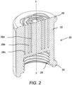
- the pipe part 20 comprises a series of recesses (generally designated 28) which are configured to receive the open end of a pipe (not shown) in use.
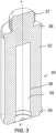
- the laser part 30 has mounted therein a battery powered laser pointer 39 (See Fig 3 ).
- the pipe part 20 and laser parts 30 are connected to one another in use by a screw thread 29, 37 ( figure 2 , 3 and 4 ). Both the pipe part 20 and the laser part 30 in this example have a circular external cross section.
- the pipe is a commercial gas pipe for refrigerant, but may alternatively be a plastic electrical conduit or steel box section tube. This example will now be described in greater detail.
- the pipe part 20, shown in cross sectional detail in figure 2 is made up of a plastic body 22.
- the body 22 itself has a distal end 24 and a proximal end 26.
- the proximal end 26 of the body 22 is formed into a plurality of continuous concentric recesses 28a, b and c.
- the recesses 28a, b and c are of increasing diameter, respectively. These diameters are predetermined based on the range of pipe diameters used for refrigeration and are respectively 5/8 inches (15.875mm) for recess 28a, 1 3/8 inches (34.925mm) for recess 28b and 2 1/8 inches (53.975mm) for recess 28c.
- Each recess 28a, b and c has straight parallel sided walls and an end wall.
- the scope of the invention herein described is not limited by these specifications and in other examples the tool is substantially the same, but with different diameter and dimensions of recesses. In another example, the tool is substantially the same, but the diameter of each recess is 5mm, 10mm and 15 mm for recess 28a, b and c, respectively.
- each recess 28a, b and c The depth of each recess 28a, b and c (i.e. the distance from the proximal end to the end wall is approximately 50 mm.
- Each recess 28a, b and c is approximately the thickness of the pipe to be inserted therein.
- the pipe has a wall thickness of 1.8mm, therefore each recess 28a, b and c has parallel side walls which are approximately 1.8mm apart, or just over to allow for a snug fit of the tool over the end of the pipe.
- the distal end 24 of the body 22 is formed into a female screw thread 29.
- the pipe part 20 has a central axis y-y which runs from the centre of the distal end 24 to the centre of the proximal end 26.
- the female screw thread 29, and the recesses 28a, b and c are all coaxial with the central axis y-y.
- the laser part 30 shown in figure 3 is made up of a plastic body 32.
- the body 32 itself has a distal end 34 and proximal end 36.
- the proximal end 36 of the body 32 is formed into a male screw thread 37 which is dimensioned to match the female thread 29 on the body 22 of the pipe part 20.
- the distal end 34 of the body 32 has a recess 38 in which is mounted a battery powered laser pointer 39.
- the recess 38 is approximately 50 mm deep in this example and 25 mm wide.
- the laser part 30 has a central axis x-x which runs from the centre of the distal end 34 to the centre of the proximal end 26.
- the male screw thread 37, the central axis of the laser pointer and the axis which the laser pointer 39 shines at in use are coaxial with the central axis x-x.
- the laser pointer 39 is retained within the recess 38 by a clamping mechanism, whereby half of the end of the distal part of the body 32 is made removable.
- this removable part is positioned back in place again and tightened onto the laser 39 using screws set in the removable part which engage with the remainder of the distal part.
- the laser 39 is clamped in place within the recess 38.
- the tool is substantially the same, but the laser 39 is retained within the recess 38 by interference fit.
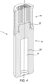
- Figure 4 shows a cross section of the arrangement of the tool 1 when the two parts 20, 30 are engaged together as described.
- a new central axis z-z which is the formation of axis x-x and y-y thereby runs through the tool 1 from the proximal end 26 of the pipe part 20 to the distal end 34 of the laser part 30.
- the tool 1 is then inserted into and over the open end of the pipe to be aligned (not shown).
- the laser is then switched on, and the laser beam shines along an extension of central axis z-z.
- This central axis z-z runs though the centre of the tool 1, it is also coaxial with the central axis of the open ended pipe. Therefore the laser beam is coaxial with the central axis of the open ended pipe.
- a user can then mark on a distant surface such as a ceiling, roof or wall, where the laser beam hits said surface. The user then knows the point on the surface where the pipe is going to align with. For example the user may need to drill a hole in the ceiling or the roof for example, and needs to know where to place the hole for the pipe to go through.
- the ceiling or roof may be some distance away from the open end of the pipe and no other reference points can be found to derive this alignment point on the ceiling or roof.
- the tool 1 the user can quickly derive the alignment point and drill the hole. The user then knows that the pipe, when extended will engage exactly with the hole in the ceiling or roof.
- the tool 1 may also be used for aligning pipes though walls or floors etc, or other materials.
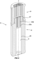
- the tool 5 is substantially as described above, (i.e. the tool 5 is in two parts), except that the laser part 30 at its proximal end 36 has a number of continuous circular recesses indicated as recesses 28d and 28e, as shown in figure 5 .
- These recesses 28d and e are substantially the same as recesses 28 a, b and c, but are of different diameters.
- Recess 28d has a diameter of 1 ⁇ 2 inch (12.7mm) and recess 28e has a diameter of 3 ⁇ 4 inches (19.05mm).
- the tool is used without the pipe part 20, and one of the recesses 28d or 28e is inserted over the end of the pipe in use, in a similar manner as described above.
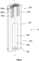
- the tool 10 is provided as a single part.
- the tool 10 comprises a plastic body 320 which is made up of a pipe portion 200 in the proximal end 360 and a laser portion 300 in the distal end 340.
- the pipe portion 200 comprises a series of continuous circular recesses 380a, 380 b and 380c which are configured to receive the open end of a pipe (not shown) in use.
- the laser portion 300 has a recess 385 mounted therein a battery powered laser pointer 390 in the same manner as described above. Both the pipe portion 200 and the laser portion 300 in this example have a circular external cross section.
- the pipe is a commercial gas pipe for refrigerant, but may alternatively be a plastic electrical conduit or steel box section tube.
- the recesses 380a, 380b and 380c in the tool 10 in figure 6 are substantially as described above for the other embodiments described herein.
- the recesses 380a, 380b and 380c are of increasing diameter respectively. These diameters are predetermined based on the range of pipe diameters used for industrial refrigeration and are respectively 1/2 inches (12.7mm) for recess 380a, 3 ⁇ 4 inches (19.05mm) for recess 380b and 1 1/8 inches (28.575mm) for recess 380c.
- Each recess 380a, 380b and 380c has straight parallel sided walls and an end wall. It will be appreciated that more than three recesses may be provided rather than just the recesses 380a, b and c shown in figure 6 in alternative examples considered.
- the tool is mounted onto the end of the pipe by engaging either of the recesses 380a, 380b or 380c with the open end of the pipe in a similar manner as described above for the other embodiments.
- the laser 390 is switched on in the same manner also and the tool 10 used and functions in the same manner as described above.
- the laser beam shines along an extension of the axis x-x which is coaxial with the central axis of the pipe to assist the user in sighting where the pipe is due to engage with a wall or ceiling some distance away.
- the tool is substantially as described above, but alternative diameters and /or dimensions of recesses are incorporated into the tool, in order to allow for different pipe diameters and/or dimensions.
- the user may need a tool for a range of metric pipe diameters and a separate tool for a range of imperial pipe diameters. With reference to the above, this can be achieved by simply replacing the pipe part 20 with a pipe part 20 adapted for a different working set of pipes.
- the tool is substantially as described above except that the recesses are of a continuous square cross section. This allows the user to use the tool with square cross section pipework.
Landscapes
- Engineering & Computer Science (AREA)
- General Engineering & Computer Science (AREA)
- Mechanical Engineering (AREA)
- Physics & Mathematics (AREA)
- General Physics & Mathematics (AREA)
- Radar, Positioning & Navigation (AREA)
- Remote Sensing (AREA)
- Length-Measuring Instruments Using Mechanical Means (AREA)
- Conveying And Assembling Of Building Elements In Situ (AREA)
- Milling Processes (AREA)
Applications Claiming Priority (1)
| Application Number | Priority Date | Filing Date | Title |
|---|---|---|---|
| GB2200214.1A GB2614569B (en) | 2022-01-10 | 2022-01-10 | Pipe alignment tool |
Publications (4)
| Publication Number | Publication Date |
|---|---|
| EP4209703A1 true EP4209703A1 (fr) | 2023-07-12 |
| EP4209703C0 EP4209703C0 (fr) | 2024-09-11 |
| EP4209703B1 EP4209703B1 (fr) | 2024-09-11 |
| EP4209703B8 EP4209703B8 (fr) | 2024-11-20 |
Family
ID=84887199
Family Applications (1)
| Application Number | Title | Priority Date | Filing Date |
|---|---|---|---|
| EP23150863.1A Active EP4209703B8 (fr) | 2022-01-10 | 2023-01-10 | Outil d'alignement de tuyaux |
Country Status (5)
| Country | Link |
|---|---|
| US (1) | US12264757B2 (fr) |
| EP (1) | EP4209703B8 (fr) |
| ES (1) | ES3003284T3 (fr) |
| GB (1) | GB2614569B (fr) |
| PL (1) | PL4209703T3 (fr) |
Families Citing this family (1)
| Publication number | Priority date | Publication date | Assignee | Title |
|---|---|---|---|---|
| US20250108500A1 (en) * | 2023-09-29 | 2025-04-03 | Michael A. Blume | System and method for placing a conduit hole in an enclosure |
Citations (3)
| Publication number | Priority date | Publication date | Assignee | Title |
|---|---|---|---|---|
| AU2019200184A1 (en) * | 2018-01-11 | 2019-07-25 | Fredrik Nilsson | A plumbing attachment to aid in the installation of piping |
| US20210190494A1 (en) * | 2019-12-20 | 2021-06-24 | Ryan Scott Lindberg | Pipe laser |
| US20220316878A1 (en) * | 2021-03-31 | 2022-10-06 | Jewett Lake Ventures, Llc | Laser Alignment Tool |
Family Cites Families (4)
| Publication number | Priority date | Publication date | Assignee | Title |
|---|---|---|---|---|
| AU2016314785A1 (en) * | 2015-09-04 | 2018-04-26 | Kyle BERRYMAN | A laser guide device |
| US20170363422A1 (en) * | 2016-06-21 | 2017-12-21 | James Pokracki | Lasergizmo |
| GB2560924A (en) * | 2017-03-28 | 2018-10-03 | Pttg Ltd | Marking guide |
| US10767985B1 (en) * | 2019-11-06 | 2020-09-08 | Harold Mays | Conduit laser alignment assembly |
-
2022
- 2022-01-10 GB GB2200214.1A patent/GB2614569B/en active Active
-
2023
- 2023-01-10 PL PL23150863.1T patent/PL4209703T3/pl unknown
- 2023-01-10 ES ES23150863T patent/ES3003284T3/es active Active
- 2023-01-10 EP EP23150863.1A patent/EP4209703B8/fr active Active
- 2023-01-10 US US18/095,027 patent/US12264757B2/en active Active
Patent Citations (3)
| Publication number | Priority date | Publication date | Assignee | Title |
|---|---|---|---|---|
| AU2019200184A1 (en) * | 2018-01-11 | 2019-07-25 | Fredrik Nilsson | A plumbing attachment to aid in the installation of piping |
| US20210190494A1 (en) * | 2019-12-20 | 2021-06-24 | Ryan Scott Lindberg | Pipe laser |
| US20220316878A1 (en) * | 2021-03-31 | 2022-10-06 | Jewett Lake Ventures, Llc | Laser Alignment Tool |
Also Published As
| Publication number | Publication date |
|---|---|
| GB2614569A (en) | 2023-07-12 |
| EP4209703B8 (fr) | 2024-11-20 |
| EP4209703C0 (fr) | 2024-09-11 |
| EP4209703B1 (fr) | 2024-09-11 |
| ES3003284T3 (en) | 2025-03-10 |
| GB2614569B (en) | 2024-07-03 |
| PL4209703T3 (pl) | 2025-02-17 |
| US20230220931A1 (en) | 2023-07-13 |
| US12264757B2 (en) | 2025-04-01 |
Similar Documents
| Publication | Publication Date | Title |
|---|---|---|
| US7793423B2 (en) | Piping alignment tool | |
| EP4209703B1 (fr) | Outil d'alignement de tuyaux | |
| US6643019B1 (en) | Laser alignment device | |
| US11946577B2 (en) | Adjustable-length water supply adapter | |
| US4076444A (en) | Drill bit extension | |
| US20080014035A1 (en) | Clamping Tool And Hole Saw Apparatus | |
| US20020038513A1 (en) | Location projector apparatus and methods | |
| CN107747934B (zh) | 顶管轴线测量方法 | |
| US8408240B2 (en) | Wall-mounted faucet that is available for water supply lines of different specifications and sizes | |
| US20130276318A1 (en) | Telescopic sight ring mounts alignment tool | |
| JP2021139491A (ja) | 配管用接続具及びこれを含む配管用接続装置 | |
| US8408241B2 (en) | Wall-mounted faucet that is available for water supply lines of different specifications and sizes | |
| US20180328684A1 (en) | Gas block alignment fixture | |
| CA2906705C (fr) | Raccord de tuyauteries | |
| RU2010128172A (ru) | Устройство для принудительной блокировки двух элементов, ориентированных перпендикулярно друг к другу | |
| KR20080006247U (ko) | 신축조절기능을 가진 배관용 커플러 | |
| JP3502816B2 (ja) | 止め座付継手 | |
| KR102574225B1 (ko) | 에어배관 시스템 및 에어배관 시스템의 시공방법 | |
| US20220257986A1 (en) | Sprinkler head adapter | |
| GB2481913A (en) | Laser marking apparatus for use in the fitting of radiators and towel rails | |
| CN220649502U (zh) | 一种水平检测装置 | |
| JP7291879B2 (ja) | 配管用標線治具 | |
| CN223701132U (zh) | 钻孔和攻牙导引器 | |
| CN218799650U (zh) | 一种丝锥加长杆 | |
| CN219810327U (zh) | 管路组件及具有其的换热器 |
Legal Events
| Date | Code | Title | Description |
|---|---|---|---|
| PUAI | Public reference made under article 153(3) epc to a published international application that has entered the european phase |
Free format text: ORIGINAL CODE: 0009012 |
|
| STAA | Information on the status of an ep patent application or granted ep patent |
Free format text: STATUS: THE APPLICATION HAS BEEN PUBLISHED |
|
| AK | Designated contracting states |
Kind code of ref document: A1 Designated state(s): AL AT BE BG CH CY CZ DE DK EE ES FI FR GB GR HR HU IE IS IT LI LT LU LV MC ME MK MT NL NO PL PT RO RS SE SI SK SM TR |
|
| STAA | Information on the status of an ep patent application or granted ep patent |
Free format text: STATUS: REQUEST FOR EXAMINATION WAS MADE |
|
| 17P | Request for examination filed |
Effective date: 20230920 |
|
| RBV | Designated contracting states (corrected) |
Designated state(s): AL AT BE BG CH CY CZ DE DK EE ES FI FR GB GR HR HU IE IS IT LI LT LU LV MC ME MK MT NL NO PL PT RO RS SE SI SK SM TR |
|
| GRAP | Despatch of communication of intention to grant a patent |
Free format text: ORIGINAL CODE: EPIDOSNIGR1 |
|
| STAA | Information on the status of an ep patent application or granted ep patent |
Free format text: STATUS: GRANT OF PATENT IS INTENDED |
|
| RIC1 | Information provided on ipc code assigned before grant |
Ipc: E03C 1/02 20060101ALN20240618BHEP Ipc: B25H 7/00 20060101ALI20240618BHEP Ipc: G01C 15/10 20060101ALI20240618BHEP Ipc: F16L 55/00 20060101AFI20240618BHEP |
|
| GRAS | Grant fee paid |
Free format text: ORIGINAL CODE: EPIDOSNIGR3 |
|
| INTG | Intention to grant announced |
Effective date: 20240705 |
|
| RIN1 | Information on inventor provided before grant (corrected) |
Inventor name: WILLIAMS, LEIGH ANTHONY Inventor name: WILLIAMS, WILLIAM ANTHONY |
|
| GRAA | (expected) grant |
Free format text: ORIGINAL CODE: 0009210 |
|
| STAA | Information on the status of an ep patent application or granted ep patent |
Free format text: STATUS: THE PATENT HAS BEEN GRANTED |
|
| AK | Designated contracting states |
Kind code of ref document: B1 Designated state(s): AL AT BE BG CH CY CZ DE DK EE ES FI FR GB GR HR HU IE IS IT LI LT LU LV MC ME MK MT NL NO PL PT RO RS SE SI SK SM TR |
|
| REG | Reference to a national code |
Ref country code: GB Ref legal event code: FG4D |
|
| REG | Reference to a national code |
Ref country code: CH Ref legal event code: EP |
|
| REG | Reference to a national code |
Ref country code: DE Ref legal event code: R096 Ref document number: 602023000509 Country of ref document: DE |
|
| REG | Reference to a national code |
Ref country code: IE Ref legal event code: FG4D |
|
| GRAT | Correction requested after decision to grant or after decision to maintain patent in amended form |
Free format text: ORIGINAL CODE: EPIDOSNCDEC |
|
| U01 | Request for unitary effect filed |
Effective date: 20240912 |
|
| U07 | Unitary effect registered |
Designated state(s): AT BE BG DE DK EE FI FR IT LT LU LV MT NL PT RO SE SI Effective date: 20240924 |
|
| REG | Reference to a national code |
Ref country code: CH Ref legal event code: PK Free format text: BERICHTIGUNGEN Ref country code: CH Ref legal event code: PK Free format text: BERICHTIGUNG B8 |
|
| RAP4 | Party data changed (patent owner data changed or rights of a patent transferred) |
Owner name: SPECIALISED REFRIGERATION SERVICES LTD |
|
| U1H | Name or address of the proprietor changed after the registration of the unitary effect |
Owner name: SPECIALISED REFRIGERATION SERVICES LTD; GB |
|
| PG25 | Lapsed in a contracting state [announced via postgrant information from national office to epo] |
Ref country code: NO Free format text: LAPSE BECAUSE OF FAILURE TO SUBMIT A TRANSLATION OF THE DESCRIPTION OR TO PAY THE FEE WITHIN THE PRESCRIBED TIME-LIMIT Effective date: 20241211 |
|
| PG25 | Lapsed in a contracting state [announced via postgrant information from national office to epo] |
Ref country code: GR Free format text: LAPSE BECAUSE OF FAILURE TO SUBMIT A TRANSLATION OF THE DESCRIPTION OR TO PAY THE FEE WITHIN THE PRESCRIBED TIME-LIMIT Effective date: 20241212 |
|
| U20 | Renewal fee for the european patent with unitary effect paid |
Year of fee payment: 3 Effective date: 20241219 |
|
| PG25 | Lapsed in a contracting state [announced via postgrant information from national office to epo] |
Ref country code: HR Free format text: LAPSE BECAUSE OF FAILURE TO SUBMIT A TRANSLATION OF THE DESCRIPTION OR TO PAY THE FEE WITHIN THE PRESCRIBED TIME-LIMIT Effective date: 20240911 |
|
| PG25 | Lapsed in a contracting state [announced via postgrant information from national office to epo] |
Ref country code: RS Free format text: LAPSE BECAUSE OF FAILURE TO SUBMIT A TRANSLATION OF THE DESCRIPTION OR TO PAY THE FEE WITHIN THE PRESCRIBED TIME-LIMIT Effective date: 20241211 |
|
| PG25 | Lapsed in a contracting state [announced via postgrant information from national office to epo] |
Ref country code: RS Free format text: LAPSE BECAUSE OF FAILURE TO SUBMIT A TRANSLATION OF THE DESCRIPTION OR TO PAY THE FEE WITHIN THE PRESCRIBED TIME-LIMIT Effective date: 20241211 Ref country code: NO Free format text: LAPSE BECAUSE OF FAILURE TO SUBMIT A TRANSLATION OF THE DESCRIPTION OR TO PAY THE FEE WITHIN THE PRESCRIBED TIME-LIMIT Effective date: 20241211 Ref country code: HR Free format text: LAPSE BECAUSE OF FAILURE TO SUBMIT A TRANSLATION OF THE DESCRIPTION OR TO PAY THE FEE WITHIN THE PRESCRIBED TIME-LIMIT Effective date: 20240911 Ref country code: GR Free format text: LAPSE BECAUSE OF FAILURE TO SUBMIT A TRANSLATION OF THE DESCRIPTION OR TO PAY THE FEE WITHIN THE PRESCRIBED TIME-LIMIT Effective date: 20241212 |
|
| REG | Reference to a national code |
Ref country code: ES Ref legal event code: FG2A Ref document number: 3003284 Country of ref document: ES Kind code of ref document: T3 Effective date: 20250310 |
|
| PG25 | Lapsed in a contracting state [announced via postgrant information from national office to epo] |
Ref country code: IS Free format text: LAPSE BECAUSE OF FAILURE TO SUBMIT A TRANSLATION OF THE DESCRIPTION OR TO PAY THE FEE WITHIN THE PRESCRIBED TIME-LIMIT Effective date: 20250111 |
|
| PG25 | Lapsed in a contracting state [announced via postgrant information from national office to epo] |
Ref country code: SM Free format text: LAPSE BECAUSE OF FAILURE TO SUBMIT A TRANSLATION OF THE DESCRIPTION OR TO PAY THE FEE WITHIN THE PRESCRIBED TIME-LIMIT Effective date: 20240911 |
|
| PG25 | Lapsed in a contracting state [announced via postgrant information from national office to epo] |
Ref country code: CZ Free format text: LAPSE BECAUSE OF FAILURE TO SUBMIT A TRANSLATION OF THE DESCRIPTION OR TO PAY THE FEE WITHIN THE PRESCRIBED TIME-LIMIT Effective date: 20240911 |
|
| PG25 | Lapsed in a contracting state [announced via postgrant information from national office to epo] |
Ref country code: SK Free format text: LAPSE BECAUSE OF FAILURE TO SUBMIT A TRANSLATION OF THE DESCRIPTION OR TO PAY THE FEE WITHIN THE PRESCRIBED TIME-LIMIT Effective date: 20240911 |
|
| PLBE | No opposition filed within time limit |
Free format text: ORIGINAL CODE: 0009261 |
|
| STAA | Information on the status of an ep patent application or granted ep patent |
Free format text: STATUS: NO OPPOSITION FILED WITHIN TIME LIMIT |
|
| 26N | No opposition filed |
Effective date: 20250612 |
|
| PG25 | Lapsed in a contracting state [announced via postgrant information from national office to epo] |
Ref country code: MC Free format text: LAPSE BECAUSE OF FAILURE TO SUBMIT A TRANSLATION OF THE DESCRIPTION OR TO PAY THE FEE WITHIN THE PRESCRIBED TIME-LIMIT Effective date: 20240911 |
|
| REG | Reference to a national code |
Ref country code: CH Ref legal event code: U11 Free format text: ST27 STATUS EVENT CODE: U-0-0-U10-U11 (AS PROVIDED BY THE NATIONAL OFFICE) Effective date: 20260201 |
|
| U20 | Renewal fee for the european patent with unitary effect paid |
Year of fee payment: 4 Effective date: 20260120 |
|
| PGFP | Annual fee paid to national office [announced via postgrant information from national office to epo] |
Ref country code: ES Payment date: 20260204 Year of fee payment: 4 |
|
| PGFP | Annual fee paid to national office [announced via postgrant information from national office to epo] |
Ref country code: IE Payment date: 20260120 Year of fee payment: 4 |
|
| PGFP | Annual fee paid to national office [announced via postgrant information from national office to epo] |
Ref country code: CH Payment date: 20260201 Year of fee payment: 4 |
|
| PGFP | Annual fee paid to national office [announced via postgrant information from national office to epo] |
Ref country code: PL Payment date: 20260108 Year of fee payment: 4 |