EP4210001A1 - Digitale fernabbildung einer unterirdischen versorgungsinfrastruktur - Google Patents
Digitale fernabbildung einer unterirdischen versorgungsinfrastruktur Download PDFInfo
- Publication number
- EP4210001A1 EP4210001A1 EP22150534.0A EP22150534A EP4210001A1 EP 4210001 A1 EP4210001 A1 EP 4210001A1 EP 22150534 A EP22150534 A EP 22150534A EP 4210001 A1 EP4210001 A1 EP 4210001A1
- Authority
- EP
- European Patent Office
- Prior art keywords
- location
- utility
- sui
- surface feature
- zone
- Prior art date
- Legal status (The legal status is an assumption and is not a legal conclusion. Google has not performed a legal analysis and makes no representation as to the accuracy of the status listed.)
- Withdrawn
Links
Images


Classifications
-
- G—PHYSICS
- G06—COMPUTING OR CALCULATING; COUNTING
- G06V—IMAGE OR VIDEO RECOGNITION OR UNDERSTANDING
- G06V20/00—Scenes; Scene-specific elements
- G06V20/10—Terrestrial scenes
- G06V20/176—Urban or other man-made structures
-
- E—FIXED CONSTRUCTIONS
- E02—HYDRAULIC ENGINEERING; FOUNDATIONS; SOIL SHIFTING
- E02F—DREDGING; SOIL-SHIFTING
- E02F9/00—Component parts of dredgers or soil-shifting machines, not restricted to one of the kinds covered by groups E02F3/00 - E02F7/00
- E02F9/20—Drives; Control devices
- E02F9/2025—Particular purposes of control systems not otherwise provided for
- E02F9/205—Remotely operated machines, e.g. unmanned vehicles
-
- E—FIXED CONSTRUCTIONS
- E02—HYDRAULIC ENGINEERING; FOUNDATIONS; SOIL SHIFTING
- E02F—DREDGING; SOIL-SHIFTING
- E02F9/00—Component parts of dredgers or soil-shifting machines, not restricted to one of the kinds covered by groups E02F3/00 - E02F7/00
- E02F9/26—Indicating devices
- E02F9/261—Surveying the work-site to be treated
-
- G—PHYSICS
- G06—COMPUTING OR CALCULATING; COUNTING
- G06F—ELECTRIC DIGITAL DATA PROCESSING
- G06F16/00—Information retrieval; Database structures therefor; File system structures therefor
- G06F16/20—Information retrieval; Database structures therefor; File system structures therefor of structured data, e.g. relational data
- G06F16/29—Geographical information databases
-
- G—PHYSICS
- G06—COMPUTING OR CALCULATING; COUNTING
- G06F—ELECTRIC DIGITAL DATA PROCESSING
- G06F16/00—Information retrieval; Database structures therefor; File system structures therefor
- G06F16/90—Details of database functions independent of the retrieved data types
- G06F16/907—Retrieval characterised by using metadata, e.g. metadata not derived from the content or metadata generated manually
- G06F16/909—Retrieval characterised by using metadata, e.g. metadata not derived from the content or metadata generated manually using geographical or spatial information, e.g. location
-
- G—PHYSICS
- G06—COMPUTING OR CALCULATING; COUNTING
- G06V—IMAGE OR VIDEO RECOGNITION OR UNDERSTANDING
- G06V30/00—Character recognition; Recognising digital ink; Document-oriented image-based pattern recognition
- G06V30/40—Document-oriented image-based pattern recognition
- G06V30/42—Document-oriented image-based pattern recognition based on the type of document
- G06V30/422—Technical drawings; Geographical maps
Definitions
- the presently disclosed subject matter relates to mapping, and in particular to methods of remotely creating digital maps of subsurface utility infrastructure.
- a digital map product comprising data informative of a location of a zone in a surface area including a subsurface utility infrastructure (SUI), the digital map product being derivative of a method comprising:
- system can comprise one or more of features (i) to (xii) listed below, in any desired combination or permutation which is technically possible:
- a method of determining digital map product comprising data informative of a location of a zone in a surface area including a subsurface utility infrastructure (SUI), the method comprising:
- This aspect of the disclosed subject matter can further optionally comprise one or more of features (i) to (xii) listed above with respect to the digital map product, mutatis mutandis, in any desired combination or permutation which is technically possible.
- a processing circuitry configured to perform:
- This aspect of the disclosed subject matter can further optionally comprise one or more of features (i) to (xii) listed above with respect to the digital map product, mutatis mutandis, in any desired combination or permutation which is technically possible.
- a computer program product comprising a computer readable non-transitory storage medium containing program instructions, which program instructions when read by a processor, cause the processing circuitry to perform a method of determining data informative of a location of a zone in a surface area including a subsurface utility infrastructure (SUI), the method comprising:
- This aspect of the disclosed subject matter can further optionally comprise one or more of features (i) to (xii) listed above with respect to the digital map product, mutatis mutandis, in any desired combination or permutation which is technically possible.
- non-transitory memory and “non-transitory storage medium” used herein should be expansively construed to cover any volatile or non-volatile computer memory suitable to the presently disclosed subject matter.
- Embodiments of the presently disclosed subject matter are not described with reference to any particular programming language. It will be appreciated that a variety of programming languages may be used to implement the teachings of the presently disclosed subject matter as described herein.
- FIG. 1 illustrates an example overhead map of a terrain area, with data informative of one or more locations of zones including subsurface utility infrastructures, in accordance with some embodiments of the presently disclosed subject matter.
- the map depicts a terrain area that includes various surface features 120A 120B 120C 120D.
- the map depicts a zone that includes a subsurface utility infrastructure (for example: a water transport system, electric power transport system etc.). Edges of this zone include the demarcations 110A 110B 110C 110D.
- a subsurface utility infrastructure for example: a water transport system, electric power transport system etc.
- the actual subsurface utility infrastructure can consist of utility lines (e.g. pipes, cables etc) that can be of a certain diameter (e.g. 20 cm).
- the demarcated zone 110A 110B 110C 110D that includes the utility infrastructure can be wider and/or longer that the actual utility line, and can vary in width (e.g. the zone including the infrastructure can have varying width between .5 and1 meters.
- the map can be utilized - for example - in the course of performing excavations in the terrain area so as not to disrupt subsurface utility infrastructures, or to perform upgrades and maintenance on the subsurface utility infrastructures etc.
- the map can be a product of a computerized process which identifies surface features in terrain images, calculates indications of utility infrastructure locations from the surface features, and defines zones that include the subsurface utility infrastructures, as will be described hereinbelow.
- the map can be generated and stored in - for example - any digital format. It is further noted that the map can simply contain data informative of the locations of the zones including subsurface utility infrastructures without including any other data. It is further noted that a single digital map can include data pertaining to multiple utility infrastructures in a terrain area.
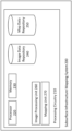
- FIG. 2 illustrates an example block diagram of a subsurface infrastructure mapping system, in accordance with some embodiments of the presently disclosed subject matter.
- Subsurface infrastructure mapping system 200 can include a processing circuitry 210.
- Processing circuitry 210 can include a processor 220 and a memory 230.
- Processor 220 can be a suitable hardware-based electronic device with data processing capabilities, such as, for example, a general purpose processor, digital signal processor (DSP), a specialized Application Specific Integrated Circuit (ASIC), one or more cores in a multicore processor etc.
- DSP digital signal processor
- ASIC Application Specific Integrated Circuit
- Processor 220 can also consist, for example, of multiple processors, multiple ASICs, virtual processors, combinations thereof etc.
- Memory 230 can be, for example, a suitable kind of volatile and/or non-volatile storage, and can include, for example, a single physical memory component or a plurality of physical memory components. Memory 230 can also include virtual memory. Memory 230 can be configured to, for example, store various data used in computation.
- Processing circuitry 210 can be configured to execute several functional modules in accordance with computer-readable instructions implemented on a non-transitory computer-readable storage medium. Such functional modules are referred to hereinafter as comprised in the processing circuitry. These modules can include, for example, image processing unit 260, and mapping unit 270.
- Image processing unit 260 can employ - for example - computer vision techniques (e.g. utilizing machine learning methods such as convolutional neural networks or other suitable method) to perform image analysis on terrain images of various types. In this manner, it can extract surface features (and surface feature geographical location information) from an image.
- computer vision techniques e.g. utilizing machine learning methods such as convolutional neural networks or other suitable method
- Image processing unit 260 can perform image analysis on - for example - images stored in image data repository 240.
- Mapping unit 270 can perform techniques utilizing the extracted surface feature data (e.g. the techniques described hereinbelow with reference to Figs. 3-5E ) to define locations of one or more substructure utility infrastructure (SUI) zones, where each zone contains a particular subsurface utility infrastructure.
- SAI substructure utility infrastructure
- an SUI can be a network of infrastructure components (e.g. pipes, valves, connection points etc.) and that some components can be above-surface while others are subsurface.
- Mapping unit 270 can output generated map data to - for example - map data repository 250.
- the subsurface infrastructure mapping system 200 can be a standalone entity, or integrated, fully or partly, with other entities.
- FIG. 3 illustrates a flow diagram of an example process of generating a digital map including data indicative of a location of a zone that includes a subsurface utility infrastructure, in accordance with some embodiments of the presently disclosed subject matter.
- image data repository 240 can be preloaded with one or images of a terrain to be mapped. It is further noted that map data repository 250 can be preloaded with initial map data.
- Processing circuitry 210 can optionally receive ( 300 ) initial digital map data pertaining to the surface area.
- Initial map data can be previously available data describing subsurface utility infrastructure.
- the initial map data can be of various types such as Geographic Information System (GIS) data, Computer Aided Design (CAD) data, Postgres with geospatial extensions (PostGIS), image data such as Portable Network Graphics (PNG) format, various vector or raster formats etc.
- GIS Geographic Information System
- CAD Computer Aided Design
- PostGIS Postgres with geospatial extensions
- image data such as Portable Network Graphics (PNG) format
- PNG Portable Network Graphics
- vector or raster formats various vector or raster formats etc.
- initial map data that pertains to locations of subsurface utility infrastructure is inexact and/or out of date.
- the initial digital map data can however (in some embodiments) be utilized in conjunction with data derived from terrain image analysis to e.g. reduce the size of regions of uncertainty (herein termed "tolerance" regions) of zones of subsurface utility infrastructure, as described hereinbelow.
- Processing circuitry 210 can next receive ( 310 ) an image of a surface area to be mapped.
- the image can be received, for example, from image data repository 240 or from another source.
- the received image can be associated with particular geographic coordinates that pertain to the perimeter of the image or to one or more particular features of the image.
- the received image can be of various image types.
- images can be optical images e.g. taken by a camera from overhead (e.g. via drone), horizontally (e.g. street view) etc.
- images can be derivative of other types of imaging or other types of sensors e.g. infrared, hyperspectral, multispectral, electro-optic imaging, synthetic aperture radar imaging, remote geophysical sensing; lidar, etc.
- Processing circuitry 210 can next identify ( 320 ) surface features in the image.
- surface feature can be broadly construed as a visible or detectable terrain feature that is informative of the location and/or type of utility infrastructure that lies below the terrain surface.
- Some surface features connect to subsurface utility infrastructure in a manner that indicates the location of the point of connection. Such surface features are herein said to be of the "infrastructure connection point" surface feature type.
- terrain markings indicative of a current or past excavation to install utility infrastructure can be present.
- markings can include e.g. soil phenomena, spectral signature phenomena, vegetation, or other indications that discriminate an excavation area from its surroundings.
- a surface feature is herein said to be of the "excavation footprint” or “excavation evidence” surface feature type.
- regions with characteristics of undisturbed or unexcavated terrain can be present e.g. vegetation, trees, building structures, or undisturbed rock or earth configurations.
- Such a surface feature is herein said to be of the "unexcavated terrain area" surface feature type.
- public works surface markings can be present, as described below with reference to Figs. 6A-6E .
- Such surface features are herein said to be of the "public works surface markings" surface feature type.
- public works surface markings can be of various types, including:
- Processing circuitry 210 can utilize image analysis/computer vision methods as known in the art to identify surface features.
- Processing circuitry 210 can also identify the surface feature type and/or the surface feature orientation (i.e. the direction to which the transformer etc. is oriented).
- Processing circuitry 210 can also identify respective geographic coordinates indicative of the location of the surface feature, using methods as known in the art.
- the surface feature location can be coordinates of a single point on the terrain.
- the surface feature location can be coordinates of a zone.
- processing circuitry 210 can utilize multiple images of a terrain area.
- multi-temporal image sets e.g. a series of historical images
- images from different vantage points e.g. overhead and street view
- images from different types of cameras/sensors can be utilized to provide different surface features.
- Processing circuitry 210 can next calculate ( 330 ) data indicative of a location of utility infrastructure from the identified surface features.
- processing circuitry 210 does this by, for at least one surface feature: a) determining data indicative of a location of a utility infrastructure in accordance with, at least, the surface feature type and the surface feature location.
- processing circuitry 210 (for example: mapping unit 270 ) additionally performs: b) determining a location tolerance in accordance with, at least, the surface feature type - as will be described hereinbelow.
- presence of (for example) a water valve on the terrain surface can be informative of a water transport infrastructure located directly beneath the valve.
- processing circuitry 210 (for example: mapping unit 270 ) can accordingly calculate the location of a point of the water transport infrastructure from the surface feature location.
- processing circuitry 210 can calculate data indicative of the location of (for example) the point of connection to the subsurface utility infrastructure, in accordance with the type of ICP (e.g. water valve etc.), in conjunction with the surface feature location
- ICP infrastructure connection point
- the presence of (for example) a surface water valve on the terrain surface can be informative of the water transport infrastructure being located within a 1-meter radius of the valve (for example: due to technical constraints,or due to utility provider policy).
- the 0-to-1 meter range within which the point of subsurface water transport infrastructure can be located is termed a "utility distance range".
- processing circuitry 210 for example: mapping unit 270
- mapping unit 270 can accordingly estimate the location of a point of the infrastructure in accordance with the location of the surface feature, and - optionally - the utility distance range (for example: by estimating the point to be in the center of the diameter and underneath the valve, or at some other point in the diameter).
- Processing circuitry 210 can also then calculate a location tolerance in accordance with the "utility distance range" (for example: the location tolerance can be 1 meter in any direction). It is noted that when the distance between the surface feature and the point of the infrastructure is known precisely (e.g. from technical constraints or policy of the utility provider), the utility distance range is 0.
- the presence of (for example) a surface water valve on the terrain surface can be informative of the water transport infrastructure being located within 1-meter of the valve - in a particular direction relative to the orientation of the valve (e.g. it may be known that the infrastructure can be located within 1 meter away, at a 90-degree angle to the valve).
- processing circuitry 210 (for example: mapping unit 270 ) can accordingly estimate the location of a point of the water transport infrastructure in accordance with the location of the surface feature, the orientation of the surface feature, the utility distance range (0-to-1 meter), and the infrastructure direction associated with the infrastructure connecting point type.
- processing circuitry 210 can calculate data indicative of the location of the zone of the subsurface utility infrastructure in accordance with the surface feature location zone (e.g. the zone of the subsurface utility infrastructure can be identical to the surface feature location zone).
- processing circuitry 210 can calculate data indicative of the location the zone of the subsurface utility infrastructure in accordance with the surface feature location zone (e.g. the zone of the subsurface utility infrastructure can be identical to the surface feature location zone).
- processing circuitry 210 can calculate data indicative of the location of the point, zone, or absence zone of the subsurface utility infrastructure in accordance with the specific type of public works surface marking e.g.
- Processing circuitry 210 can next define ( 340 ) a zone including a subsurface utility infrastructure - by utilizing the calculated utility location data (and optionally utilizing initial map data). An example method of defining such a zone is described hereinbelow, with reference to Fig. 4 .
- FIG. 4 illustrates a flow diagram of an example method of defining a location of a zone including the SUI in accordance with the calculated utility locations, in accordance with some embodiments of the presently disclosed subject matter.
- Processing circuitry 220 can utilize the IULs (caculcated from the surface features) to define coordinates of a zone including the SUI.
- the zone can then be utilized - for example - to avoid damage to the SUI during excavation operations.
- Such a zone is herein termed an "approximated utility zone".
- processing circuitry 210 can - for each SUI point define ( 400 ) a zone connecting the point to (for example) its two closest neighbors.
- processing circuitry 210 can define these zones so as to incorporate uncertainty about the actual path of the utility line between the identified SUI points.
- processing circuitry 210 can define these zones so as to incorporate uncertainty about the precise location of the SUI points that result from location tolerance.
- Processing circuitry 220 (for example: mapping unit 270 ) can add ( 420 ) the zones of SUI indicated by excavation footprint surface features.
- processing circuitry 220 can adjust ( 430 ) the defined zone in accordance with initial map data. For example: if the utility locations indicated by initial map data are highly consistent with calculated utility locations, then processing circuitry 220 (for example: mapping unit 270 ) can reduce the tolerance included in the zone definitions.
- processing circuitry 220 can adjust ( 440 ) the defined zone in accordance with SUI-free zones as indicated by unexcavated area surface features.
- FIGs. 5A-5E illustrate an example overhead image of a terrain area with successive steps to define a zone including a subsurface utility infrastructure, on the basis of surface features indicative of locations of the subsurface utility infrastructure, in accordance with some embodiments of the presently disclosed subject matter.
- Fig. 5A illustrates an example overhead image of a terrain area, together with example surface features.
- Excavation footprint 510 can be an area where previous excavation is discernable (for example a ditch, or earth which has been placed to fill a ditch).
- Processing circuitry 210 e.g. image processing unit 260
- processing circuitry 210 e.g. image processing unit 260
- surface features 510A 510B 510C can be - for example - electrical transformers, which are connected to subsurface electrical infrastructure at points 520A 520B 520C respectively. It is noted that points 520A 520B 520C are - for example - not visible in the overhead image. Each point 520A 520B 520C is - in the current example - a fixed distance and orientation from the respective transformers 510A 510B 510C (for example: because of the policy or technical constraints of the utility provider).
- Processing circuitry 210 e.g. image processing unit 260 and mapping unit 270 ) can identify transformers 510A 510B 510C in the overhead image, and infer the locations of 520A 520B 520C.
- unexcavated terrain 440 can be a tree area.
- Processing circuitry 210 e.g. image processing unit 260
- Processing circuitry 210 e.g. mapping unit 270
- Fig. 5B illustrates an example first step of defining a zone including the subsurface utility infrastructure.
- Processing circuitry 210 e.g. mapping unit 270
- Fig. 5C illustrates example tolerance zones resulting from uncertainty of the subsurface path of the electrical supply cable which connects the inferred locations of points of the SUI.
- Processing circuitry 210 e.g. mapping unit 270
- these zones in accordance with known policies and/or known technical constraints affecting installation of the utility.
- Processing circuitry 210 e.g. mapping unit 270
- Fig. 5D illustrates an example next step of the processing circuitry 210 (e.g. mapping unit 270 ) extending the defined zone in accordance with the excavation footprint (for example: edges of the zone can be identical with the excavation footprint).
- the processing circuitry 210 e.g. mapping unit 270
- Fig. 5E illustrates an example additional step of defining the zone of the subsurface utility infrastructure in accordance with the location of the tree area.
- processing circuitry 210 e.g. mapping unit 270
- mapping unit 270 can reduce the extent of tolerance in the zone so that there is no overlap with unexcavated terrain 440 (as will be described in more detail below with reference to Fig. 5 ).
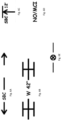
- Figs. 6A-6E illustrate non-limiting examples of public works surface markings (PWSMs), in accordance with some embodiments of the presently disclosed subject matter.
- PWSMs public works surface markings
- Public works surface markings can be markings that were placed on public infrastructure to indicate placement of utilities.
- utility construction crews place PWSMs on surfaces after installing underground utility infrastructure.
- surveyors place PWSMs subsequent to utility installation.
- PWSMs consist of painted text and/or symbols on surfaces such as roads or sidewalk. In some examples PWSMs consist of flags (possibly including text and/or symbols) placed on open terrain.
- the color of the marking can indicate the type of utility (e.g. red for utility type of electric power lines, blue for utility type of potable water etc.) associated with a PWSM.
- a marking can include text or images or other data that is indicative of supplementary data associated with a PWSM (such as the owner, operator, other identifier etc. of the utility; diameter, depth etc. of the utility line; other supplementary data).
- processing circuitry 210 identifies PWSMs in images. Such identified PWSMs can constitute surface features. Processing circuitry 210 (for example: mapping unit 270 ) can then calculate data indicative of locations of utility infrastructure from the PWSM surface features.
- Fig. 6A illustrates an example of a PWSM that is a utility location linear road marking.
- the line illustrated in Fig. 6A can denote that utility infrastructure is located directly beneath the line on the road.
- the line is non-contiguous, and includes text (" SBC") indicative of the owner of the utility.
- SBC text indicative of the owner of the utility.
- a utility location linear road marking need not be strictly linear, and can have gaps, curves, elbows etc.
- a utility location linear road marking can be associated with e.g. a utility line diameter, or a utility line location tolerance.
- the utility line diameter or utility line location tolerance can appear in the PWSM.
- the utility line diameter or a utility line location tolerance can be assumed or preknown.
- Fig. 6B illustrates another example of a PWSM that is a utility location linear road marking.
- a different style of line marking is used.
- the line illustrated in Fig. 6B can denote that utility infrastructure is located directly beneath the line.
- the diameter (42") appears in the PWSM - indicated by the preceding "W".
- Fig. 6C illustrates an example PWSM that is a displaced utility point indicator road marking.
- the road marking includes an arrow and text indicating the displacement direction and displacement distance to indicate where the utility is in fact located.
- This example additionally includes text ("SBC") indicating the owner of the utility.
- SBC text
- the utility line diameter or utility line location tolerance can appear in the PWSM. In some other embodiments, the utility line diameter or a utility line location tolerance can be assumed or preknown.
- Fig. 6D illustrates an example PWSM that is a utility absence zone road marking.
- the road marking includes text (the word "NO") indicating that no utility is present.
- This example additionally includes text ("SBC") indicating the owner of the utility.
- a utility absence road marking indicates absence of a utility within a certain explicit or implicit radius, within a certain explicit or implicit rectangular zone, or within a zone delimited by some other method (such as edges of a road intersection).
- a utility absence zone location tolerance can be assumed or preknown, or can appear in the PWSM.
- Fig. 6E illustrates an example PWSM that is a utility point road marking.
- the road marking illustrated in Fig. 6A can denote that utility infrastructure is located directly beneath the center of the symbol.
- a utility line diameter or utility point location tolerance can appear in the PWSM.
- the utility point diameter or a utility point location tolerance can be assumed or preknown.
- a PWSM that is a utility point marking flag (not shown) can be utilized.
- a utility point marking flag can denote that utility infrastructure is located directly beneath the flag.
- a utility line diameter or utility point location tolerance (or other data) can appear on the flag.
- the utility point diameter or a utility point location tolerance can be assumed or preknown.
- system according to the invention may be, at least partly, implemented on a suitably programmed computer.
- the invention contemplates a computer program being readable by a computer for executing the method of the invention.
- the invention further contemplates a non-transitory computer-readable memory tangibly embodying a program of instructions executable by the computer for executing the method of the invention.
Landscapes
- Engineering & Computer Science (AREA)
- Theoretical Computer Science (AREA)
- General Engineering & Computer Science (AREA)
- General Physics & Mathematics (AREA)
- Databases & Information Systems (AREA)
- Physics & Mathematics (AREA)
- Structural Engineering (AREA)
- Civil Engineering (AREA)
- Mining & Mineral Resources (AREA)
- Multimedia (AREA)
- Data Mining & Analysis (AREA)
- Computer Vision & Pattern Recognition (AREA)
- Remote Sensing (AREA)
- Library & Information Science (AREA)
- Artificial Intelligence (AREA)
- Geophysics And Detection Of Objects (AREA)
Priority Applications (2)
| Application Number | Priority Date | Filing Date | Title |
|---|---|---|---|
| EP22150534.0A EP4210001A1 (de) | 2022-01-07 | 2022-01-07 | Digitale fernabbildung einer unterirdischen versorgungsinfrastruktur |
| US18/150,592 US12540830B2 (en) | 2020-07-09 | 2023-01-05 | Digital remote mapping of subsurface utility infrastructure |
Applications Claiming Priority (1)
| Application Number | Priority Date | Filing Date | Title |
|---|---|---|---|
| EP22150534.0A EP4210001A1 (de) | 2022-01-07 | 2022-01-07 | Digitale fernabbildung einer unterirdischen versorgungsinfrastruktur |
Publications (1)
| Publication Number | Publication Date |
|---|---|
| EP4210001A1 true EP4210001A1 (de) | 2023-07-12 |
Family
ID=79730489
Family Applications (1)
| Application Number | Title | Priority Date | Filing Date |
|---|---|---|---|
| EP22150534.0A Withdrawn EP4210001A1 (de) | 2020-07-09 | 2022-01-07 | Digitale fernabbildung einer unterirdischen versorgungsinfrastruktur |
Country Status (1)
| Country | Link |
|---|---|
| EP (1) | EP4210001A1 (de) |
Citations (1)
| Publication number | Priority date | Publication date | Assignee | Title |
|---|---|---|---|---|
| EP3748583A1 (de) * | 2019-06-04 | 2020-12-09 | My Virtual Reality Software AS | Visualisierung einer unterirdischen versorgungsleitung |
-
2022
- 2022-01-07 EP EP22150534.0A patent/EP4210001A1/de not_active Withdrawn
Patent Citations (1)
| Publication number | Priority date | Publication date | Assignee | Title |
|---|---|---|---|---|
| EP3748583A1 (de) * | 2019-06-04 | 2020-12-09 | My Virtual Reality Software AS | Visualisierung einer unterirdischen versorgungsleitung |
Non-Patent Citations (2)
| Title |
|---|
| BILAL MUHAMMAD ET AL: "Inferring the most probable maps of underground utilities using Bayesian mapping model", JOURNAL OF APPLIED GEOPHYSICS, vol. NO150, 1 March 2018 (2018-03-01), NL, pages 52 - 66, XP055934448, ISSN: 0926-9851, DOI: 10.1016/j.jappgeo.2018.01.006 * |
| TANOLI WAQAS ARSHAD ET AL: "Damage Prevention for underground utilities using machine guidance", AUTOMATION IN CONSTRUCTION, ELSEVIER, AMSTERDAM, NL, vol. 107, 9 August 2019 (2019-08-09), XP085856681, ISSN: 0926-5805, [retrieved on 20190809], DOI: 10.1016/J.AUTCON.2019.102893 * |
Similar Documents
| Publication | Publication Date | Title |
|---|---|---|
| US9183646B2 (en) | Apparatus, systems and methods to generate electronic records of underground facility marking operations performed with GPS-enabled marking devices | |
| WO2016198873A1 (en) | Flood risk mapping and warning system and method | |
| EP3798993A1 (de) | Designentwicklungswerkzeuge zur visualisierung von bestehenden versorgungsleitungen in einem landgebiet und zur validierung der platzierung neuer versorgungsleitungen | |
| CN110108257B (zh) | 一种基于无人机航拍影像和静态规划图相匹配的展示方法 | |
| US11709870B2 (en) | Comprehensive utility line database and user interface for excavation sites | |
| Lin et al. | Leveraging optical and SAR data with a UU-Net for large-scale road extraction | |
| CN114067245A (zh) | 一种铁路外部环境隐患识别方法及系统 | |
| US20150377615A1 (en) | Method of documenting a position of an underground utility | |
| Yan et al. | The LADM-based 3D underground utility mapping: Case study in Singapore | |
| McNeil et al. | The truth about drones in mapping and surveying | |
| US12540830B2 (en) | Digital remote mapping of subsurface utility infrastructure | |
| Alshaiba et al. | Automatic manhole extraction from MMS data to update basemaps | |
| CA3146945A1 (en) | Digital remote mapping of subsurface utility infrastructure | |
| CN104123310A (zh) | 基于卫星图像的路网信息的处理方法及装置 | |
| EP4210001A1 (de) | Digitale fernabbildung einer unterirdischen versorgungsinfrastruktur | |
| CN117218524A (zh) | 一种基于空天地多视角影像协同的城市违章区域识别方法 | |
| Ganendra et al. | The role of airborne LiDAR survey technology in digital transformation | |
| Brigante et al. | USE OF MULTISPECTRAL SENSORS WITH HIGH SPATIAL RESOLUTION FOR TERRITORIAL AND ENVIRONMENTAL ANALYSIS. | |
| Puripanda et al. | Best practice of utilizing drones for surveying and mapping in the Bahrain oil field | |
| Mothi Kumar et al. | GIS based cadastral level forest information system using World View-II data in Bir Hisar (Haryana) | |
| Hu | 3D Reconstruction of Exposed Underground Utilities Using Photogrammetric Methods | |
| WO2025252297A1 (en) | Utility infrastructure mapping | |
| Mori et al. | Study on the Applicability of UAV Surveying for On-Site Beach Monitoring | |
| Pichaikutty | Detection of curbside storm drain from street level images using Faster R-CNN | |
| Liu et al. | UAV-based supervision methodology for water diversion projects with monitoring points serving as image control points-taking the Jiaodong Yellow River water diversion project as an example |
Legal Events
| Date | Code | Title | Description |
|---|---|---|---|
| PUAI | Public reference made under article 153(3) epc to a published international application that has entered the european phase |
Free format text: ORIGINAL CODE: 0009012 |
|
| STAA | Information on the status of an ep patent application or granted ep patent |
Free format text: STATUS: THE APPLICATION HAS BEEN PUBLISHED |
|
| AK | Designated contracting states |
Kind code of ref document: A1 Designated state(s): AL AT BE BG CH CY CZ DE DK EE ES FI FR GB GR HR HU IE IS IT LI LT LU LV MC MK MT NL NO PL PT RO RS SE SI SK SM TR |
|
| STAA | Information on the status of an ep patent application or granted ep patent |
Free format text: STATUS: THE APPLICATION IS DEEMED TO BE WITHDRAWN |
|
| 18D | Application deemed to be withdrawn |
Effective date: 20240113 |