EP4210082B1 - Schalteinheit und schaltvorrichtung - Google Patents
Schalteinheit und schaltvorrichtung Download PDFInfo
- Publication number
- EP4210082B1 EP4210082B1 EP21874203.9A EP21874203A EP4210082B1 EP 4210082 B1 EP4210082 B1 EP 4210082B1 EP 21874203 A EP21874203 A EP 21874203A EP 4210082 B1 EP4210082 B1 EP 4210082B1
- Authority
- EP
- European Patent Office
- Prior art keywords
- stationary contact
- pin
- housing
- switch unit
- arc
- Prior art date
- Legal status (The legal status is an assumption and is not a legal conclusion. Google has not performed a legal analysis and makes no representation as to the accuracy of the status listed.)
- Active
Links
Images



Classifications
-
- H—ELECTRICITY
- H01—ELECTRIC ELEMENTS
- H01H—ELECTRIC SWITCHES; RELAYS; SELECTORS; EMERGENCY PROTECTIVE DEVICES
- H01H1/00—Contacts
- H01H1/58—Electric connections to or between contacts; Terminals
-
- H—ELECTRICITY
- H01—ELECTRIC ELEMENTS
- H01H—ELECTRIC SWITCHES; RELAYS; SELECTORS; EMERGENCY PROTECTIVE DEVICES
- H01H19/00—Switches operated by an operating part which is rotatable about a longitudinal axis thereof and which is acted upon directly by a solid body external to the switch, e.g. by a hand
- H01H19/64—Encased switches adapted for ganged operation when assembled in a line with identical switches, e.g. stacked switches
-
- H—ELECTRICITY
- H01—ELECTRIC ELEMENTS
- H01H—ELECTRIC SWITCHES; RELAYS; SELECTORS; EMERGENCY PROTECTIVE DEVICES
- H01H33/00—High-tension or heavy-current switches with arc-extinguishing or arc-preventing means
- H01H33/02—Details
- H01H33/04—Means for extinguishing or preventing arc between current-carrying parts
- H01H33/18—Means for extinguishing or preventing arc between current-carrying parts using blow-out magnet
- H01H33/182—Means for extinguishing or preventing arc between current-carrying parts using blow-out magnet using permanent magnets
-
- H—ELECTRICITY
- H01—ELECTRIC ELEMENTS
- H01H—ELECTRIC SWITCHES; RELAYS; SELECTORS; EMERGENCY PROTECTIVE DEVICES
- H01H1/00—Contacts
- H01H1/58—Electric connections to or between contacts; Terminals
- H01H1/5805—Connections to printed circuits
-
- H—ELECTRICITY
- H01—ELECTRIC ELEMENTS
- H01H—ELECTRIC SWITCHES; RELAYS; SELECTORS; EMERGENCY PROTECTIVE DEVICES
- H01H33/00—High-tension or heavy-current switches with arc-extinguishing or arc-preventing means
- H01H33/02—Details
- H01H33/53—Cases; Reservoirs, tanks, piping or valves, for arc-extinguishing fluid; Accessories therefor, e.g. safety arrangements, pressure relief devices
-
- H—ELECTRICITY
- H01—ELECTRIC ELEMENTS
- H01H—ELECTRIC SWITCHES; RELAYS; SELECTORS; EMERGENCY PROTECTIVE DEVICES
- H01H1/00—Contacts
- H01H1/12—Contacts characterised by the manner in which co-operating contacts engage
- H01H1/36—Contacts characterised by the manner in which co-operating contacts engage by sliding
- H01H1/365—Bridging contacts
-
- H—ELECTRICITY
- H01—ELECTRIC ELEMENTS
- H01H—ELECTRIC SWITCHES; RELAYS; SELECTORS; EMERGENCY PROTECTIVE DEVICES
- H01H19/00—Switches operated by an operating part which is rotatable about a longitudinal axis thereof and which is acted upon directly by a solid body external to the switch, e.g. by a hand
- H01H19/02—Details
- H01H19/08—Bases; Stationary contacts mounted thereon
-
- H—ELECTRICITY
- H01—ELECTRIC ELEMENTS
- H01H—ELECTRIC SWITCHES; RELAYS; SELECTORS; EMERGENCY PROTECTIVE DEVICES
- H01H9/00—Details of switching devices, not covered by groups H01H1/00 - H01H7/00
- H01H9/30—Means for extinguishing or preventing arc between current-carrying parts
- H01H9/34—Stationary parts for restricting or subdividing the arc, e.g. barrier plate
- H01H9/342—Venting arrangements for arc chutes
Definitions
- the present application relates to the field of electrical switching technologies, and in particular, to a switch unit and a switching device.
- a switching device performs two functions in a power system: 1. a control function: putting some power devices or lines into operation or stopping them from operating according to an operating requirement of the power system; 2. a protection function: when a power device or line fails, quickly removing a failed part from the power system, to ensure normal operating of a failure-free part of the power system.
- a switching device is usually connected to a power system through a mechanical connection.
- a wire entry/exit terminal is connected to an external wire or copper bar by using a screw.
- Document CN 211 294 934 U describes a fixed contact with an integrated structure for a cam switch, and the fixed contact comprises a contact part, a connecting part and a welding needle which are integrally formed.
- Document EP 3 104 386 B1 describes a cam rotary switch with double positive break contacts solderable on an electronic board.
- Document US 2014/097155 A1 describes a rotation mechanism for a rotary switch and a method of operating the rotary switch.
- Document CN 208 014 602 U describes a rotation type isolating switch contact module.
- Document US 2016/104591 A1 describes a single-pole breaking unit comprising a rotary contact bridge, a switchgear device, and a circuit breaker comprising such a unit.
- Document CN 109 637 871 A describes a miniature direct current switch including an insulating shell.
- An objective of the present invention is to provide a switch unit and a switching device, to reduce a quantity of contact connections, simplify a connection manner, and improve safety during use.
- Embodiments of the present invention are implemented as follows.
- a switch unit including at least one stationary contact assembly.
- Each stationary contact assembly includes a first stationary contact, a second stationary contact, and a first pin connected to the first stationary contact.
- the first pin is soldered to a circuit board.
- the stationary contact assembly further includes a connector, one terminal of the connector is connected to the second stationary contact, and the other terminal is connected to the circuit board.
- a wiring terminal is disposed on the first stationary contact and/or the second stationary contact, and when the wiring terminal is used for connecting a wire, the wire extends in a preset direction.
- the switch unit further includes an auxiliary pin, one terminal of the auxiliary pin is connected to the first stationary contact or the second stationary contact, and the other terminal is soldered to the circuit board.
- a first protrusion is disposed on the first stationary contact, the first protrusion is located on one side of the first stationary contact and faces a side on which an electric arc is produced, a second protrusion is disposed on the second stationary contact, and the second protrusion is located on one side of the second stationary contact and faces a side on which an electric arc is produced.
- the switch unit further includes a housing
- the first pin includes a first bending portion connected to the first stationary contact and a first extending portion connected to the first bending portion, the first extending portion and the first stationary contact are located on different planes, the first pin is away from an arc discharge opening of the housing
- the second pin includes a second bending portion connected to the second stationary contact and a second extending portion connected to the second bending portion, the second extending portion and the second stationary contact are located on different planes, and the second pin is away from the arc discharge opening.
- the switch unit further includes a housing and a permanent magnet disposed in the housing, an arc extinguishing area is formed when a movable contact is disconnected from the first stationary contact or the second stationary contact, the permanent magnet corresponds to the arc extinguishing area, and an included angle between a straight line on which a magnetic blowout force applied by the permanent magnet to an electric arc in the arc extinguishing area is located and an orthographic projection of the straight line on a motion plane of the movable contact is greater than or equal to 45 degrees and less than or equal to 135 degrees.
- a limiting portion is disposed on the housing, and is configured to limit a position of the first pin and/or the second pin.
- the limiting portion includes a limiting groove and a clamping protrusion, the limiting groove and the clamping protrusion are separately located on two sides of the housing in a stacking direction, the first pin and/or the second pin pass through the limiting groove, and when housings are stacked, a limiting groove and a clamping protrusion on adjacent housings are clamped, to limit the position of the first pin and/or the second pin; or the limiting portion is a limiting via, and the first pin and/or the second pin pass through the limiting via.
- an arc discharge opening is provided on the housing, an arcing space connected to the arc discharge opening is correspondingly provided in the housing, a boss is further disposed in the housing, and the boss is located in the arcing space, so that the arcing space forms a channel whose size gradually decreases and then increases.
- first extending portion and the second extending portion separately extend out from sides of the housing, and the first extending portion and the second extending portion are separately located on adjacent sides of the housing or opposite sides of the housing.
- a switching device including the switch unit according to any one of the foregoing implementations, where switch units are stacked by using housings.
- the switching device further includes an arc partition board, the arc partition board includes a plurality of isolation chambers, and the isolation chambers are in a one-to-one correspondence with first pins and/or second pins of the switch units, to block charged particles.
- the arc partition board and the housing are integrally molded, or the arc partition board and the housing are separately disposed.
- a first stationary contact and a second stationary contact are diagonally arranged in the switch unit, and stationary contact assemblies in adjacent switch units are arranged in a staggered manner.
- a baffle plate and a fastener connected to a stationary contact assembly are disposed on one side of the housing, and the fastener is located between two baffle plates of adjacent housings.
- each stationary contact assembly includes a first stationary contact, a second stationary contact, and a first pin connected to the first stationary contact.
- the switching device When the switching device is connected to a circuit board, the switching device is directly connected to the circuit board through the first pin, without using a binding post, thereby reducing a quantity of accidents caused by poor electrical contact.
- An appropriate connection manner is used for the second stationary contact according to an actual requirement, to adapt to a space limitation and improve flexibility of wiring. In the foregoing manner, a quantity of manual contacts in a conventional connection manner can be reduced, a quantity of contact connections can be reduced, a connection manner can be simplified, and safety during use can be improved.
- connection may be a fixed connection, a detachable connection, or an integrated connection; may be a mechanical connection or an electrical connection; or may be a direct connection, an indirect connection through an intermediate medium, or an internal connection between two components.
- an embodiment of this invention provides a switch unit 100, used in a switching device, for example, a rotary switch, an isolation switch, or a circuit breaker.
- the switch unit 100 includes at least one stationary contact assembly 110.
- Each stationary contact assembly 110 includes a first stationary contact 112, a second stationary contact 116, and a first pin 114 connected to the first stationary contact 112.
- the first pin 114 is soldered to a circuit board 105.
- the stationary contact assembly 110 includes the first stationary contact 112 and the first pin 114 electrically connected to the first stationary contact 112, where the first stationary contact 112 is connected to a movable contact, and the first pin 114 is soldered to the circuit board 105 to form a connection path.
- the first stationary contact 112 and the first pin 114 are integrally molded, and a required electrical connection relationship may be formed for the second stationary contact 116 through wiring. In the foregoing manner, wiring and installation manners for transmission are changed. This helps improve stability of wiring, avoid excessive manual contacts, improve stability of a connection, and improve connection efficiency.
- the first pin 114 may be soldered to the circuit board 105 through wave soldering.
- a soldering device may be used to perform automatic soldering. This is suitable for mass production, and helps reduce labor costs and improve connection efficiency.
- an electronic component inserted the circuit board 105, the switching device 200, and the circuit board 105 may form a whole. This helps reduce a quantity of contacts (that is, points for wiring) in subsequent use and simplify a connection manner.
- the switch unit 100 has movable contacts for respectively connecting to the first stationary contact 112 and the second stationary contact 116, so that a connection path is formed when the movable contacts are respectively connected to the first stationary contact 112 and the second stationary contact 116.
- the movable contacts may perform a required spatial action based on a contact support, to implement a required switching-off or switching-on operation.
- each stationary contact assembly 110 includes a first stationary contact 112, a second stationary contact 116, and a first pin 114 connected to the first stationary contact 112.
- the switching device When the switching device is connected to the circuit board 105, the switching device may be directly connected to the circuit board 105 through the first pin 114, without using a binding post, thereby reducing a quantity of accidents caused by poor electrical contact.
- An appropriate connection manner may be used for the second stationary contact 116 according to an actual requirement, to adapt to a space limitation and improve flexibility of wiring. In the foregoing manner, a quantity of manual contacts in a conventional connection manner can be reduced, a quantity of contact connections can be reduced, a connection manner can be simplified, and safety during use can be improved.
- the stationary contact assembly 110 further includes a second pin 118 connected to the second stationary contact 116.
- the first stationary contact 112 and the first pin 114 are integrally molded.
- the second stationary contact 116 and the second pin 118 are integrally molded.
- the second pin 118 is soldered to the circuit board 105.
- the first stationary contact 112 and the first pin 114 are integrally molded, and the second stationary contact 116 and the second pin 118 are also integrally molded.
- the switch unit 100 is soldered to the circuit board 105 through the first pin 114 and the second pin 118. This facilitates integrated disposing of a product, and helps reduce workload of a user during wiring.
- the stationary contact assembly 110 further includes a connector 130.
- One terminal of the connector 130 is connected to the second stationary contact 116, and the other terminal is connected to the circuit board 105.
- the connector 130 may be a flexible connector or a rigid connector.
- a flexible connector for example, a copper wire
- the switch unit 100 needs to be electrically connected to a circuit board 105
- the electrical connection can be better performed, avoiding difficulty in fitting due to a deviation of a hole position. This helps improve operability of an actual operation.
- a rigid connector for example, a copper plate
- specific support may be provided during connection, preventing excessive flexibility from affecting a wiring speed. This further facilitates connection and fastening.
- a wiring terminal 140 is disposed on the first stationary contact 112 and/or the second stationary contact 116.
- the wiring terminal 140 is used for connecting a wire 107, the wire 107 extends in a preset direction.
- the switch unit 100 when the switch unit 100 is connected to the circuit board 105, and when the switch unit 100 is connected to the circuit board 105 through the first wiring pin 114 or the second wiring pin 118, soldering may not be suitable for wiring due to impact of an installation environment.
- the wire 107 may be connected to the wiring terminal 140, and the wire 107 is led to a side of the switching device on which an operation can be performed more easily. This helps improve applicability during use.
- the switch unit 100 further includes an auxiliary pin 150.
- One terminal of the auxiliary pin 150 is connected to the first stationary contact 112 or the second stationary contact 116, and the other terminal is soldered to the circuit board 105.
- the auxiliary pin 150 is disposed on the first stationary contact 112 or the second stationary contact 116.
- the auxiliary pin 150 is soldered to the circuit board 105, to implement grounding through the auxiliary pin 150. When a lightning strike occurs, a current is led to the ground. This can protect the switch unit 100, and helps improve stability of the product during use.
- a first protrusion 1122 is disposed on the first stationary contact 112, the first protrusion 1122 is located on one side of the first stationary contact 112 and faces a side on which an electric arc is produced, a second protrusion 1262 is disposed on the second stationary contact 116, and the second protrusion 1262 is located on one side of the second stationary contact 116 and faces a side on which an electric arc is produced.
- the first protrusion 1122 and the second protrusion 1262 mainly use a characteristic of arcing at a conductor tip.
- a produced electric arc runs on the first stationary contact 112 or the second stationary contact 116, thereby preventing the electric arc from splashing and affecting normal and stable use of the switching device 200.
- the switch unit 100 further includes a housing 160.
- the first pin 114 includes a first bending portion 1142 connected to the first stationary contact 112 and a first extending portion 1144 connected to the first bending portion 1142.
- the first extending portion 1144 and the first stationary contact 112 are located on different planes, and the first pin 114 is away from an arc discharge opening 162 of the housing 160.
- the second pin 118 includes a second bending portion 1182 connected to the second stationary contact 116 and a second extending portion 1184 connected to the second bending portion 1182.
- the second extending portion 1184 and the second stationary contact 116 are located on different planes, and the second pin 118 is away from the arc discharge opening 162.
- the first pin 114 can be better attached to the housing 160, and stability of the connection is improved.
- the first pin 114 avoids the arc discharge opening 162.
- the first pin 114 is disposed away from the arc discharge opening 162, so that when charged particles are produced between the movable contact 170 and the stationary contact, the charged particles are prevented from splashing onto the first pin 114 through the arc discharge opening 162 and causing a short circuit of the stationary contact assembly 110. This helps improve stability of an electrical connection.
- the second pin 118 includes the second bending portion 1182, so that the second pin 118 is better attached to the housing 160, and stability of the connection is improved.
- the second pin 118 avoids the arc discharge opening 162.
- the second pin 118 is disposed away from the arc discharge opening 162, so that when charged particles are produced between the movable contact 170 and the stationary contact, the charged particles are prevented from splashing onto the second pin 118 through the arc discharge opening 162 and causing a short circuit of the connector 130. This helps improve stability of an electrical connection.
- the second stationary contact 116 is connected to the circuit board 105 by using the connector 130, the connector 130 may also be disposed away from the arc discharge opening 162, to ensure stability of the connection.
- the switch unit 100 further includes a housing 160 and a permanent magnet 164 disposed in the housing 160.
- An arc extinguishing area is formed when the movable contact 170 is disconnected from the first stationary contact 112 or the second stationary contact 116, and the permanent magnet 164 corresponds to the arc extinguishing area.
- an included angle between a straight line 1642 on which a magnetic blowout force applied by the permanent magnet 164 to an electric arc in the arc extinguishing area is located and an orthographic projection of the straight line on a motion plane 172 of the movable contact 170 is greater than or equal to 45 degrees and less than or equal to 135 degrees.
- the magnetic blowout force applied to the electric arc also deflects at a specific angle
- the straight line on which the magnetic blowout force is located also correspondingly deflects at the same angle. Therefore, as a deflection direction or the position of the permanent magnet 164 changes, the included angle ⁇ between the straight line 1642 on which the magnetic blowout force is located and the orthographic projection of the straight line on the motion plane 172 may correspondingly deflect from 45 degrees to 135 degrees.
- the included angle may be set to 90 degrees, 60 degrees, 80 degrees, 100 degrees, or 128 degrees. When the angle is not 90 degrees, a thickness of the switch unit 100 can be further reduced. This helps improve space utilization.
- the electric arc extends along a direction of the magnetic blowout force.
- the included angle between the straight line 1642 on which the magnetic blowout force applied to the electric arc is located and the orthographic projection of the straight line on the motion plane 172 of the movable contact 170 is greater than or equal to 45 degrees and less than or equal to 135 degrees, an arc extending space is larger. This helps increase an arc extinguishing speed. This can also avoid blocking by another component in the housing 160, thereby helping improve an arc extinguishing effect.
- an arc discharge opening 162 is provided on the housing 160, and an arcing space 163 connected to the arc discharge opening 162 is correspondingly provided in the housing 160.
- a boss 165 is further disposed in the housing 160, and the boss 165 is located in the arcing space 163, so that the arcing space 163 forms a channel whose size gradually decreases and then increases.
- the arcing space 163 forms a channel whose size gradually decreases and then increases.
- an arc speed changes with a change of a cross section (as indicated by an arrow direction in FIG. 7 ).
- a cross section of a front part of a narrow area gradually becomes smaller, and a flow rate gradually increases.
- an arc flow rate exceeds a sound speed.
- an opening gradually becomes larger, a transonic fluid no longer conforms to a rule that a flow rate at a smaller cross section is higher and a flow rate at a larger cross section is smaller.
- a limiting portion is disposed on the housing 160, and is configured to limit the first pin 114 and/or the second pin 118.
- positions of the first pin 114 and the second pin 118 may be limited by using the limiting portion on the housing 160.
- the second stationary contact 116 is connected in another manner, for example, the second stationary contact 116 is connected by using the connector 130, only the position of the first pin 114 may be limited. It may be understood that, alternatively, only the position of the second pin 118 may be limited based on an actual situation during actual use. It may be understood that a position of the auxiliary pin 150 may also be limited by using the limiting portion, to improve stability during connection.
- the limiting portion includes a limiting groove 166 and a clamping protrusion 168.
- the limiting groove 166 and the clamping protrusion 168 are separately located on two sides of the housing 160 in a stacking direction.
- the first pin 114 and/or the second pin 118 pass through the limiting groove 166.
- a limiting groove 166 and a clamping protrusion 168 on adjacent housings 160 are clamped, to limit the first pin 114 and/or the second pin 118.
- the limiting portion is a limiting via 161, and the first pin 114 and/or the second pin 118 pass through the limiting via.
- the first pin 114 and the second pin 118 may separately pass through the limiting groove 166, to limit the first pin 114 and the second pin 118 by using the limiting groove 166.
- the limiting groove 166 and the clamping protrusion 168 are clamped, to press against the first pin 114 and the second pin 118, and prevent the first pin 114 and the second pin 118 from shaking.
- the first pin 114 and/or the second pin 118 may pass through the limiting via 161, to limit the first pin 114 and/or the second pin 118 by using the limiting via 161.
- first pin 114 or the second pin 118 may be fastened, or all pins may be fastened in the foregoing manner.
- the foregoing manner is also applicable to the auxiliary pin 150.
- the first extending portion 1144 and the second extending portion 1184 separately extend from sides of the housing 160, and the first extending portion 1144 and the second extending portion 1184 are separately located on adjacent sides of the housing 160 or opposite sides of the housing 160.
- the first extending portion 1144 and the second extending portion 1184 need to separately extend out from sides of the housing 160.
- the first extending portion 1144 and the second extending portion 1184 may separately extend out from adjacent sides of the housing 160 or opposite sides of the housing 160, to ensure a required connection.
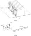
- an embodiment of this application further provides a switching device 200, including the switch unit 100 in the foregoing embodiment.
- Switch units 100 are stacked by using housings 160.
- a quantity of stacking layers of switch units 100 is not specifically limited, and switch units 100 may be flexibly disposed according to an actual requirement. For example, 8, 10, or 12 switch units 100 may be disposed. Specifically, switch units 100 may be properly disposed based on a situation of a line to which the switch units are connected. As shown in FIG. 12 , when a plurality of switch units 100 are stacked, an operation shaft may be connected to a movable contact in each switch unit 100, to control a change of a spatial position of the movable contact, so as to control the switching device 200 to be switched on or switched off.
- a quantity of manual contacts in a conventional connection manner can be reduced, a quantity of contact connections can be reduced, a connection manner can be simplified, and safety during use can be improved.
- the switching device 200 further includes an arc partition board 210.
- the arc partition board 210 includes a plurality of isolation chambers 212.
- the isolation chambers 212 are in a one-to-one correspondence with first pins 114 and/or second pins 118 of the switch units 100, to block charged particles.
- a plurality of separators spaced apart are disposed on the arc partition board 210, and an isolation chamber 212 is formed between adjacent separators.
- an isolation chamber 212 is formed between adjacent separators.
- the arc partition board 210 and the housing 160 are integrally molded, or the arc partition board 210 and the housing 160 are separately disposed. In this way, flexible disposing may be performed according to an actual requirement during specific use. When an operation space is small, integral molding may be performed. When an operation space is abundant, separate disposing may be performed.
- the isolation chambers 212 can better fit the first pins 114 or the second pins 118 when a connection position or a connection manner of the first pins 114 or the second pins 118 changes.
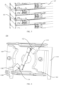
- a first stationary contact 112 and a second stationary contact 116 are diagonally arranged in the switch unit 100, and stationary contact assemblies 110 in adjacent switch units 100 are arranged in a staggered manner.
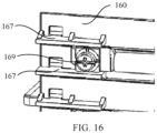
- a baffle plate 167 and a fastener 169 connected to a stationary contact assembly 110 are disposed on one side of the housing 160, and the fastener 169 is located between two baffle plates 167 of adjacent housings 160.
- the fastener 169 when the fastener 169 is connected to a stationary contact by using a wire 107, the wire 107 and the stationary contact assembly 110 are connected and fastened, to form an electrical connection path.
- the fastener 169 may be in a form of a screw in combination with a square pad.
- the baffle plate 167 When the screw is used for fastening, the baffle plate 167 may be used for limiting on the square pad, to prevent the pad from rotating along with the screw. This helps better press against the wire 107 and improve stability of an electrical connection.
- the stationary contact and the fastener 169 that are adjacent may be separated, to increase an electric clearance and a creepage distance.
- the fastener 169 may protrude from the baffle plate 167 in a height direction, or may be located in a space enclosed by two baffle plates 167.
- the fastener 169 when the fastener 169 is in a form of a screw in combination with a square pad, only the square pad needs to be disposed in a space enclosed by two baffle plates 167, to prevent the square pad from rotating correspondingly when the screw rotates.
Landscapes
- Physics & Mathematics (AREA)
- Electromagnetism (AREA)
- Switch Cases, Indication, And Locking (AREA)
Claims (13)
- Schalteinheit (100), die mindestens eine stationäre Kontaktbaugruppe (110) umfasst, wobei jede stationäre Kontaktbaugruppe (110) einen ersten stationären Kontakt (112), einen zweiten stationären Kontakt (116) und einen mit dem ersten stationären Kontakt (112) verbundenen ersten Stift (114) umfasst und der erste Stift (114) auf eine Leiterplatte (105) gelötet ist, wobei die stationäre Kontaktbaugruppe (110) ferner einen mit dem zweiten stationären Kontakt (116) verbundenen zweiten Stift (118) umfasst, der erste stationäre Kontakt (112) und der erste Stift (114) in einem Stück geformt sind, der zweite stationäre Kontakt (116) und der zweite Stift (118) in einem Stück geformt sind und der zweite Stift (118) auf die Leiterplatte (105) gelötet ist; und
wobei die Schalteinheit (100) dadurch gekennzeichnet ist, dass sie ferner ein Gehäuse (160) umfasst, der erste Stift (114) einen mit dem ersten stationären Kontakt (112) verbundenen ersten Biegeabschnitt (1142) und einen mit dem ersten Biegeabschnitt (1142) verbundenen ersten Erstreckungsabschnitt (1144) umfasst, der erste Erstreckungsabschnitt (1144) und der erste stationäre Kontakt (112) sich auf unterschiedlichen Ebenen befinden, der erste Stift (114) von einer Lichtbogenentladungsöffnung (162) des Gehäuses (160) entfernt ist, der zweite Stift (118) einen mit dem zweiten stationären Kontakt (116) verbundenen zweiten Biegeabschnitt (1182) und einen mit dem zweiten Biegeabschnitt (1182) verbundenen zweiten Erstreckungsabschnitt (1184) umfasst, der zweite Erstreckungsabschnitt (1184) und der zweite stationäre Kontakt (116) sich auf unterschiedlichen Ebenen befinden und der zweite Stift (118) von der Lichtbogenentladungsöffnung (162) entfernt ist. - Schalteinheit (100) nach Anspruch 1, wobei die stationäre Kontaktbaugruppe (110) ferner einen Verbinder (130) umfasst, ein Anschluss des Verbinders (130) mit dem zweiten stationären Kontakt (116) verbunden ist und der andere Anschluss mit der Leiterplatte (105) verbunden ist.
- Schalteinheit (100) nach Anspruch 1, wobei auf dem ersten stationären Kontakt (112) und/oder dem zweiten stationären Kontakt (116) ein Verdrahtungsanschluss (140) positioniert ist und, wenn der Verdrahtungsanschluss (140) zum Verbinden eines Drahts (107) genutzt wird, der Draht (107) sich in einer vorgegebenen Richtung erstreckt.
- Schalteinheit (100) nach Anspruch 1, wobei die Schalteinheit (100) ferner einen Hilfsstift (150) umfasst, ein Anschluss des Hilfsstifts (150) mit dem ersten stationären Kontakt (112) oder dem zweiten stationären Kontakt (116) verbunden ist und der andere Anschluss auf die Leiterplatte (105) gelötet ist.
- Schalteinheit (100) nach einem der Ansprüche 1 bis 4, wobei auf dem ersten stationären Kontakt (112) ein erster Vorsprung (1122) positioniert ist, der erste Vorsprung (1122) sich auf einer Seite des ersten stationären Kontakts (112) befindet und einer Seite zugewandt ist, auf der ein elektrischer Lichtbogen erzeugt wird, auf dem zweiten stationären Kontakt (116) ein zweiter Vorsprung (1262) positioniert ist und der zweite Vorsprung (1262) sich auf einer Seite des zweiten stationären Kontakts (116) befindet und einer Seite zugewandt ist, auf der ein elektrischer Lichtbogen erzeugt wird.
- Schalteinheit (100) nach einem der Ansprüche 1 bis 4, wobei die Schalteinheit (100) ferner einen in dem Gehäuse (160) positionierten Permanentmagnet (164) umfasst, ein Lichtbogenlöschbereich gebildet wird, wenn ein beweglicher Kontakt (170) von dem ersten stationären Kontakt (112) oder dem zweiten stationären Kontakt (116) getrennt wird, der Permanentmagnet (164) dem Lichtbogenlöschbereich entspricht und ein eingeschlossener Winkel zwischen einer geraden Linie, auf der sich eine Kraft einer magnetischen Beblasung befindet, die durch den Permanentmagnet (164) auf einen elektrischen Lichtbogen in dem Lichtbogenlöschbereich ausgeübt wird, und einer orthographischen Projektion der geraden Linie auf einer Bewegungsebene (172) des beweglichen Kontakts (170) größer als oder gleich 45 Grad und kleiner als oder gleich 135 Grad ist.
- Schalteinheit (100) nach Anspruch 1, wobei auf dem Gehäuse (160) ein Begrenzungsabschnitt positioniert und dazu ausgebildet ist, eine Position des ersten Stifts (114) und/oder des zweiten Stifts (118) zu begrenzen.
- Schalteinheit (100) nach Anspruch 7, wobei der Begrenzungsabschnitt eine Begrenzungsnut (166) und einen Klemmvorsprung (168) umfasst, die Begrenzungsnut (166) und der Klemmvorsprung (168) sich in einer Stapelrichtung separat auf zwei Seiten des Gehäuses (160) befinden, der erste Stift und/oder der zweite Stift (118) durch die Begrenzungsnut (166) hindurchgehen/hindurchgeht und, wenn Gehäuse (160) gestapelt sind, eine Begrenzungsnut (166) und ein Klemmvorsprung (168) auf nebeneinanderliegenden Gehäusen (160) festgeklemmt werden, um die Position des ersten Stifts (114) und/oder des zweiten Stifts (118) zu begrenzen; oder
wobei der Begrenzungsabschnitt ein Begrenzungsdurchgangsloch ist und der erste Stift (114) und/oder der zweite Stift (118) durch das Begrenzungsdurchgangsloch hindurchgehen/hindurchgeht. - Schalteinheit (100) nach Anspruch 6, wobei auf dem Gehäuse (160) eine Lichtbogenentladungsöffnung (162) vorgesehen ist und in dem Gehäuse (160) ein mit der Lichtbogenentladungsöffnung (162) verbundener Lichtbogenraum vorgesehen ist; und
wobei in dem Gehäuse (160) ferner eine Erhebung (165) positioniert ist und die Erhebung (165) sich in dem Lichtbogenraum befindet, sodass der Lichtbogenraum einen Kanal bildet, dessen Größe stufenweise zunimmt und dann abnimmt. - Schalteinheit (100) nach Anspruch 1, wobei der erste Erstreckungsabschnitt (1144) und der zweite Erstreckungsabschnitt (1184) sich separat aus Seiten des Gehäuses (160) herauserstrecken und der erste Erstreckungsabschnitt (1144) und der zweite Erstreckungsabschnitt (1184) sich separat auf nebeneinanderliegenden Seiten des Gehäuses (160) oder gegenüberliegenden Seiten des Gehäuses (160) befinden.
- Schalteinrichtung (200), die die Schalteinheit (100) nach einem der Ansprüche 1 bis 10 umfasst, wobei Schalteinheiten (100) unter Nutzung von Gehäusen (160) gestapelt sind.
- Schalteinrichtung (200) nach Anspruch 11, wobei die Schalteinrichtung (200) ferner eine Lichtbogenpartitionsplatte (210) umfasst, die Lichtbogenpartitionsplatte (210) eine Vielzahl von Isolationskammern (212) umfasst und die Isolationskammern (212) in einer Eins-zu-eins-Entsprechung zu ersten Stiften (114) und/oder zweiten Stiften (118) der Schalteinheiten (100) sind, um geladene Teilchen zu blockieren.
- Schalteinrichtung (200) nach Anspruch 12, wobei die Lichtbogenpartitionsplatte (210) und das Gehäuse (160) in einem Stück geformt sind oder die Lichtbogenpartitionsplatte (210) und das Gehäuse (160) separat positioniert sind.
Applications Claiming Priority (2)
| Application Number | Priority Date | Filing Date | Title |
|---|---|---|---|
| CN202011070205.9A CN112133577A (zh) | 2020-09-30 | 2020-09-30 | 一种开关单元及开关电器 |
| PCT/CN2021/117192 WO2022068542A1 (zh) | 2020-09-30 | 2021-09-08 | 一种开关单元及开关电器 |
Publications (3)
| Publication Number | Publication Date |
|---|---|
| EP4210082A1 EP4210082A1 (de) | 2023-07-12 |
| EP4210082A4 EP4210082A4 (de) | 2024-06-19 |
| EP4210082B1 true EP4210082B1 (de) | 2025-04-23 |
Family
ID=73843831
Family Applications (1)
| Application Number | Title | Priority Date | Filing Date |
|---|---|---|---|
| EP21874203.9A Active EP4210082B1 (de) | 2020-09-30 | 2021-09-08 | Schalteinheit und schaltvorrichtung |
Country Status (4)
| Country | Link |
|---|---|
| US (1) | US12381050B2 (de) |
| EP (1) | EP4210082B1 (de) |
| CN (1) | CN112133577A (de) |
| WO (1) | WO2022068542A1 (de) |
Families Citing this family (7)
| Publication number | Priority date | Publication date | Assignee | Title |
|---|---|---|---|---|
| CN112133577A (zh) | 2020-09-30 | 2020-12-25 | 上海良信电器股份有限公司 | 一种开关单元及开关电器 |
| CN115241021B (zh) * | 2021-04-23 | 2024-08-13 | 上海良信电器股份有限公司 | 一种静触头组件和断路器 |
| CN115910643A (zh) * | 2021-09-30 | 2023-04-04 | 上海良信电器股份有限公司 | 一种开关单元及开关电器 |
| CN113936932B (zh) * | 2021-11-01 | 2024-04-12 | 阳光电源股份有限公司 | 一种逆变器 |
| CN116544041A (zh) * | 2022-01-25 | 2023-08-04 | 上海良信电器股份有限公司 | 一种触头系统和旋转开关 |
| CN117375366A (zh) * | 2023-09-18 | 2024-01-09 | 华为数字能源技术有限公司 | 发电系统、功率变换器及开关组件 |
| EP4550377A1 (de) * | 2023-10-30 | 2025-05-07 | Ewac Holding B.V. | Drehschalter |
Family Cites Families (27)
| Publication number | Priority date | Publication date | Assignee | Title |
|---|---|---|---|---|
| US6605787B1 (en) * | 2002-09-10 | 2003-08-12 | Defond Manufacturing Limited | Electrical switch |
| US7442887B2 (en) * | 2005-09-26 | 2008-10-28 | Blue Sea Systems, Inc. | Enhanced rotary multi-pole electrical switch |
| US7462797B2 (en) * | 2006-03-28 | 2008-12-09 | Memie Mei Mei Wong | Electrical rotary switch |
| EP2107581B1 (de) * | 2008-04-01 | 2012-05-16 | Ewac Holding B.V. | Elektrischer Drehschalter |
| US9953789B2 (en) * | 2009-09-18 | 2018-04-24 | Schneider Electric Industries Sas | Single-pole breaking unit comprising a rotary contact bridge, and a switchgear device, and circuit breaker comprising such a unit |
| FI123561B (fi) * | 2011-06-07 | 2013-07-15 | Abb Oy | Kytkin |
| CN102891025B (zh) * | 2011-07-22 | 2016-02-10 | 西门子公司 | 一种开关装置 |
| EP2650894B1 (de) * | 2012-04-12 | 2018-06-06 | ABB Oy | Elektrische Stromschaltungsvorrichtung |
| DE102013000904B4 (de) * | 2013-01-18 | 2023-08-24 | Kostal Automobil Elektrik Gmbh & Co. Kg | Schaltkontaktfeder für einen elektrischen Schalter sowie entsprechender Schalter |
| WO2014170529A1 (en) * | 2013-04-15 | 2014-10-23 | Abb Oy | Electric switch housing |
| US9299509B2 (en) * | 2013-05-23 | 2016-03-29 | Socomec S.A. | Electrical switching device, notably for direct current, equipped with a magnetic module for blowing the electric arc |
| TW201503197A (zh) * | 2013-07-02 | 2015-01-16 | Switchlab Inc | 開關改良結構 |
| EP3104386B1 (de) * | 2015-06-08 | 2018-10-17 | Giovenzana International B.V. | Nockendrehschalter mit auf einer elektroleiterplatte lötbaren doppelten positiven unterbrecherkontakten |
| CN105702488B (zh) * | 2016-03-30 | 2018-03-27 | 上海电科电器科技有限公司 | 控制与保护开关电器的内部反馈装置 |
| CN105742107B (zh) * | 2016-04-08 | 2018-12-07 | 首瑞(天津)电气设备有限公司 | 用于旋转隔离开关的触头模块和旋转隔离开关 |
| CN205828332U (zh) * | 2016-07-20 | 2016-12-21 | 程伟 | 万能式断路器中隔弧板在绝缘件上的固定机构 |
| EP3364437B1 (de) * | 2017-02-17 | 2023-07-26 | Ewac Holding B.V. | Drehschalter |
| CN107424861A (zh) * | 2017-08-03 | 2017-12-01 | 上海良信电器股份有限公司 | 一种带有增磁块的旋转式隔离开关触头模块 |
| CN107591275A (zh) * | 2017-08-03 | 2018-01-16 | 上海良信电器股份有限公司 | 一种设有灭弧装置的旋转式隔离开关触头模块 |
| CN208014602U (zh) * | 2017-12-20 | 2018-10-26 | 上海良信电器股份有限公司 | 旋转式隔离开关触头模块 |
| EP3561831B1 (de) * | 2018-04-24 | 2022-10-26 | ABB Schweiz AG | Elektrischer schalter |
| CN109637871A (zh) * | 2019-01-10 | 2019-04-16 | 北京光华世通科技有限公司 | 一种小型直流开关 |
| CN211294934U (zh) * | 2019-12-05 | 2020-08-18 | 通力股份公司 | 用于凸轮开关的具有一体化结构的固定触头和凸轮开关 |
| CN110853964B (zh) * | 2019-12-23 | 2024-11-05 | 上海伊莱克斯实业有限公司 | 一种旋钮型切换开关 |
| CN112133577A (zh) * | 2020-09-30 | 2020-12-25 | 上海良信电器股份有限公司 | 一种开关单元及开关电器 |
| CN213242289U (zh) * | 2020-09-30 | 2021-05-18 | 上海良信电器股份有限公司 | 一种开关单元及开关电器 |
| CN214226799U (zh) * | 2020-12-18 | 2021-09-17 | 上海良信电器股份有限公司 | 一种开关单元及旋转开关 |
-
2020
- 2020-09-30 CN CN202011070205.9A patent/CN112133577A/zh active Pending
-
2021
- 2021-09-08 EP EP21874203.9A patent/EP4210082B1/de active Active
- 2021-09-08 WO PCT/CN2021/117192 patent/WO2022068542A1/zh not_active Ceased
-
2023
- 2023-03-29 US US18/192,513 patent/US12381050B2/en active Active
Also Published As
| Publication number | Publication date |
|---|---|
| US12381050B2 (en) | 2025-08-05 |
| EP4210082A4 (de) | 2024-06-19 |
| US20230238200A1 (en) | 2023-07-27 |
| EP4210082A1 (de) | 2023-07-12 |
| CN112133577A (zh) | 2020-12-25 |
| WO2022068542A1 (zh) | 2022-04-07 |
Similar Documents
| Publication | Publication Date | Title |
|---|---|---|
| EP4210082B1 (de) | Schalteinheit und schaltvorrichtung | |
| CN214226799U (zh) | 一种开关单元及旋转开关 | |
| EP1632972B1 (de) | Anschlussanordnung für Schutzschalter mit Entlüftungskanalen und Schutzschalter mit einer solchen Anschlussanordnung | |
| US20150270075A1 (en) | Modular gas exhaust assembly for a circuit breaker | |
| CN108417429B (zh) | 旋转式电气开关 | |
| CN213242289U (zh) | 一种开关单元及开关电器 | |
| CN114649153A (zh) | 一种开关 | |
| EP4152357B1 (de) | Schutzschalter und stromverteilungssystem | |
| CN114649160A (zh) | 一种开关单元及旋转开关 | |
| CN117457453B (zh) | 断路器的灭弧结构和断路器 | |
| KR20180113899A (ko) | 회로 차단기 | |
| CN117877937A (zh) | 一种塑壳断路器单极模块和断路器 | |
| CN216212968U (zh) | 一种开关单元及开关电器 | |
| CN213936096U (zh) | 一种断路器 | |
| CN117276024A (zh) | 触头装置及开关电器 | |
| CN118888406B (zh) | 一种模数化拼装的直流框架断路器 | |
| CN218769359U (zh) | 一种断路器 | |
| JP7019095B2 (ja) | 接続変換アダプタおよび電気機器 | |
| CN223785021U (zh) | 开关器件及电力系统 | |
| CN224177304U (zh) | 一种用于断路器的隔弧罩和一种断路器 | |
| CN221596358U (zh) | 一种塑壳断路器静触头结构 | |
| CN217182130U (zh) | 断路器的静触头灭弧模块 | |
| CN219203078U (zh) | 一种用于塑壳断路器的零飞弧罩 | |
| CN112614765A (zh) | 一种断路器的静触头灭弧模块 | |
| CN223471551U (zh) | 静触头组件及开关设备 |
Legal Events
| Date | Code | Title | Description |
|---|---|---|---|
| STAA | Information on the status of an ep patent application or granted ep patent |
Free format text: STATUS: THE INTERNATIONAL PUBLICATION HAS BEEN MADE |
|
| PUAI | Public reference made under article 153(3) epc to a published international application that has entered the european phase |
Free format text: ORIGINAL CODE: 0009012 |
|
| STAA | Information on the status of an ep patent application or granted ep patent |
Free format text: STATUS: REQUEST FOR EXAMINATION WAS MADE |
|
| 17P | Request for examination filed |
Effective date: 20230406 |
|
| AK | Designated contracting states |
Kind code of ref document: A1 Designated state(s): AL AT BE BG CH CY CZ DE DK EE ES FI FR GB GR HR HU IE IS IT LI LT LU LV MC MK MT NL NO PL PT RO RS SE SI SK SM TR |
|
| TPAC | Observations filed by third parties |
Free format text: ORIGINAL CODE: EPIDOSNTIPA |
|
| DAV | Request for validation of the european patent (deleted) | ||
| DAX | Request for extension of the european patent (deleted) | ||
| A4 | Supplementary search report drawn up and despatched |
Effective date: 20240522 |
|
| RIC1 | Information provided on ipc code assigned before grant |
Ipc: H01H 1/36 20060101ALN20240515BHEP Ipc: H01H 9/34 20060101ALN20240515BHEP Ipc: H01H 1/58 20060101ALI20240515BHEP Ipc: H01H 19/64 20060101ALI20240515BHEP Ipc: H01H 19/08 20060101AFI20240515BHEP |
|
| GRAP | Despatch of communication of intention to grant a patent |
Free format text: ORIGINAL CODE: EPIDOSNIGR1 |
|
| STAA | Information on the status of an ep patent application or granted ep patent |
Free format text: STATUS: GRANT OF PATENT IS INTENDED |
|
| RIC1 | Information provided on ipc code assigned before grant |
Ipc: H01H 1/36 20060101ALN20241210BHEP Ipc: H01H 9/34 20060101ALN20241210BHEP Ipc: H01H 1/58 20060101ALI20241210BHEP Ipc: H01H 19/64 20060101ALI20241210BHEP Ipc: H01H 19/08 20060101AFI20241210BHEP |
|
| INTG | Intention to grant announced |
Effective date: 20241219 |
|
| GRAS | Grant fee paid |
Free format text: ORIGINAL CODE: EPIDOSNIGR3 |
|
| GRAA | (expected) grant |
Free format text: ORIGINAL CODE: 0009210 |
|
| STAA | Information on the status of an ep patent application or granted ep patent |
Free format text: STATUS: THE PATENT HAS BEEN GRANTED |
|
| AK | Designated contracting states |
Kind code of ref document: B1 Designated state(s): AL AT BE BG CH CY CZ DE DK EE ES FI FR GB GR HR HU IE IS IT LI LT LU LV MC MK MT NL NO PL PT RO RS SE SI SK SM TR |
|
| REG | Reference to a national code |
Ref country code: GB Ref legal event code: FG4D |
|
| REG | Reference to a national code |
Ref country code: CH Ref legal event code: EP |
|
| REG | Reference to a national code |
Ref country code: DE Ref legal event code: R096 Ref document number: 602021029788 Country of ref document: DE |
|
| REG | Reference to a national code |
Ref country code: IE Ref legal event code: FG4D |
|
| REG | Reference to a national code |
Ref country code: NL Ref legal event code: MP Effective date: 20250423 |
|
| PG25 | Lapsed in a contracting state [announced via postgrant information from national office to epo] |
Ref country code: NL Free format text: LAPSE BECAUSE OF FAILURE TO SUBMIT A TRANSLATION OF THE DESCRIPTION OR TO PAY THE FEE WITHIN THE PRESCRIBED TIME-LIMIT Effective date: 20250423 |
|
| REG | Reference to a national code |
Ref country code: AT Ref legal event code: MK05 Ref document number: 1788648 Country of ref document: AT Kind code of ref document: T Effective date: 20250423 |
|
| PG25 | Lapsed in a contracting state [announced via postgrant information from national office to epo] |
Ref country code: FI Free format text: LAPSE BECAUSE OF FAILURE TO SUBMIT A TRANSLATION OF THE DESCRIPTION OR TO PAY THE FEE WITHIN THE PRESCRIBED TIME-LIMIT Effective date: 20250423 Ref country code: ES Free format text: LAPSE BECAUSE OF FAILURE TO SUBMIT A TRANSLATION OF THE DESCRIPTION OR TO PAY THE FEE WITHIN THE PRESCRIBED TIME-LIMIT Effective date: 20250423 Ref country code: PT Free format text: LAPSE BECAUSE OF FAILURE TO SUBMIT A TRANSLATION OF THE DESCRIPTION OR TO PAY THE FEE WITHIN THE PRESCRIBED TIME-LIMIT Effective date: 20250825 |
|
| PGFP | Annual fee paid to national office [announced via postgrant information from national office to epo] |
Ref country code: DE Payment date: 20250730 Year of fee payment: 5 |
|
| REG | Reference to a national code |
Ref country code: LT Ref legal event code: MG9D |
|
| PG25 | Lapsed in a contracting state [announced via postgrant information from national office to epo] |
Ref country code: GR Free format text: LAPSE BECAUSE OF FAILURE TO SUBMIT A TRANSLATION OF THE DESCRIPTION OR TO PAY THE FEE WITHIN THE PRESCRIBED TIME-LIMIT Effective date: 20250724 Ref country code: NO Free format text: LAPSE BECAUSE OF FAILURE TO SUBMIT A TRANSLATION OF THE DESCRIPTION OR TO PAY THE FEE WITHIN THE PRESCRIBED TIME-LIMIT Effective date: 20250723 |
|
| PG25 | Lapsed in a contracting state [announced via postgrant information from national office to epo] |
Ref country code: PL Free format text: LAPSE BECAUSE OF FAILURE TO SUBMIT A TRANSLATION OF THE DESCRIPTION OR TO PAY THE FEE WITHIN THE PRESCRIBED TIME-LIMIT Effective date: 20250423 |
|
| PG25 | Lapsed in a contracting state [announced via postgrant information from national office to epo] |
Ref country code: BG Free format text: LAPSE BECAUSE OF FAILURE TO SUBMIT A TRANSLATION OF THE DESCRIPTION OR TO PAY THE FEE WITHIN THE PRESCRIBED TIME-LIMIT Effective date: 20250423 |
|
| PG25 | Lapsed in a contracting state [announced via postgrant information from national office to epo] |
Ref country code: HR Free format text: LAPSE BECAUSE OF FAILURE TO SUBMIT A TRANSLATION OF THE DESCRIPTION OR TO PAY THE FEE WITHIN THE PRESCRIBED TIME-LIMIT Effective date: 20250423 |
|
| PG25 | Lapsed in a contracting state [announced via postgrant information from national office to epo] |
Ref country code: AT Free format text: LAPSE BECAUSE OF FAILURE TO SUBMIT A TRANSLATION OF THE DESCRIPTION OR TO PAY THE FEE WITHIN THE PRESCRIBED TIME-LIMIT Effective date: 20250423 |
|
| PG25 | Lapsed in a contracting state [announced via postgrant information from national office to epo] |
Ref country code: RS Free format text: LAPSE BECAUSE OF FAILURE TO SUBMIT A TRANSLATION OF THE DESCRIPTION OR TO PAY THE FEE WITHIN THE PRESCRIBED TIME-LIMIT Effective date: 20250723 |
|
| PG25 | Lapsed in a contracting state [announced via postgrant information from national office to epo] |
Ref country code: IS Free format text: LAPSE BECAUSE OF FAILURE TO SUBMIT A TRANSLATION OF THE DESCRIPTION OR TO PAY THE FEE WITHIN THE PRESCRIBED TIME-LIMIT Effective date: 20250823 |
|
| PG25 | Lapsed in a contracting state [announced via postgrant information from national office to epo] |
Ref country code: LV Free format text: LAPSE BECAUSE OF FAILURE TO SUBMIT A TRANSLATION OF THE DESCRIPTION OR TO PAY THE FEE WITHIN THE PRESCRIBED TIME-LIMIT Effective date: 20250423 |
|
| PG25 | Lapsed in a contracting state [announced via postgrant information from national office to epo] |
Ref country code: DK Free format text: LAPSE BECAUSE OF FAILURE TO SUBMIT A TRANSLATION OF THE DESCRIPTION OR TO PAY THE FEE WITHIN THE PRESCRIBED TIME-LIMIT Effective date: 20250423 Ref country code: SM Free format text: LAPSE BECAUSE OF FAILURE TO SUBMIT A TRANSLATION OF THE DESCRIPTION OR TO PAY THE FEE WITHIN THE PRESCRIBED TIME-LIMIT Effective date: 20250423 |
|
| PG25 | Lapsed in a contracting state [announced via postgrant information from national office to epo] |
Ref country code: CZ Free format text: LAPSE BECAUSE OF FAILURE TO SUBMIT A TRANSLATION OF THE DESCRIPTION OR TO PAY THE FEE WITHIN THE PRESCRIBED TIME-LIMIT Effective date: 20250423 |
|
| PG25 | Lapsed in a contracting state [announced via postgrant information from national office to epo] |
Ref country code: EE Free format text: LAPSE BECAUSE OF FAILURE TO SUBMIT A TRANSLATION OF THE DESCRIPTION OR TO PAY THE FEE WITHIN THE PRESCRIBED TIME-LIMIT Effective date: 20250423 |
|
| REG | Reference to a national code |
Ref country code: DE Ref legal event code: R097 Ref document number: 602021029788 Country of ref document: DE |
|
| PG25 | Lapsed in a contracting state [announced via postgrant information from national office to epo] |
Ref country code: SK Free format text: LAPSE BECAUSE OF FAILURE TO SUBMIT A TRANSLATION OF THE DESCRIPTION OR TO PAY THE FEE WITHIN THE PRESCRIBED TIME-LIMIT Effective date: 20250423 |
|
| PG25 | Lapsed in a contracting state [announced via postgrant information from national office to epo] |
Ref country code: IT Free format text: LAPSE BECAUSE OF FAILURE TO SUBMIT A TRANSLATION OF THE DESCRIPTION OR TO PAY THE FEE WITHIN THE PRESCRIBED TIME-LIMIT Effective date: 20250423 |
|
| PLBE | No opposition filed within time limit |
Free format text: ORIGINAL CODE: 0009261 |
|
| STAA | Information on the status of an ep patent application or granted ep patent |
Free format text: STATUS: NO OPPOSITION FILED WITHIN TIME LIMIT |
|
| REG | Reference to a national code |
Ref country code: CH Ref legal event code: L10 Free format text: ST27 STATUS EVENT CODE: U-0-0-L10-L00 (AS PROVIDED BY THE NATIONAL OFFICE) Effective date: 20260304 |
|
| PG25 | Lapsed in a contracting state [announced via postgrant information from national office to epo] |
Ref country code: RO Free format text: LAPSE BECAUSE OF FAILURE TO SUBMIT A TRANSLATION OF THE DESCRIPTION OR TO PAY THE FEE WITHIN THE PRESCRIBED TIME-LIMIT Effective date: 20250423 |
|
| 26N | No opposition filed |
Effective date: 20260126 |