EP4210152A1 - Module de batterie et bloc-batterie le comprenant - Google Patents
Module de batterie et bloc-batterie le comprenant Download PDFInfo
- Publication number
- EP4210152A1 EP4210152A1 EP22775934.7A EP22775934A EP4210152A1 EP 4210152 A1 EP4210152 A1 EP 4210152A1 EP 22775934 A EP22775934 A EP 22775934A EP 4210152 A1 EP4210152 A1 EP 4210152A1
- Authority
- EP
- European Patent Office
- Prior art keywords
- battery cell
- cell stack
- battery
- recessed part
- frame
- Prior art date
- Legal status (The legal status is an assumption and is not a legal conclusion. Google has not performed a legal analysis and makes no representation as to the accuracy of the status listed.)
- Granted
Links
Images








Classifications
-
- H—ELECTRICITY
- H01—ELECTRIC ELEMENTS
- H01M—PROCESSES OR MEANS, e.g. BATTERIES, FOR THE DIRECT CONVERSION OF CHEMICAL ENERGY INTO ELECTRICAL ENERGY
- H01M10/00—Secondary cells; Manufacture thereof
- H01M10/60—Heating or cooling; Temperature control
- H01M10/65—Means for temperature control structurally associated with the cells
- H01M10/656—Means for temperature control structurally associated with the cells characterised by the type of heat-exchange fluid
- H01M10/6567—Liquids
- H01M10/6568—Liquids characterised by flow circuits, e.g. loops, located externally to the cells or cell casings
-
- H—ELECTRICITY
- H01—ELECTRIC ELEMENTS
- H01M—PROCESSES OR MEANS, e.g. BATTERIES, FOR THE DIRECT CONVERSION OF CHEMICAL ENERGY INTO ELECTRICAL ENERGY
- H01M10/00—Secondary cells; Manufacture thereof
- H01M10/60—Heating or cooling; Temperature control
- H01M10/65—Means for temperature control structurally associated with the cells
- H01M10/655—Solid structures for heat exchange or heat conduction
- H01M10/6556—Solid parts with flow channel passages or pipes for heat exchange
- H01M10/6557—Solid parts with flow channel passages or pipes for heat exchange arranged between the cells
-
- H—ELECTRICITY
- H01—ELECTRIC ELEMENTS
- H01M—PROCESSES OR MEANS, e.g. BATTERIES, FOR THE DIRECT CONVERSION OF CHEMICAL ENERGY INTO ELECTRICAL ENERGY
- H01M50/00—Constructional details or processes of manufacture of the non-active parts of electrochemical cells other than fuel cells, e.g. hybrid cells
- H01M50/20—Mountings; Secondary casings or frames; Racks, modules or packs; Suspension devices; Shock absorbers; Transport or carrying devices; Holders
- H01M50/204—Racks, modules or packs for multiple batteries or multiple cells
- H01M50/207—Racks, modules or packs for multiple batteries or multiple cells characterised by their shape
- H01M50/211—Racks, modules or packs for multiple batteries or multiple cells characterised by their shape adapted for pouch cells
-
- H—ELECTRICITY
- H01—ELECTRIC ELEMENTS
- H01M—PROCESSES OR MEANS, e.g. BATTERIES, FOR THE DIRECT CONVERSION OF CHEMICAL ENERGY INTO ELECTRICAL ENERGY
- H01M10/00—Secondary cells; Manufacture thereof
- H01M10/42—Methods or arrangements for servicing or maintenance of secondary cells or secondary half-cells
-
- H—ELECTRICITY
- H01—ELECTRIC ELEMENTS
- H01M—PROCESSES OR MEANS, e.g. BATTERIES, FOR THE DIRECT CONVERSION OF CHEMICAL ENERGY INTO ELECTRICAL ENERGY
- H01M10/00—Secondary cells; Manufacture thereof
- H01M10/42—Methods or arrangements for servicing or maintenance of secondary cells or secondary half-cells
- H01M10/4207—Methods or arrangements for servicing or maintenance of secondary cells or secondary half-cells for several batteries or cells simultaneously or sequentially
-
- H—ELECTRICITY
- H01—ELECTRIC ELEMENTS
- H01M—PROCESSES OR MEANS, e.g. BATTERIES, FOR THE DIRECT CONVERSION OF CHEMICAL ENERGY INTO ELECTRICAL ENERGY
- H01M10/00—Secondary cells; Manufacture thereof
- H01M10/60—Heating or cooling; Temperature control
- H01M10/61—Types of temperature control
- H01M10/613—Cooling or keeping cold
-
- H—ELECTRICITY
- H01—ELECTRIC ELEMENTS
- H01M—PROCESSES OR MEANS, e.g. BATTERIES, FOR THE DIRECT CONVERSION OF CHEMICAL ENERGY INTO ELECTRICAL ENERGY
- H01M10/00—Secondary cells; Manufacture thereof
- H01M10/60—Heating or cooling; Temperature control
- H01M10/62—Heating or cooling; Temperature control specially adapted for specific applications
- H01M10/625—Vehicles
-
- H—ELECTRICITY
- H01—ELECTRIC ELEMENTS
- H01M—PROCESSES OR MEANS, e.g. BATTERIES, FOR THE DIRECT CONVERSION OF CHEMICAL ENERGY INTO ELECTRICAL ENERGY
- H01M10/00—Secondary cells; Manufacture thereof
- H01M10/60—Heating or cooling; Temperature control
- H01M10/64—Heating or cooling; Temperature control characterised by the shape of the cells
- H01M10/647—Prismatic or flat cells, e.g. pouch cells
-
- H—ELECTRICITY
- H01—ELECTRIC ELEMENTS
- H01M—PROCESSES OR MEANS, e.g. BATTERIES, FOR THE DIRECT CONVERSION OF CHEMICAL ENERGY INTO ELECTRICAL ENERGY
- H01M10/00—Secondary cells; Manufacture thereof
- H01M10/60—Heating or cooling; Temperature control
- H01M10/65—Means for temperature control structurally associated with the cells
- H01M10/655—Solid structures for heat exchange or heat conduction
- H01M10/6554—Rods or plates
-
- H—ELECTRICITY
- H01—ELECTRIC ELEMENTS
- H01M—PROCESSES OR MEANS, e.g. BATTERIES, FOR THE DIRECT CONVERSION OF CHEMICAL ENERGY INTO ELECTRICAL ENERGY
- H01M10/00—Secondary cells; Manufacture thereof
- H01M10/60—Heating or cooling; Temperature control
- H01M10/65—Means for temperature control structurally associated with the cells
- H01M10/655—Solid structures for heat exchange or heat conduction
- H01M10/6556—Solid parts with flow channel passages or pipes for heat exchange
-
- H—ELECTRICITY
- H01—ELECTRIC ELEMENTS
- H01M—PROCESSES OR MEANS, e.g. BATTERIES, FOR THE DIRECT CONVERSION OF CHEMICAL ENERGY INTO ELECTRICAL ENERGY
- H01M10/00—Secondary cells; Manufacture thereof
- H01M10/60—Heating or cooling; Temperature control
- H01M10/65—Means for temperature control structurally associated with the cells
- H01M10/656—Means for temperature control structurally associated with the cells characterised by the type of heat-exchange fluid
- H01M10/6567—Liquids
-
- H—ELECTRICITY
- H01—ELECTRIC ELEMENTS
- H01M—PROCESSES OR MEANS, e.g. BATTERIES, FOR THE DIRECT CONVERSION OF CHEMICAL ENERGY INTO ELECTRICAL ENERGY
- H01M50/00—Constructional details or processes of manufacture of the non-active parts of electrochemical cells other than fuel cells, e.g. hybrid cells
- H01M50/20—Mountings; Secondary casings or frames; Racks, modules or packs; Suspension devices; Shock absorbers; Transport or carrying devices; Holders
- H01M50/204—Racks, modules or packs for multiple batteries or multiple cells
-
- H—ELECTRICITY
- H01—ELECTRIC ELEMENTS
- H01M—PROCESSES OR MEANS, e.g. BATTERIES, FOR THE DIRECT CONVERSION OF CHEMICAL ENERGY INTO ELECTRICAL ENERGY
- H01M50/00—Constructional details or processes of manufacture of the non-active parts of electrochemical cells other than fuel cells, e.g. hybrid cells
- H01M50/20—Mountings; Secondary casings or frames; Racks, modules or packs; Suspension devices; Shock absorbers; Transport or carrying devices; Holders
- H01M50/204—Racks, modules or packs for multiple batteries or multiple cells
- H01M50/207—Racks, modules or packs for multiple batteries or multiple cells characterised by their shape
- H01M50/209—Racks, modules or packs for multiple batteries or multiple cells characterised by their shape adapted for prismatic or rectangular cells
-
- H—ELECTRICITY
- H01—ELECTRIC ELEMENTS
- H01M—PROCESSES OR MEANS, e.g. BATTERIES, FOR THE DIRECT CONVERSION OF CHEMICAL ENERGY INTO ELECTRICAL ENERGY
- H01M50/00—Constructional details or processes of manufacture of the non-active parts of electrochemical cells other than fuel cells, e.g. hybrid cells
- H01M50/20—Mountings; Secondary casings or frames; Racks, modules or packs; Suspension devices; Shock absorbers; Transport or carrying devices; Holders
- H01M50/258—Modular batteries; Casings provided with means for assembling
-
- H—ELECTRICITY
- H01—ELECTRIC ELEMENTS
- H01M—PROCESSES OR MEANS, e.g. BATTERIES, FOR THE DIRECT CONVERSION OF CHEMICAL ENERGY INTO ELECTRICAL ENERGY
- H01M50/00—Constructional details or processes of manufacture of the non-active parts of electrochemical cells other than fuel cells, e.g. hybrid cells
- H01M50/20—Mountings; Secondary casings or frames; Racks, modules or packs; Suspension devices; Shock absorbers; Transport or carrying devices; Holders
- H01M50/271—Lids or covers for the racks or secondary casings
-
- H—ELECTRICITY
- H01—ELECTRIC ELEMENTS
- H01M—PROCESSES OR MEANS, e.g. BATTERIES, FOR THE DIRECT CONVERSION OF CHEMICAL ENERGY INTO ELECTRICAL ENERGY
- H01M50/00—Constructional details or processes of manufacture of the non-active parts of electrochemical cells other than fuel cells, e.g. hybrid cells
- H01M50/20—Mountings; Secondary casings or frames; Racks, modules or packs; Suspension devices; Shock absorbers; Transport or carrying devices; Holders
- H01M50/296—Mountings; Secondary casings or frames; Racks, modules or packs; Suspension devices; Shock absorbers; Transport or carrying devices; Holders characterised by terminals of battery packs
-
- H—ELECTRICITY
- H01—ELECTRIC ELEMENTS
- H01M—PROCESSES OR MEANS, e.g. BATTERIES, FOR THE DIRECT CONVERSION OF CHEMICAL ENERGY INTO ELECTRICAL ENERGY
- H01M2220/00—Batteries for particular applications
- H01M2220/20—Batteries in motive systems, e.g. vehicle, ship, plane
-
- Y—GENERAL TAGGING OF NEW TECHNOLOGICAL DEVELOPMENTS; GENERAL TAGGING OF CROSS-SECTIONAL TECHNOLOGIES SPANNING OVER SEVERAL SECTIONS OF THE IPC; TECHNICAL SUBJECTS COVERED BY FORMER USPC CROSS-REFERENCE ART COLLECTIONS [XRACs] AND DIGESTS
- Y02—TECHNOLOGIES OR APPLICATIONS FOR MITIGATION OR ADAPTATION AGAINST CLIMATE CHANGE
- Y02E—REDUCTION OF GREENHOUSE GAS [GHG] EMISSIONS, RELATED TO ENERGY GENERATION, TRANSMISSION OR DISTRIBUTION
- Y02E60/00—Enabling technologies; Technologies with a potential or indirect contribution to GHG emissions mitigation
- Y02E60/10—Energy storage using batteries
Definitions
- the present disclosure relates to a battery module and a battery pack including the same, and more particularly to a battery module having improved space utilization and cooling efficiency and a battery pack including the same.
- chargeable/dischargeable secondary batteries are used as a power source for an electric vehicle (EV), a hybrid electric vehicle (HEV), a plug-in hybrid electric vehicle (P-HEV) and the like, in an attempt to solve air pollution and the like caused by existing gasoline vehicles using fossil fuel. Therefore, the demand for development of the secondary battery is growing.
- EV electric vehicle
- HEV hybrid electric vehicle
- P-HEV plug-in hybrid electric vehicle
- the lithium secondary battery has come into the spotlight because they have advantages, for example, hardly exhibiting memory effects compared to nickel-based secondary batteries and thus being freely charged and discharged, and having very low self-discharge rate and high energy density.
- Such lithium secondary battery mainly uses a lithium-based oxide and a carbonaceous material as a cathode active material and an anode active material, respectively.
- the lithium secondary battery includes an electrode assembly in which a cathode plate and an anode plate, each being coated with the cathode active material and the anode active material, are arranged with a separator being interposed between them, and a battery case which seals and houses the electrode assembly together with an electrolytic solution.
- the lithium secondary battery may be classified based on the shape of the exterior material into a can-type secondary battery in which the electrode assembly is mounted in a metal can, and a pouch-type secondary battery in which the electrode assembly is mounted in a pouch of an aluminum laminate sheet.
- a battery module in which a large number of battery cells are electrically connected is used.
- a large number of battery cells are connected to each other in series or parallel to form a cell assembly, thereby improving capacity and output.
- One or more battery modules can be mounted together with various control and protection systems such as a BDU(battery disconnect unit), a BMS (battery management system) and a cooling system to form a battery pack.
- a battery module includes an upper battery cell stack and a lower battery cell stack in which a plurality of battery cells are stacked; a cooling flow path located between the upper battery cell stack and the lower battery cell stack; and a module frame in which the upper battery cell stack and the lower battery cell stack are housed.
- An inlet port for supplying a refrigerant to the cooling flow path and an outlet port for discharging the refrigerant from the cooling flow path are located opposite to each other, so that the refrigerant flows in one direction in the cooling flow path.
- a longitudinal direction of the battery cell is in parallel with the one direction in which the refrigerant flows.
- the refrigerant may flow in a straight line in the cooling flow path.
- the refrigerant may flow in a curved line along the one direction.
- the module frame may include an upper frame in which the upper battery cell stack is housed and a lower frame in which the lower battery cell stack is housed, and the cooling flow path may be formed between the upper frame and the lower frame.
- the upper frame may include an upper plate that is located on the lower surface of the bottom part of the upper frame, and an upper recessed part that is recessed upward from the upper plate.
- the lower frame may include a lower plate that is located on the upper surface of the ceiling part of the lower frame, and a lower recessed part that is recessed downward from the lower plate. The upper plate and the lower plate are joined so that the upper recessed part and the lower recessed part can form the cooling flow path.
- the battery module may further include an upper cover that covers the opened portion of the upper frame and a lower cover that covers the opened portion of the lower frame.
- the upper battery cell stack may include a first upper battery cell stack and a second upper battery cell stack.
- the lower battery cell stack may include a first lower battery cell stack and a second lower battery cell stack.
- the upper cover may include an upper recessed part that is recessed downward between the first upper battery cell stack and the second upper battery cell stack.
- the lower cover may include a lower recessed part that is recessed upward recessed between the first lower battery cell stack and the second lower battery cell stack.
- Each of the first upper battery cell stack and the second upper battery cell stack may include an electrode terminal and a module connector exposed toward the upper recessed part.
- Each of the first lower battery cell stack and the second lower battery cell stack may include an electrode terminal and a module connector exposed toward the lower recessed part.
- a HV (high voltage) connection for connecting the electrode terminals and a LV (low voltage) connection for connecting the module connector may be formed in each of the upper recessed part and the lower recessed part.
- the first upper battery cell stack and the second upper battery cell stack may be spatially separated by the upper recessed part.
- the first lower battery cell stack and the second lower battery cell stack may be spatially separated by the lower recessed part.
- a mounting hole for mounting coupling may be formed in each of the upper recessed part and the lower recessed part.
- the mounting hole of the upper recessed part and the mounting hole of the lower recessed part may be located so as to correspond to each other.
- the upper cover may include a first upper protrusion part located on one side and a second upper protrusion part located on the other side opposite to the one side.
- the inlet port may be located in the first upper protrusion part, and the outlet port may be located in the second upper protrusion part.
- the lower cover may include a first lower protrusion part located so as to correspond to the first upper protrusion part, and a second lower protrusion part located so as to correspond to the second upper protrusion part.
- a mounting hole for mounting coupling may be formed in each of the first upper protrusion part and the first lower protrusion part.
- a mounting hole for mounting coupling may be formed in each of the second upper protrusion part and the second lower protrusion part.
- the battery cell stack is arranged in a two-stage structure and the cooling flow path is arranged so as to share between them, thereby capable of improving space utilization and cooling efficiency.
- the cooling flow is configured so as to flow in one direction, thereby capable of reducing the pressure drop of the refrigerant.
- planar when referred to as “planar”, it means when a target portion is viewed from the upper side, and when referred to as “cross-sectional”, it means when a target portion is viewed from the side of a cross section cut vertically.
- Fig. 1 is a perspective view showing a battery module according to an embodiment of the present disclosure.
- Fig. 2 is a diagram which shows the battery module of Fig. 1 by changing the viewing angles.
- Fig. 3 is an exploded perspective view of the battery module of Fig. 1 .
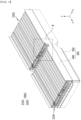
- Fig. 4 is a perspective view showing a state in which the upper cover is removed from the battery module of Fig. 3 .
- a battery module 100 includes an upper battery cell stack 200U and a lower battery cell stack 200L in which a plurality of battery cells are stacked; a cooling flow path P located between the upper battery cell stack 200U and the lower battery cell stack 200L; and a module frame 300 in which the upper battery cell stack 200U and the lower battery cell stack 200L are housed.
- the cooling flow path P refers to a passage through which the refrigerant moves.
- the refrigerant is a medium for cooling, and may be cooling water as an example.
- the upper battery cell stack 200U and the lower battery cell stack 200L can be respectively formed by stacking a plurality of battery cells in one direction.
- the battery cell will be described in detail later with reference to Figs. 5 and 6 .
- the module frame 300 may include an upper frame 400 in which the upper battery cell stack 200U is housed, and a lower frame 500 in which the lower battery cell stack 200L is housed.
- a cooling flow path P may be formed between the upper frame 400 and the lower frame 500.
- Fig. 5 is a partial view which enlarges and shows a section "B" of Fig. 4 .
- Fig. 6 is a diagram which shows a battery cell included in the battery module of Fig. 3 .
- the battery cells 110 may be stacked in plural numbers to form an upper battery cell stack 200U and a lower battery cell stack 200L, respectively.
- the upper battery cell stack 200U is located above the lower battery cell stack 200L.
- the upper battery cell stack 200U may include a first upper battery cell stack 210U and a second upper battery cell stack 220U
- the lower battery cell stack 200L may include a first lower battery cell stack 210L and a second lower battery cell stack 220L.
- the battery cells 110 can be stacked to form a total of four battery cell stacks 210U, 220U, 210L and 220L.
- the first upper battery cell stack 210U may be located above the first lower battery cell stack 210L
- the second upper battery cell stack 220U may be located above the second lower battery cell stack 220L.
- the battery cell 110 is preferably a pouch-type battery cell, and can be formed in a rectangular sheet-like structure.
- the battery cell 110 according to the present embodiment has a structure in which two electrode leads 111 and 112 face each other and protrude from one end part 114a and the other end part 114b of the cell main body 113, respectively. That is, the battery cell 110 includes electrode leads 111 and 112 that are protruded in mutually opposite directions. More specifically, the electrode leads 111 and 112 are connected to an electrode assembly (not shown), and are protruded from the electrode assembly (not shown) to the outside of the battery cell 110.
- the battery cell 110 can be produced by joining both end parts 114a and 114b of a cell case 114 and one side part 114c connecting them in a state in which an electrode assembly (not shown) is housed in a cell case 114.
- the battery cell 110 according to the present embodiment has a total of three sealing parts 114sa, 114sb and 114sc, wherein the sealing parts 114sa, 114sb and 114sc have a structure that is sealed by a method such as heat-sealing, and the remaining other side part may be composed of a connection part 115.
- the cell case 114 may be composed of a laminated sheet including a resin layer and a metal layer.
- the connection part 115 may extend long along one edge of the battery cell 110, and a bat ear 110p may be formed at an end of the connection part 115.
- Such a battery cell 110 may be formed in plural numbers, and the plurality of battery cells 110 can be stacked so as to be electrically connected to each other, thereby forming an upper battery cell stack 200U and a lower battery cell stack 200L.
- a plurality of battery cells 110 may be stacked along the direction parallel to the y-axis.
- the electrode leads 111 and 112 may protrude in the x-axis direction and the -x-axis direction, respectively.
- the upper battery cell stack 200U and the lower battery cell stack 200L may be a large-area module in which the number of battery cells 110 is increased compared to a conventional case. Specifically, 32 to 48 battery cells 110 may be included per battery cell stack. In the case of such a large-area module, the horizontal length of the battery module becomes long.
- the horizontal length may mean a length in the direction in which the battery cells 110 are stacked, that is, in a direction parallel to the x-axis.
- a direction parallel to the protruding direction of the electrode leads 111 and 112 is referred to as a longitudinal direction d1 of the battery cell 110.
- the longitudinal direction of the battery cells 110 in Figs. 3 to 5 is a direction parallel to the x-axis.
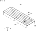
- Fig. 7 is a perspective view which shows an upper frame and a lower frame included in the battery module of Fig. 3 .
- Fig. 8 is a view showing a state in which the upper frame of Fig. 7 is reversed so that the lower surface of the bottom part can be seen.
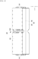
- Fig. 9 is a cross-sectional view showing a cross section taken along the cutting line A-A' of Fig. 1 .
- Fig. 10 is a partial view which enlarges and shows a section "C" of Fig. 9 .
- the module frame 300 may include an upper frame 400 and a lower frame 500, wherein a cooling flow path P may be formed between the upper frame 400 and the lower frame 500.
- the inlet port 810 for supplying the refrigerant to the cooling flow path P and the outlet port 820 for discharging the refrigerant from the cooling flow path P are located opposite to each other, so that the refrigerant flows in one direction in the cooling flow path P.
- the longitudinal direction d1 of the battery cell 110 is in parallel with the one direction in which the refrigerant flows on the basis of the battery cell 110. More specifically, the refrigerant may flow in a straight line in the cooling flow path P. As shown in Fig. 7 , the refrigerant may flow in a straight line in a direction parallel to the x-axis in the cooling flow path P.
- the upper frame 400 may include a bottom part 410 on which the upper battery cell stack 200U is placed and a side surface parts 420 extending upward from opposite sides of the bottom part 410.
- the bottom part 410 and the side surface parts 420 may cover the lower surface and both side surfaces of the upper battery cell stack 200U, respectively.
- the lower frame 500 may include a ceiling part 510 located above the lower battery cell stack 200L and side surface parts 520 extending downward from opposite sides of the ceiling part 510.
- the upper surface and both side surfaces of the lower battery cell stack 200L may be covered by the ceiling part 510 and the side surface parts 520, respectively.
- the upper frame 400 may include an upper plate 411 that is located on the lower surface of the bottom part 410 of the upper frame 400 and an upper recessed part 412 that is recessed upward from the upper plate 411.
- Fig. 8 is a state in which the upper frame 400 is reversed so that the lower surface of the bottom part 410 can be seen, wherein the upper plate 411 is structured to protrude relatively in the -z-axis direction, and the upper recessed part 412 is structured to be relatively recessed in the z-axis direction.
- the method of forming the upper plate 411 and the upper recessed part 412 is not particularly limited.
- a partial region of the plate-shaped member can be recessed upward to form the upper plate 411 and the upper recessed part 412.
- the protruding member can be joined to the lower surface of the plate-shaped member to form the upper plate 411 and the upper recessed part 412.
- the lower frame 500 may include a lower plate 511 that is located on the upper surface of the ceiling part 510 of the lower frame 500 and a lower recessed part 512 that is recessed downward from the lower plate 511.
- the lower plate 511 is structured to protrude relatively in the z-axis direction
- the lower recessed part 512 is structured to be relatively recessed in the -z-axis direction.
- the method of forming the lower plate 511 and the lower recessed part 512 is not particularly limited.
- a partial region of the plate-shaped member can be recessed downward to form the lower plate 511 and the lower recessed part 512.
- the protruding member can be joined to the upper surface of the plate-shaped member to form the lower plate 511 and the lower recessed part 512.
- the upper plate 411 and the lower plate 511 can be joined, and the upper recessed part 412 and the lower recessed part 512 corresponding to each other can form the cooling flow path P.
- the upper plate 411 and the lower plate 511 may extend in parallel with the longitudinal direction d1 of the battery cell 110. Thereby, the refrigerant may flow in one direction through the upper recessed part 412 and the lower recessed part 512 in the cooling flow path P.
- the cooling flow path P formed in the battery module 100 according to the present embodiment extends along one direction instead of the bent path. Also, it is in parallel with the longitudinal direction d1 of the battery cell 110. Uniform cooling for each of the plurality of battery cells 110 may be possible for the upper battery cell stack 200U or the lower battery cell stack 200L. Since the temperature deviation between the battery cells 110 included in the battery module 100 leads to deterioration of battery performance, it is important to eliminate the temperature deviation. Since the battery module 100 according to the present embodiment enables uniform cooling of each battery cell 110, a temperature deviation between respective battery cells 110 can be reduced.
- the straight-line cooling flow path P can reduce pressure drop in the latter half of the cooling flow path P, compared to the paths curved in plural numbers.
- a cooling flow path having the paths curved in plural numbers particularly, a cooling flow path in which the inlet port and the outlet port of the refrigerant are located on the same side and which essentially includes a large bent path, the pressure loss of the refrigerant is large, and thus, a large-capacity refrigerant pump is required for supplying and discharging the refrigerant. Since such a large-capacity refrigerant pump occupies a large space, the space efficiency inside a device such as an automobile is deteriorated.
- the cooling flow path P according to the present embodiment is a path that extends along one direction, and pressure drop can be greatly reduced. Thereby, equivalent heat exchange performance and cooling performance can be realized even with a smaller capacity refrigerant pump. Since a refrigerant pump having a smaller capacity can be used, there is an advantage in that the space inside a device such as an automobile can be efficiently utilized.
- the upper battery cell stack 200U and the lower battery cell stack 200L have a structure stacked in two stages, and a cooling flow path P is formed therebetween. That is, the upper battery cell stack 200U and the lower battery cell stack 200L have a shape of sharing one cooling flow path P, rather than having separate cooling flow paths. As compared to forming a separate cooling path, the number of parts required for cooling can be reduced, and as the number of parts is reduced, the assembling property of the battery module can be improved. Further, since one cooling flow path P is shared, the space utilization inside the battery module 100 can be increased.
- an upper thermal resin layer may be located between the upper battery cell stack 200U and the bottom part 410 of the upper frame 400.
- a lower thermal resin layer may be located between the lower battery cell stack 200L and the ceiling part 510 of the lower frame 500.
- the upper and lower thermal resin layers can be formed by applying a thermal resin having high thermal conductivity and adhesiveness and then curing it.
- the thermal resin may include at least one of a silicone material, a urethane material, or an acrylic material. Heat generated in the upper battery cell stack 200U may be transferred to the cooling flow path P through the upper thermal resin layer, and heat generated in the lower battery cell stack 200L may be transferred to the cooling flow path P through the lower thermal resin layer.
- Fig. 11 is a perspective view which shows a lower frame according to a modified embodiment of the present disclosure.
- the lower frame 500' may include a ceiling part 510 and a side surface part 520, and may include a lower plate 511' that is located on the upper surface of the ceiling part 510 and a lower recessed part 512' that is recessed downward from the lower plate 511'.
- the cooling flow path P' formed by the lower plate 511' and the lower recessed part 512' may have a curved path while continuing in one direction. Although it is not bent at a level of about 90 degrees, a curved cooling flow path P' having bending to some degree may be formed by the lower plate 511' and the lower recessed part 512'.
- the refrigerant may flow in a curved line along one direction in the cooling flow path P'.
- the upper plate and the upper recessed part of the upper frame may also form a curved cooling flow path so as to correspond to the lower plate 511' and the lower recessed part 512'.
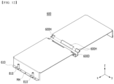
- Fig. 12 is a perspective view which shows an upper cover included in the battery module of Fig. 3 .
- Fig. 13 is a perspective view which shows a lower cover included in the battery module of Fig. 3 .
- the battery module 100 may further include an upper cover 600 for covering the opened portion of the upper frame 400 and a lower cover 700 for covering the opened portion of the lower frame 500.
- the upper cover 600 may cover the front surface and the upper surface of the first upper battery cell stack 210U, and the rear surface and the upper surface of the second upper battery cell stack 220U.
- the front surface and the upper surface of the first upper battery cell stack 210U mean a surface in the x-axis direction and a surface in the z-axis direction of the first upper battery cell stack 210U.
- the rear surface and the upper surface of the second upper battery cell stack 220U mean a surface in the - x-axis direction and a surface in the z-axis direction of the second upper battery cell stack 220U.
- the upper cover 600 and the upper frame 400 are joined to their corresponding edges, so that the upper battery cell stack 200U can be housed therein.
- the lower cover 700 may cover the front and lower surfaces of the first lower battery cell stack 210L, and the rear and lower surfaces of the second lower battery cell stack 220L.
- the front surface and the lower surface of the first lower battery cell stack 210L mean a surface in the x-axis direction and a surface in the -z-axis direction of the first lower battery cell stack 210L.
- the rear surface and the lower surface of the second lower battery cell stack 220L mean a surface in the -x-axis direction and a surface in the -z-axis direction of the second lower battery cell stack 220L.
- the lower cover 700 and the lower frame 500 are joined to their corresponding edges, so that the lower battery cell stack 200L can be housed therein.
- the upper cover 600 may include an upper recessed part 600D that is recessed downward between the first upper battery cell stack 210U and the second upper battery cell stack 220U.
- the first upper battery cell stack 210U and the second upper battery cell stack 220U may be spatially separated by the upper recessed part 600D.
- the lower cover 700 may include a lower recessed part 700D that is recessed upward between the first lower battery cell stack 210L and the second lower battery cell stack 220L.
- the first lower battery cell stack 210L and the second lower battery cell stack 220L may be spatially separated by the lower recessed part 700D.
- the first upper battery cell stack 210U and the second upper battery cell stack 220U may include an electrode terminal ET and a module connector MT, respectively.
- the electrode terminal ET and the module connector MT may be mounted on a busbar frame located on one surface of each battery cell stack.
- the electrode terminal ET may be electrically connected to any one of the electrode leads 111 and 112 (see Fig. 6 ) of the battery cell 110.
- the electrode terminal ET is exposed to the outside of the battery module 100, wherein the battery module 100 is connected to another battery module, BDU (battery disconnect unit) or the like via the electrode terminal ET, thereby capable of realizing HV (High Voltage) connection.
- the HV connection is a connection that serves as a power source for supplying power, and means a connection between battery cells or a connection between battery modules.
- the module connector MT may be electrically connected to any one of the electrode leads 111 and 112 (see Fig. 6 ) of the battery cell 110.
- the module connector MT is exposed to the outside of the battery module 100, wherein the voltage information or temperature level of the battery cell 110 is transferred to the BMS (battery management system) via the module connector (MT), thereby capable of realizing LV (low voltage) connection.
- the LV connection means a sensing connection that senses and controls the voltage and temperature information of the battery cell.
- each of the first upper battery cell stack 210U and the second upper battery cell stack 220U may include an electrode terminal ET and a module connector MT that are exposed toward the upper recessed part 600D of the upper cover 600.
- the upper cover 600 may be formed with an upper opening 600H through which the electrode terminal ET and the module connector MT of each of the first upper battery cell stack 210U and the second upper battery cell stack 220U can be exposed, wherein the upper opening 600H may be opened toward the upper recessed part 600D.
- each of the first lower battery cell stack 210L and the second lower battery cell stack 220L may include an electrode terminal and a module connector that are exposed toward the lower recessed part 700D of the lower cover 700.
- the lower cover 700 may be formed with a lower opening 700H through which electrode terminals and module connectors of the first lower battery cell stack 210L and the second lower battery cell stack 220L can be exposed, wherein the lower opening 700H may be opened toward the lower recessed part 700D.
- a high voltage (HV) connection for connecting the electrode terminals ET and a low voltage (LV) connection for connecting the module connector MT are formed in each of the upper recessed part 600D and the lower recessed part 700D. Specifically, it will be described with reference to Fig. 14 .
- Fig. 14 is a plan view which shows a battery pack according to an embodiment of the present disclosure.
- the battery pack 1000 may include a plurality of battery modules 100.
- the plurality of battery modules 100 are arranged so that the side surfaces are in contact with each other, and can be housed in the pack frame 1100.
- the electrode terminals ET exposed through the upper openings 600H of the upper recessed part 600D may be connected to each other through a connection member to form an HV connection.
- the module connectors MT exposed through the upper openings 600H of the upper recessed part 600D may be connected to each other through a connecting member to form an LV connection. As described above, it can eventually be connected to a BMS (battery management system).
- BMS battery management system
- HV connection and LV connection can be made in the upper recessed part 600D of the upper battery cell stack 200U. Meanwhile, although not specifically shown in the figure, HV connection and LV connection between the lower battery cell stacks 200L may be made similarly to the above in the lower recessed part 700D.
- an upper recessed part 600D that spatially separates the first upper battery cell stack 210U and the second upper battery cell stack 220U is formed, and HV connection and LV connection are made to the upper recessed part 600D.
- a lower recessed part 700D that spatially separates the first lower battery cell stack 210L and the second lower battery cell stack 220L is formed, and HV connection and LV connection are made to the lower recessed part 700D.
- a mounting hole MH for mounting coupling may be formed in each of the upper recessed part 600D and the lower recessed part 700D.
- the mounting hole MH of the upper recessed part 600D and the mounting hole MH of the lower recessed part 700D may be located so as to correspond to each other.
- holes may be formed in the upper plate 411 of the upper frame 400 and the lower plate 511 of the lower frame 500 so as to correspond to the mounting holes MH of the upper recessed part 600D and the lower recessed part 700D.
- the upper cover 600, the upper frame 400, the lower frame 500 and the lower cover 700 can be fixed to each other and at the same time, the battery module 100 can be fixed to the pack frame 1100.
- the fixing method through the mounting hole MH is not particularly limited, and as an example, a bolt and nut coupling can be used.
- the upper recessed part 600D and the lower recessed part 700D according to the present embodiment can not only provide a space for HV connection and LV connection, but also perform the function of fixing the mounting of the battery module 100 .
- the upper cover 600 may include a first upper protrusion part 610 located on one side and a second upper protrusion part 620 located on the other side opposite to the one side.
- An inlet port 810 may be located in the first upper protrusion part 610, and an outlet port 820 may be located in the second upper protrusion part 620. As described above, the inlet port 810 for supplying the refrigerant to the cooling flow path P and the outlet port 820 for discharging the refrigerant from the cooling flow path P may be located opposite to each other. The refrigerant inflowed through the inlet port 810 may flow along the cooling flow path P in one direction and then be discharged through the outlet port 820.
- the lower cover 700 may include a first lower protrusion part 710 located so as to correspond to the first upper protrusion part 610 and a second lower protrusion part 720 located so as to correspond to the second upper protrusion part 620.
- a mounting hole MH for mounting coupling may be formed in each of the first upper protrusion part 610 and the first lower protrusion part 710.
- the mounting hole MH of the first upper protrusion part 610 and the mounting hole MH of the first lower protrusion part 710 may be located so as to correspond to each other.
- a mounting hole for mounting coupling may be formed in each of the second upper protrusion part 620 and the second lower protrusion part 720.
- the mounting hole MH of the second upper protrusion part 620 and the mounting hole MH of the second lower protrusion part 720 may be located so as to correspond to each other.
- the first upper protrusion part 610 and the first lower protrusion part 710 may be coupled to each other through the mounting hole MH.
- the battery module 100 may be fixed to the pack frame 1100 through the mounting holes MH of the first upper protrusion part 610 and the first lower protrusion part 710.
- the second upper protrusion part 620 and the second lower protrusion part 720 may be coupled to each other through the mounting hole MH.
- the battery module 100 may be fixed to the pack frame 1100 through the mounting holes MH of the second upper protrusion part 620 and the second lower protrusion part 720.
- the first upper protrusion part 610 provided with the inlet port 810 is mount-coupled to the first lower protrusion part 710, it is possible to reduce the possibility of leakage of the refrigerant through the gap between the first upper protrusion part 610 and the first lower protrusion part 710. That is, the pressing force of the mounting coupling can be used as a sealing force for preventing leakage in the process of inflowing the refrigerant.
- the second upper protrusion part 620 provided with the outlet port 820 is mount-coupled to the second lower protrusion part 720, it is possible to reduce the possibility of leakage of the refrigerant through the gap between the second upper protrusion part 620 and the second lower protrusion part 720. That is, the pressing force of the mounting coupling can be used as a sealing force for preventing leakage in the discharge process of the refrigerant.
- the one or more battery modules according to embodiments of the present disclosure described above can be mounted together with various control and protection systems such as a BMS(battery management system), a BDU(battery disconnect unit), and a cooling system to form a battery pack.
- BMS battery management system
- BDU battery disconnect unit
- the battery module or the battery pack can be applied to various devices.
- vehicle means such as an electric bike, an electric vehicle, and a hybrid electric vehicle, and may be applied to various devices capable of using a secondary battery, without being limited thereto.
Landscapes
- Chemical & Material Sciences (AREA)
- Chemical Kinetics & Catalysis (AREA)
- Electrochemistry (AREA)
- General Chemical & Material Sciences (AREA)
- Engineering & Computer Science (AREA)
- Manufacturing & Machinery (AREA)
- Secondary Cells (AREA)
- Battery Mounting, Suspending (AREA)
Applications Claiming Priority (2)
| Application Number | Priority Date | Filing Date | Title |
|---|---|---|---|
| KR1020210036923A KR102892943B1 (ko) | 2021-03-22 | 2021-03-22 | 전지 모듈 및 이를 포함하는 전지팩 |
| PCT/KR2022/002995 WO2022203232A1 (fr) | 2021-03-22 | 2022-03-03 | Module de batterie et bloc-batterie le comprenant |
Publications (3)
| Publication Number | Publication Date |
|---|---|
| EP4210152A1 true EP4210152A1 (fr) | 2023-07-12 |
| EP4210152A4 EP4210152A4 (fr) | 2024-05-01 |
| EP4210152B1 EP4210152B1 (fr) | 2025-07-23 |
Family
ID=83397563
Family Applications (1)
| Application Number | Title | Priority Date | Filing Date |
|---|---|---|---|
| EP22775934.7A Active EP4210152B1 (fr) | 2021-03-22 | 2022-03-03 | Module de batterie et bloc-batterie le comprenant |
Country Status (9)
| Country | Link |
|---|---|
| US (3) | US12542313B2 (fr) |
| EP (1) | EP4210152B1 (fr) |
| JP (2) | JP7633393B2 (fr) |
| KR (3) | KR102892943B1 (fr) |
| CN (1) | CN116457983A (fr) |
| ES (1) | ES3049555T3 (fr) |
| HU (1) | HUE073423T2 (fr) |
| PL (1) | PL4210152T3 (fr) |
| WO (1) | WO2022203232A1 (fr) |
Families Citing this family (8)
| Publication number | Priority date | Publication date | Assignee | Title |
|---|---|---|---|---|
| KR102851447B1 (ko) * | 2022-11-16 | 2025-08-26 | 주식회사 엘지에너지솔루션 | 전지 모듈 및 이를 포함하는 전지 팩 |
| KR20240077122A (ko) | 2022-11-24 | 2024-05-31 | 에스케이온 주식회사 | 배터리 팩 |
| US20250343294A1 (en) * | 2022-12-19 | 2025-11-06 | Lg Energy Solution, Ltd. | Double-Sided Cooling Type Battery Module and Heat Sink Included Therein |
| USD1095406S1 (en) * | 2023-04-19 | 2025-09-30 | Sungrow Power Supply Co., Ltd. | Battery pack |
| KR20250128005A (ko) * | 2024-02-20 | 2025-08-27 | 주식회사 엘지에너지솔루션 | 전지 모듈 및 이를 포함하는 전지팩 |
| KR20250134370A (ko) * | 2024-03-04 | 2025-09-11 | 주식회사 엘지에너지솔루션 | 배터리 팩 |
| WO2025192922A1 (fr) * | 2024-03-15 | 2025-09-18 | 주식회사 엘지에너지솔루션 | Bloc-batterie, couvercle de bloc et véhicule les comprenant |
| US12531305B2 (en) * | 2024-06-20 | 2026-01-20 | Estes Energy Solutions, Inc. | Thermo-structural battery packs and systems |
Family Cites Families (30)
| Publication number | Priority date | Publication date | Assignee | Title |
|---|---|---|---|---|
| JP2008165989A (ja) * | 2006-12-27 | 2008-07-17 | Calsonic Kansei Corp | 車両用バッテリ冷却システム |
| KR101156527B1 (ko) | 2010-06-01 | 2012-06-21 | 에스비리모티브 주식회사 | 전지팩 |
| JP5556491B2 (ja) | 2010-08-06 | 2014-07-23 | 株式会社豊田自動織機 | バッテリパック |
| KR101847182B1 (ko) | 2011-07-07 | 2018-04-10 | 에스케이이노베이션 주식회사 | 수냉식 냉각을 위한 열전도성 케이스를 가지는 배터리 |
| KR101588251B1 (ko) * | 2013-06-11 | 2016-01-25 | 주식회사 엘지화학 | 냉매 및 배기 가스의 혼합을 방지하는 구조를 포함하는 전지모듈 |
| KR101608853B1 (ko) * | 2013-06-20 | 2016-04-04 | 주식회사 엘지화학 | 이차 전지용 프레임 및 이를 포함하는 배터리 모듈 |
| KR101609232B1 (ko) * | 2013-08-28 | 2016-04-05 | 주식회사 엘지화학 | 냉매 유로가 형성된 카트리지를 포함하는 전지모듈 |
| KR101579483B1 (ko) | 2014-02-25 | 2015-12-22 | 엘지전자 주식회사 | 배터리팩 |
| KR101779944B1 (ko) * | 2014-08-29 | 2017-09-19 | 주식회사 엘지화학 | 콤팩트하고 안정성이 우수한 냉각부재와 이를 포함하는 전지모듈 |
| JP2016201303A (ja) | 2015-04-13 | 2016-12-01 | ダイキョーニシカワ株式会社 | 発熱体の温度調節構造 |
| KR102072220B1 (ko) | 2016-01-12 | 2020-01-31 | 주식회사 엘지화학 | 디바이스에 대한 탑재 공간이 최소화된 전지팩 |
| KR102731553B1 (ko) * | 2016-12-15 | 2024-11-18 | 현대자동차주식회사 | 냉각 구조가 구비된 배터리 모듈 |
| KR102319537B1 (ko) * | 2017-12-20 | 2021-10-29 | 주식회사 엘지에너지솔루션 | 배터리 모듈, 이를 포함하는 배터리 팩 및 자동차 |
| KR102273195B1 (ko) * | 2017-12-27 | 2021-07-05 | 주식회사 엘지에너지솔루션 | 개선된 냉각 구조를 갖는 배터리 모듈 |
| KR102391984B1 (ko) | 2018-05-23 | 2022-04-27 | 주식회사 엘지에너지솔루션 | 전지 모듈용 냉각 부재 및 이를 포함하는 전지팩 |
| CN109119552A (zh) | 2018-08-26 | 2019-01-01 | 杭州捷能科技有限公司 | 一种轻量化高效电池包 |
| JP6683779B2 (ja) | 2018-08-31 | 2020-04-22 | 本田技研工業株式会社 | バッテリパックの冷却構造 |
| KR102640328B1 (ko) | 2018-10-19 | 2024-02-22 | 삼성에스디아이 주식회사 | 배터리의 대형 모듈 |
| KR102640329B1 (ko) | 2018-10-19 | 2024-02-22 | 삼성에스디아이 주식회사 | 배터리 모듈 |
| JP6713524B2 (ja) * | 2018-12-17 | 2020-06-24 | 本田技研工業株式会社 | バッテリユニット |
| US12230820B2 (en) | 2019-01-09 | 2025-02-18 | Byd Company Limited | Power battery pack and electric vehicle |
| US20200251698A1 (en) | 2019-01-31 | 2020-08-06 | Ford Global Technologies, Llc | Multi-tiered battery pack and liquid coolant communication method for same |
| CN209843767U (zh) | 2019-03-28 | 2019-12-24 | 蜂巢能源科技有限公司 | 模组支架及电池包 |
| KR102872962B1 (ko) * | 2019-05-16 | 2025-10-20 | 현대자동차주식회사 | 차량용 배터리 냉각 시스템 |
| KR102846780B1 (ko) * | 2019-06-17 | 2025-08-13 | 주식회사 엘지에너지솔루션 | 냉각부재를 구비한 배터리 모듈 및 배터리 팩 및 전력 저장장치 |
| KR102705400B1 (ko) | 2019-08-07 | 2024-09-12 | 주식회사 엘지에너지솔루션 | 자동차용 언더 바디 |
| KR102769904B1 (ko) | 2019-08-07 | 2025-02-17 | 주식회사 엘지에너지솔루션 | 배터리 모듈들의 기계적, 전기적 고정구조를 통합한 배터리 팩 |
| GB2588587B (en) | 2019-10-18 | 2022-09-21 | Dyson Technology Ltd | Battery pack |
| CN111477931A (zh) * | 2020-04-30 | 2020-07-31 | 昆山宝创新能源科技有限公司 | 软包电池和车辆 |
| CN111769221A (zh) | 2020-06-02 | 2020-10-13 | 北京新能源汽车股份有限公司蓝谷动力系统分公司 | 用于车辆的电池模组和车辆 |
-
2021
- 2021-03-22 KR KR1020210036923A patent/KR102892943B1/ko active Active
-
2022
- 2022-03-03 JP JP2023522887A patent/JP7633393B2/ja active Active
- 2022-03-03 EP EP22775934.7A patent/EP4210152B1/fr active Active
- 2022-03-03 ES ES22775934T patent/ES3049555T3/es active Active
- 2022-03-03 PL PL22775934.7T patent/PL4210152T3/pl unknown
- 2022-03-03 US US18/030,477 patent/US12542313B2/en active Active
- 2022-03-03 WO PCT/KR2022/002995 patent/WO2022203232A1/fr not_active Ceased
- 2022-03-03 HU HUE22775934A patent/HUE073423T2/hu unknown
- 2022-03-03 CN CN202280007227.1A patent/CN116457983A/zh active Pending
-
2024
- 2024-10-08 US US18/909,748 patent/US12407042B2/en active Active
- 2024-11-26 KR KR1020240170711A patent/KR102892942B1/ko active Active
-
2025
- 2025-02-05 JP JP2025017655A patent/JP2025074084A/ja active Pending
- 2025-07-24 US US19/279,821 patent/US20260100446A1/en active Pending
- 2025-11-19 KR KR1020250176006A patent/KR20250174845A/ko active Pending
Also Published As
| Publication number | Publication date |
|---|---|
| JP2023546083A (ja) | 2023-11-01 |
| EP4210152A4 (fr) | 2024-05-01 |
| US12407042B2 (en) | 2025-09-02 |
| KR20250174845A (ko) | 2025-12-15 |
| US20230378568A1 (en) | 2023-11-23 |
| KR20220131782A (ko) | 2022-09-29 |
| EP4210152B1 (fr) | 2025-07-23 |
| US12542313B2 (en) | 2026-02-03 |
| KR102892942B1 (ko) | 2025-11-27 |
| WO2022203232A1 (fr) | 2022-09-29 |
| US20250038304A1 (en) | 2025-01-30 |
| KR20240170515A (ko) | 2024-12-03 |
| US20260100446A1 (en) | 2026-04-09 |
| PL4210152T3 (pl) | 2025-11-12 |
| KR102892943B1 (ko) | 2025-11-27 |
| CN116457983A (zh) | 2023-07-18 |
| JP2025074084A (ja) | 2025-05-13 |
| ES3049555T3 (en) | 2025-12-17 |
| HUE073423T2 (hu) | 2026-01-28 |
| JP7633393B2 (ja) | 2025-02-19 |
Similar Documents
| Publication | Publication Date | Title |
|---|---|---|
| EP4210152B1 (fr) | Module de batterie et bloc-batterie le comprenant | |
| EP4199208B1 (fr) | Bloc-batterie | |
| US12327850B2 (en) | Battery module and battery pack including the same | |
| EP4184706B1 (fr) | Module de batterie, bloc-batterie comprenant celui-ci, et son procédé de fabrication | |
| EP4016703A1 (fr) | Module de batterie et bloc-batterie le comprenant | |
| EP4290653B1 (fr) | Bloc-batterie et dispositif le comprenant | |
| CN115336086A (zh) | 电池组和包括该电池组的装置 | |
| EP4228061B1 (fr) | Bloc-batterie et dispositif le comprenant | |
| EP4266457A1 (fr) | Module de batterie et bloc-batterie le comprenant | |
| EP4210154A1 (fr) | Bloc-batterie et dispositif le comprenant | |
| EP4181275B1 (fr) | Module de batterie et bloc-batterie le comprenant | |
| EP4089799A1 (fr) | Module de batterie et bloc-batterie le comprenant | |
| US20250279503A1 (en) | Battery module and battery pack including the same | |
| US20240113357A1 (en) | Battery pack and device including the same | |
| EP4181286B1 (fr) | Module de batterie et bloc-batterie le comprenant | |
| EP4300661B1 (fr) | Module de batterie et batterie le comprenant |
Legal Events
| Date | Code | Title | Description |
|---|---|---|---|
| STAA | Information on the status of an ep patent application or granted ep patent |
Free format text: STATUS: THE INTERNATIONAL PUBLICATION HAS BEEN MADE |
|
| PUAI | Public reference made under article 153(3) epc to a published international application that has entered the european phase |
Free format text: ORIGINAL CODE: 0009012 |
|
| STAA | Information on the status of an ep patent application or granted ep patent |
Free format text: STATUS: REQUEST FOR EXAMINATION WAS MADE |
|
| 17P | Request for examination filed |
Effective date: 20230403 |
|
| AK | Designated contracting states |
Kind code of ref document: A1 Designated state(s): AL AT BE BG CH CY CZ DE DK EE ES FI FR GB GR HR HU IE IS IT LI LT LU LV MC MK MT NL NO PL PT RO RS SE SI SK SM TR |
|
| A4 | Supplementary search report drawn up and despatched |
Effective date: 20240402 |
|
| RIC1 | Information provided on ipc code assigned before grant |
Ipc: H01M 50/296 20210101ALI20240325BHEP Ipc: H01M 50/271 20210101ALI20240325BHEP Ipc: H01M 50/209 20210101ALI20240325BHEP Ipc: H01M 10/625 20140101ALI20240325BHEP Ipc: H01M 10/6567 20140101ALI20240325BHEP Ipc: H01M 10/647 20140101ALI20240325BHEP Ipc: H01M 10/42 20060101ALI20240325BHEP Ipc: H01M 50/211 20210101ALI20240325BHEP Ipc: H01M 10/613 20140101ALI20240325BHEP Ipc: H01M 10/6556 20140101AFI20240325BHEP |
|
| DAV | Request for validation of the european patent (deleted) | ||
| DAX | Request for extension of the european patent (deleted) | ||
| GRAP | Despatch of communication of intention to grant a patent |
Free format text: ORIGINAL CODE: EPIDOSNIGR1 |
|
| STAA | Information on the status of an ep patent application or granted ep patent |
Free format text: STATUS: GRANT OF PATENT IS INTENDED |
|
| RIC1 | Information provided on ipc code assigned before grant |
Ipc: H01M 50/204 20210101ALI20250408BHEP Ipc: H01M 10/6568 20140101ALI20250408BHEP Ipc: H01M 10/6554 20140101ALI20250408BHEP Ipc: H01M 10/613 20140101ALI20250408BHEP Ipc: H01M 50/211 20210101ALI20250408BHEP Ipc: H01M 10/42 20060101ALI20250408BHEP Ipc: H01M 10/647 20140101ALI20250408BHEP Ipc: H01M 10/6567 20140101ALI20250408BHEP Ipc: H01M 10/625 20140101ALI20250408BHEP Ipc: H01M 50/209 20210101ALI20250408BHEP Ipc: H01M 50/271 20210101ALI20250408BHEP Ipc: H01M 50/296 20210101ALI20250408BHEP Ipc: H01M 10/6556 20140101AFI20250408BHEP |
|
| INTG | Intention to grant announced |
Effective date: 20250423 |
|
| GRAS | Grant fee paid |
Free format text: ORIGINAL CODE: EPIDOSNIGR3 |
|
| GRAA | (expected) grant |
Free format text: ORIGINAL CODE: 0009210 |
|
| STAA | Information on the status of an ep patent application or granted ep patent |
Free format text: STATUS: THE PATENT HAS BEEN GRANTED |
|
| P01 | Opt-out of the competence of the unified patent court (upc) registered |
Free format text: CASE NUMBER: APP_24175/2025 Effective date: 20250521 |
|
| AK | Designated contracting states |
Kind code of ref document: B1 Designated state(s): AL AT BE BG CH CY CZ DE DK EE ES FI FR GB GR HR HU IE IS IT LI LT LU LV MC MK MT NL NO PL PT RO RS SE SI SK SM TR |
|
| REG | Reference to a national code |
Ref country code: GB Ref legal event code: FG4D |
|
| REG | Reference to a national code |
Ref country code: CH Ref legal event code: EP |
|
| REG | Reference to a national code |
Ref country code: DE Ref legal event code: R096 Ref document number: 602022018144 Country of ref document: DE |
|
| REG | Reference to a national code |
Ref country code: IE Ref legal event code: FG4D |
|
| REG | Reference to a national code |
Ref country code: NL Ref legal event code: FP |
|
| REG | Reference to a national code |
Ref country code: SE Ref legal event code: TRGR |
|
| PG25 | Lapsed in a contracting state [announced via postgrant information from national office to epo] |
Ref country code: PT Free format text: LAPSE BECAUSE OF FAILURE TO SUBMIT A TRANSLATION OF THE DESCRIPTION OR TO PAY THE FEE WITHIN THE PRESCRIBED TIME-LIMIT Effective date: 20251124 |
|
| REG | Reference to a national code |
Ref country code: AT Ref legal event code: MK05 Ref document number: 1817404 Country of ref document: AT Kind code of ref document: T Effective date: 20250723 |
|
| REG | Reference to a national code |
Ref country code: ES Ref legal event code: FG2A Ref document number: 3049555 Country of ref document: ES Kind code of ref document: T3 Effective date: 20251217 |
|
| PG25 | Lapsed in a contracting state [announced via postgrant information from national office to epo] |
Ref country code: IS Free format text: LAPSE BECAUSE OF FAILURE TO SUBMIT A TRANSLATION OF THE DESCRIPTION OR TO PAY THE FEE WITHIN THE PRESCRIBED TIME-LIMIT Effective date: 20251123 |
|
| PG25 | Lapsed in a contracting state [announced via postgrant information from national office to epo] |
Ref country code: NO Free format text: LAPSE BECAUSE OF FAILURE TO SUBMIT A TRANSLATION OF THE DESCRIPTION OR TO PAY THE FEE WITHIN THE PRESCRIBED TIME-LIMIT Effective date: 20251023 |
|
| REG | Reference to a national code |
Ref country code: LT Ref legal event code: MG9D |
|
| PG25 | Lapsed in a contracting state [announced via postgrant information from national office to epo] |
Ref country code: AT Free format text: LAPSE BECAUSE OF FAILURE TO SUBMIT A TRANSLATION OF THE DESCRIPTION OR TO PAY THE FEE WITHIN THE PRESCRIBED TIME-LIMIT Effective date: 20250723 |
|
| PG25 | Lapsed in a contracting state [announced via postgrant information from national office to epo] |
Ref country code: FI Free format text: LAPSE BECAUSE OF FAILURE TO SUBMIT A TRANSLATION OF THE DESCRIPTION OR TO PAY THE FEE WITHIN THE PRESCRIBED TIME-LIMIT Effective date: 20250723 |
|
| PG25 | Lapsed in a contracting state [announced via postgrant information from national office to epo] |
Ref country code: HR Free format text: LAPSE BECAUSE OF FAILURE TO SUBMIT A TRANSLATION OF THE DESCRIPTION OR TO PAY THE FEE WITHIN THE PRESCRIBED TIME-LIMIT Effective date: 20250723 |
|
| PG25 | Lapsed in a contracting state [announced via postgrant information from national office to epo] |
Ref country code: GR Free format text: LAPSE BECAUSE OF FAILURE TO SUBMIT A TRANSLATION OF THE DESCRIPTION OR TO PAY THE FEE WITHIN THE PRESCRIBED TIME-LIMIT Effective date: 20251024 |
|
| PG25 | Lapsed in a contracting state [announced via postgrant information from national office to epo] |
Ref country code: LV Free format text: LAPSE BECAUSE OF FAILURE TO SUBMIT A TRANSLATION OF THE DESCRIPTION OR TO PAY THE FEE WITHIN THE PRESCRIBED TIME-LIMIT Effective date: 20250723 |
|
| PG25 | Lapsed in a contracting state [announced via postgrant information from national office to epo] |
Ref country code: BG Free format text: LAPSE BECAUSE OF FAILURE TO SUBMIT A TRANSLATION OF THE DESCRIPTION OR TO PAY THE FEE WITHIN THE PRESCRIBED TIME-LIMIT Effective date: 20250723 |
|
| PG25 | Lapsed in a contracting state [announced via postgrant information from national office to epo] |
Ref country code: RS Free format text: LAPSE BECAUSE OF FAILURE TO SUBMIT A TRANSLATION OF THE DESCRIPTION OR TO PAY THE FEE WITHIN THE PRESCRIBED TIME-LIMIT Effective date: 20251023 |
|
| REG | Reference to a national code |
Ref country code: HU Ref legal event code: AG4A Ref document number: E073423 Country of ref document: HU |
|
| PGFP | Annual fee paid to national office [announced via postgrant information from national office to epo] |
Ref country code: NL Payment date: 20260220 Year of fee payment: 5 |
|
| PG25 | Lapsed in a contracting state [announced via postgrant information from national office to epo] |
Ref country code: SM Free format text: LAPSE BECAUSE OF FAILURE TO SUBMIT A TRANSLATION OF THE DESCRIPTION OR TO PAY THE FEE WITHIN THE PRESCRIBED TIME-LIMIT Effective date: 20250723 |
|
| PGFP | Annual fee paid to national office [announced via postgrant information from national office to epo] |
Ref country code: SE Payment date: 20260223 Year of fee payment: 5 |
|
| PGFP | Annual fee paid to national office [announced via postgrant information from national office to epo] |
Ref country code: GB Payment date: 20260224 Year of fee payment: 5 |
|
| PG25 | Lapsed in a contracting state [announced via postgrant information from national office to epo] |
Ref country code: DK Free format text: LAPSE BECAUSE OF FAILURE TO SUBMIT A TRANSLATION OF THE DESCRIPTION OR TO PAY THE FEE WITHIN THE PRESCRIBED TIME-LIMIT Effective date: 20250723 |
|
| PGFP | Annual fee paid to national office [announced via postgrant information from national office to epo] |
Ref country code: DE Payment date: 20260220 Year of fee payment: 5 |
|
| PGFP | Annual fee paid to national office [announced via postgrant information from national office to epo] |
Ref country code: BE Payment date: 20260220 Year of fee payment: 5 Ref country code: IT Payment date: 20260223 Year of fee payment: 5 |
|
| PGFP | Annual fee paid to national office [announced via postgrant information from national office to epo] |
Ref country code: HU Payment date: 20260310 Year of fee payment: 5 |
|
| PGFP | Annual fee paid to national office [announced via postgrant information from national office to epo] |
Ref country code: FR Payment date: 20260224 Year of fee payment: 5 |
|
| PGFP | Annual fee paid to national office [announced via postgrant information from national office to epo] |
Ref country code: TR Payment date: 20260226 Year of fee payment: 5 |
|
| PG25 | Lapsed in a contracting state [announced via postgrant information from national office to epo] |
Ref country code: CZ Free format text: LAPSE BECAUSE OF FAILURE TO SUBMIT A TRANSLATION OF THE DESCRIPTION OR TO PAY THE FEE WITHIN THE PRESCRIBED TIME-LIMIT Effective date: 20250723 |
|
| PGFP | Annual fee paid to national office [announced via postgrant information from national office to epo] |
Ref country code: PL Payment date: 20260223 Year of fee payment: 5 |
|
| PG25 | Lapsed in a contracting state [announced via postgrant information from national office to epo] |
Ref country code: EE Free format text: LAPSE BECAUSE OF FAILURE TO SUBMIT A TRANSLATION OF THE DESCRIPTION OR TO PAY THE FEE WITHIN THE PRESCRIBED TIME-LIMIT Effective date: 20250723 Ref country code: SK Free format text: LAPSE BECAUSE OF FAILURE TO SUBMIT A TRANSLATION OF THE DESCRIPTION OR TO PAY THE FEE WITHIN THE PRESCRIBED TIME-LIMIT Effective date: 20250723 |