EP4210904B1 - Outil d'usinage et procédé - Google Patents
Outil d'usinage et procédé Download PDFInfo
- Publication number
- EP4210904B1 EP4210904B1 EP21773364.1A EP21773364A EP4210904B1 EP 4210904 B1 EP4210904 B1 EP 4210904B1 EP 21773364 A EP21773364 A EP 21773364A EP 4210904 B1 EP4210904 B1 EP 4210904B1
- Authority
- EP
- European Patent Office
- Prior art keywords
- rotation
- machining
- shaft
- axis
- machining tool
- Prior art date
- Legal status (The legal status is an assumption and is not a legal conclusion. Google has not performed a legal analysis and makes no representation as to the accuracy of the status listed.)
- Active
Links
Images


Classifications
-
- B—PERFORMING OPERATIONS; TRANSPORTING
- B24—GRINDING; POLISHING
- B24B—MACHINES, DEVICES, OR PROCESSES FOR GRINDING OR POLISHING; DRESSING OR CONDITIONING OF ABRADING SURFACES; FEEDING OF GRINDING, POLISHING, OR LAPPING AGENTS
- B24B45/00—Means for securing grinding wheels on rotary arbors
-
- B—PERFORMING OPERATIONS; TRANSPORTING
- B23—MACHINE TOOLS; METAL-WORKING NOT OTHERWISE PROVIDED FOR
- B23C—MILLING
- B23C5/00—Milling-cutters
- B23C5/02—Milling-cutters characterised by the shape of the cutter
- B23C5/10—Shank-type cutters, i.e. with an integral shaft
-
- B—PERFORMING OPERATIONS; TRANSPORTING
- B24—GRINDING; POLISHING
- B24B—MACHINES, DEVICES, OR PROCESSES FOR GRINDING OR POLISHING; DRESSING OR CONDITIONING OF ABRADING SURFACES; FEEDING OF GRINDING, POLISHING, OR LAPPING AGENTS
- B24B47/00—Drives or gearings; Equipment therefor
- B24B47/10—Drives or gearings; Equipment therefor for rotating or reciprocating working-spindles carrying grinding wheels or workpieces
- B24B47/12—Drives or gearings; Equipment therefor for rotating or reciprocating working-spindles carrying grinding wheels or workpieces by mechanical gearing or electric power
-
- B—PERFORMING OPERATIONS; TRANSPORTING
- B24—GRINDING; POLISHING
- B24B—MACHINES, DEVICES, OR PROCESSES FOR GRINDING OR POLISHING; DRESSING OR CONDITIONING OF ABRADING SURFACES; FEEDING OF GRINDING, POLISHING, OR LAPPING AGENTS
- B24B9/00—Machines or devices designed for grinding edges or bevels on work or for removing burrs; Accessories therefor
-
- B—PERFORMING OPERATIONS; TRANSPORTING
- B24—GRINDING; POLISHING
- B24D—TOOLS FOR GRINDING, BUFFING OR SHARPENING
- B24D3/00—Physical features of abrasive bodies, or sheets, e.g. abrasive surfaces of special nature; Abrasive bodies or sheets characterised by their constituents
-
- B—PERFORMING OPERATIONS; TRANSPORTING
- B23—MACHINE TOOLS; METAL-WORKING NOT OTHERWISE PROVIDED FOR
- B23C—MILLING
- B23C2210/00—Details of milling cutters
- B23C2210/02—Connections between the shanks and detachable cutting heads
-
- B—PERFORMING OPERATIONS; TRANSPORTING
- B23—MACHINE TOOLS; METAL-WORKING NOT OTHERWISE PROVIDED FOR
- B23C—MILLING
- B23C2210/00—Details of milling cutters
- B23C2210/08—Side or top views of the cutting edge
- B23C2210/084—Curved cutting edges
-
- B—PERFORMING OPERATIONS; TRANSPORTING
- B23—MACHINE TOOLS; METAL-WORKING NOT OTHERWISE PROVIDED FOR
- B23C—MILLING
- B23C2210/00—Details of milling cutters
- B23C2210/60—Axis of the cutter inclined with respect to the axis of rotation
-
- B—PERFORMING OPERATIONS; TRANSPORTING
- B23—MACHINE TOOLS; METAL-WORKING NOT OTHERWISE PROVIDED FOR
- B23C—MILLING
- B23C2220/00—Details of milling processes
- B23C2220/04—Milling with the axis of the cutter inclined to the surface being machined
Definitions
- the present invention relates to a machining tool comprising a shaft which can be rotated by a motor about a first axis of rotation.
- the machining tool comprises a machining element for machining a surface of a workpiece, such as a surface of a mould.
- the invention further relates to a method of machining a surface.
- part of the plastic material forming the moulded elements may be deposited in the moulds which consequently will have to be cleaned or machined on a regular basis.
- the moulds are cleaned by machining the moulds by use of a machining surface working in one plane, typically in an orbital movement pattern.
- Machining tools of the kind to which the invention pertains are used in different kinds of surface treatment including treatment of moulds.
- Other examples of machining relate to surface machining of tools for metal forming operations. Examples of tools are moulds for deep drawing, punching, sinter pressing, and cold or warm forging, etc.
- the work which is carried out by the polishing or grinding tool typically depends on the position and orientation of the tool relative to the workpiece, and a good result can only be expected by a specific orientation of the tool against the surface of the workpiece.
- JP publication no 10086050 discloses a polishing tool with three polishing pads formed on a bottom face of a polishing head to obtain equal distance and angle in relation to the central axis of the polishing head 2 and the item to be polished.
- the head is attached to a shaft by a universal joint allowing change in inclination of the head by rotation about an axis being perpendicular to the axis of rotation of the shaft. While this structure and particularly the universal joint may allow the head to follow the surface of the item which is polished, it does not produce any polishing movement caused by the rotation about the universal joint.
- a universal joint is a joint or coupling connecting rigid rods whose axes are inclined to each other and is commonly used in shafts that transmit rotary motion from a transmitting, rotating, shaft to receiving shaft being inclined to the transmitting shaft. It consists of a pair of hinges located close together, oriented at 90° to each other, connected by a cross shaft. The effect is simple rotation of the receiving shaft about its axis.
- JP 2002 154040 A discloses a machining tool comprising a motor (implicitly disclosed) and an appliance, the appliance comprising a shaft which is rotatable by the motor about a first axis of rotation, and a machining element having an outer surface forming a contact surface for treatment of a workpiece.
- the invention provides a machining tool as defined in claim 1.
- the appliance comprises a shaft which can be rotated about a first axis of rotation by the motor.
- the machining tool further comprises a machining element forming a contact surface for treatment of a surface of a workpiece.
- the machining element is rotationally attached to the shaft for rotation relative to the shaft about a second axis of rotation, wherein the first axis of rotation and the second axis of rotation form an angle ⁇ , so that the first axis of rotation and the second axis of rotation are not parallel and not perpendicular.
- the angle, ⁇ should be oblique meaning distinct from 0 and 90 degrees. Particularly between 5-85, or 10-80, or 15-75 degrees.
- the feature of the machining element being attached to the shaft for rotation relative to the shaft about a second axis, X2, of rotation means that it can revolve unlimited, i.e., any number of turns, about the second axis, X2.
- the machining element By the combination between rotation of the shaft about the first axis, and rotation of the machining element about second axis being at oblique angle, ⁇ , to the first axis, the machining element creates a nodding movement relative to the shaft.
- the nodding movement is a result of the machining element rotating about the second axis of rotation while the second axis of rotation revolves about the first axis of rotation.
- the ratio between ⁇ 1, ⁇ 2, and ⁇ 3 is changeable. It can be changed e.g., by use of friction between the machining element and the surface which is treated. If the friction between the treated surface and the machining element is sufficiently high, it may reduce ⁇ 3, e.g., to zero. If ⁇ 3 is zero, the motion is a pure nodding motion. If ⁇ 3 is different from zero, the motion may be a combination between nodding motion and rotation.
- Non-limiting examples of machining and treatment of a surface is polishing, grinding, and deburring.
- the machining tool may be configured for abrasive machining, which herein means surface treatment by use of abrasive media and methods.
- the shaft is rotated about the first axis of rotation by the motor.
- the contact surface may particularly be curved since that provides a suitable match with the nodding motion.
- the appliance may e.g., be reversibly detachable from the motor.
- the motor may e.g., form part of a drill, a polisher, or similar rotating power tool, having a rotating spindle onto which the shaft is attached, or the machining tool may include a motor in fixed engagement with the shaft. Since the machining element is attached rotationally to the shaft for rotation about a second axis of rotation, it may freely rotate about the second axis of rotation when the shaft is rotated around the first axis of rotation.
- the shaft constitutes a rotor of an electric motor and thereby form an integrated part of the motor.
- the machining tool can translate rotation of the shaft into oscillating movement of the machining element, i.e. a nodding up and down movement of the machining element relative to the shaft.
- the degree of translation from rotation into the oscillating, nodding, movement can be changed by changing said ratio between ⁇ 1, 2 and 3, and as a result, the machining tool can define a unique movement pattern where force can be directed towards rotation or oscillation depending on the ratio between ⁇ 1, ⁇ 2, and ⁇ 3.
- the unique pattern can be mirrored by reversing the direction of rotation about the first axis of rotation.
- the rotation of the machining element may be stopped by overcoming the friction in the bearing structure between the machining element and the shaft.
- the rotation of the machining element about the first axis of rotation i.e., ⁇ 3
- the force is transferred to the oscillating movement and the machining element will move up and down in the mentioned nodding movement. In this situation, a balance will be established between resistance against rotation and resistance against oscillation.
- the balance depends on the resistance in the bearings which resistance will work towards rotating the machining element, the resistance against rotation of the machining element caused by friction between the machining element and the workpiece, and the resistance against oscillation caused by the friction between the machining element and the workpiece.
- the contact surface can work in all directions with a consistent result, and a universal machining characteristics may thus be provided.
- the outer surface of the machining element forms a curved contact surface, and may particularly form a 3-dimentional curvature, e.g., forming a fraction of a sphere, and that sphere may particularly form a centre point where the first axis of rotation intersects the second axis of rotation.
- the contact surface may oscillate equally in all directions which makes the machining conditions independent on locations and angles of the machining element and the surface which is treated. That facilitates easy and flexible use of the machining tool since the work is independent on orientations or locations of the machining tool relative to the object to be treated.
- sphere an element which is at least substantially spherical, i.e. has circular cross sections within plus or minus 10 percent deviations on a radial dimension from a centre point to the sphere.
- the fraction may be 90% of a sphere, such as 80%, such as 70% or even less than 60% or less than 50 %. In one embodiment, the fraction is far less than 50 pct. Of the sphere, e.g. as little as 20 or 10 %. It the context of the present invention 'a fraction of a sphere' should be understood as a portion of a sphere cut off by a plane; i.e. a part of a sphere where a part has been removed.
- the outer surface may be shaped as a combination of a sphere part and a plane surface part. Particularly, the sphere part may form the contact surface and the plane surface part may face towards the shaft.
- the machining element may be less than 50 % of a sphere and thereby constitute a 3D curved surface rather than a sphere, however, it may still be an aspect to arrange the centre of the sphere in the position where the first and second axis of rotation intersects.
- a counter directed force is created when the machining element contacts a surface of the workpiece.
- the counterforce will typically change the balance of translation and the impact of the counterforce typically exceeds the friction force through the bearings and therefore defines the degree of translation from rotation of the machining element to oscillation of the machining element.
- the outer surface contacts the surface which is to be machined only at the point where the first axis of rotation intersects the outer surface, the moment created by the counter directed force becomes zero, and balance of translation changes.
- the friction through the bearings, and the resistance against oscillation which is mainly caused by the friction between the machining element and the workpiece, may exceed the counter directed force of rotation thereby changing the degree of translation, e.g., to the point where the machining element starts to rotate, and the oscillation fades out.
- the machining tool may comprise a restriction structure configured to apply a braking torque on the machining element, and particularly, an adjustable braking torque.
- the restriction structure may thus control the balance of translation.
- the machining element may be made of copper, brass, steel casting, plastic of various hardness, wood of various hardness, and/or felt or textile of various hardness.
- the motor may be an external motor arranged in communication with the shaft or a motor attached to the shaft.
- the motor may be arranged in a cavity in the shaft or at the shaft.
- the workpiece may as an example be made of steel, tungsten carbide, or ceramics. Machining may be carried out substantially without deforming the machining element when moving the machining element in contact with the surface of the workpiece.
- the machining tool may further comprise a biasing member, such as one or more springs.
- the biasing member may ensure that contact between the machining element and the workpiece is substantially constant and with a substantially even pressure.
- the shaft may comprise a telescopic shaft section allowing for extension of the shaft to thereby enlarge the area which can be machined. If the embodiments where the machining tool is integrated in a numerically controlled machine, the telescopic shaft section may be controlled by the numerically controlled machine. The control may be carried out automatically. In an alternative embodiment, the control of the telescopic shaft section is carried out manually.
- the angle ⁇ is in the range of 2-175 degrees, such as in the range of 10-170 degrees.
- the size of the angle, ⁇ may depend on the size and/or shape of the surface of the workpiece, and/or of the type of material which is deposited on the surface.
- the angle, ⁇ is in the range of 5 ⁇ ⁇ ⁇ 90 degrees, such as in the range of 10-80 degrees.
- the end of the shaft may form a substantially planar surface, and the machining element may be attached to the shaft at that end face.
- the machining element may be attached to the shaft via an interface, which interface may be elongated to form an axle extending along the second axis of rotation, whereby the interface may form an extension to the shaft extending non-parallel to the shaft.
- the interface may extend from the end face of the shaft.
- Rotation of the machining element relative to the shaft about the second axis of rotation may be established in different ways:
- the shaft may be an elongated element, e.g. having the shape of a rod.
- the interface may extend centrally from the end portion of the shaft. In an alternative embodiment, the interface may extend off-set from the centre of the end portion of the shaft.
- Machining, and particularly polishing, grinding, or deburring may be facilitated by use of an abrasive, such as an abrasive paste.
- the abrasive may as an example comprise diamond e.g., in a paste of diamond, silicon carbide, aluminium oxide, and/or cubic boron nitride.
- Abrasive materials may also be used, either alone or in combination with the mentioned examples.
- the machining element may comprise a layer of diamond or CBN, sandpaper for wet or dry sanding, emery cloth, stone etc.
- Compound/Sinter may be used, e.g., metal in combination with an abrasive or rubber in combination with an abrasive.
- At least one flow path may extend through at least a part of the shaft to the machining element.
- the at least one flow path may be arranged for a flow of an abrasive.
- the flow path may be formed as a conduit extending at least partly inside the shaft.
- the flow path may comprise a tube which may be attached to the outer surface of the shaft.
- a part of the flow path may be arranged inside a cavity of the shaft, whereas another part of the flow path may be arranged outside the shaft.
- the at least one flow path may additionally be arranged for a flow of a liquid.
- the liquid flow may be provided to sweep away the abrasive and/or elements being removed from the surface during machining of the workpiece.
- the abrasive and the liquid may be provided through separate flow paths, where one or more first flow paths are arranged for a flow of the abrasive, and where one or more second flow paths are arranged for a flow of liquid.
- first flow paths are arranged for a flow of the abrasive
- second flow paths are arranged for a flow of liquid.
- one or more flow path may be arranged for a flow of an abrasive and flow of liquid.
- the inlet to the flow path can be arranged in communication with a container/box of abrasive and a container/reservoir of liquid. This may be achieved by providing the flow path configured to shift between the abrasive and the liquid.
- Shifting between abrasive and liquid may be done manually or automatically, e.g. in response to a predetermined time schedule where abrasive is provided during a first time period and liquid is provided during a second time period.
- the first and second time periods may be identical.
- a porous material may be arranged in at least one of the at least one openings in the outer surface of the machining element.
- the porous material may slow down the discharge of the abrasive and/or liquid, as the abrasive and/or the liquid may be absorbed in the porous material.
- the machining element may be detachable attached to the machining tool. This may allow for detachment of the machining element for repair or for exchange of the machining element in case of damages. Furthermore, a machining element may be exchanged to a larger or a smaller machining element during use, and/or a machining element with another outer surface characteristic to thereby change the machining ability of the tool.
- a first end of the interface may be attached in an indentation in the machining element.
- the indentation may be arranged at the plane part of the outer surface.
- a frictional bearing may be arranged at least partly in the indentation.
- the shaft may preferably be elongated and may have a length being the dimension along the first axis of rotation and a width being perpendicular to the length. The width may be nonuniform along the length of the shaft.
- the machining element may have a diameter being the dimension of the machining element perpendicular to the second axis of rotation. The diameter may be the largest dimension of the machining element perpendicular to the second axis of rotation in embodiments where the machining element is not shaped substantially as a fraction of a sphere. In one embodiment, the diameter may be at least twice the width of the shaft.
- the length of the shaft may be in the range of 10-500 mm, such as 50-250 mm.
- the machining element may have any size suitable for a specific task.
- the diameter of the machining element may be in the range of 1-200 mm, such as 10-50 mm.
- the length of the shaft and/or the diameter of the machining element in an alternative embodiment may be different.
- the invention provides a method of machining a surface of a workpiece by use of a machining tool according to the first aspect of the invention; the method comprising the steps of;
- the relative rotation of the machining element relative to the shaft around the second axis of rotation may be created by friction by pressing the machining element against a surface to be machined, or it may be created by control of said restriction structure to thereby suppress ⁇ 3.
- the machining element may be moved continuously in different directions in contact with and along the surface to be machined. This may in one embodiment be achieved by integrating the machining tool in a numerically controlled machine. Furthermore, machining may be carried out with the machining element exerting a substantially even pressure at the surface.
- the machining may particularly be polishing, grinding, or deburring, and the surface to be machined may have a first hardness, whereas and the machining element may have a second hardness.
- the first hardness may be different from the second hardness.
- any feature described in combination with the first aspect of the invention could also be combined with the second aspect of the invention, and vice versa, i.e., any of the features of the appliance described relative to the machining tool of the first aspect may apply also for the appliance of the second aspect of the invention.
- the machining tool according to the first aspect of the invention is very suitable for performing the method steps according to the second aspect of the invention.
- the remarks set forth above in relation to the machining tool are therefore equally applicable in relation to the method.
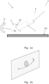
- Fig. 1a illustrates an embodiment of a machining tool 1 during use.
- the machining tool 1 comprises a motor 2, a shaft 3, and a machining element 4.
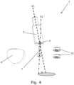
- the motor 2 is arranged to rotate the shaft 3 about a first axis of rotation X1 (see Fig. 4 ) as indicated by the arrow A.
- the motor 2 is schematically illustrated at a distance from the shaft 2 and connected to the shaft by a dotted line.
- the machining element 4 is rotational attached to the shaft 3 for rotation about a second axis of rotation X2 (see Fig. 4 ).
- the first axis of rotation X1 and the second axis of rotation X2 form an angle ⁇ (see Fig. 4 ), so that the first axis of rotation X1 and the second axis of rotation X2 are non-parallel.
- the machining element 4 comprising an outer surface 5 being configured to machine a surface 100 of a workpiece. In the specific embodiment, the outer surface is configured for polishing.
- the outer surface 5 of the machining element 4 comprises a curved surface, as the outer surfaces 5 is shaped substantially as a fraction of a sphere, i.e., the outer surface 5 forms of a sphere part 5A and a plane surface part 5B.
- An indentation 6 is formed in the outer surface 5 in the plane surface part 5B hereof.
- rotation of the machining element may be converted into oscillation as indicated by the arrow B.
- the arrow B extends in a plane, which indicates a pure nodding movement which is obtained when ⁇ 3 is zero.
- Fig. 1b illustrates the arrow B in a cross-section plane.
- the oscillation is herein generally referred to as a nodding movement.
- the illustrated pure nodding movement requires ⁇ 3 to be zero.
- Fig. 2 illustrates another view of the embodiment of the machining tool illustrated in Fig. 1 .
- the motor is not shown in Fig. 2 .
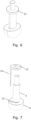
- Figs. 3-5 illustrate different exploded views of the embodiment of the machining tool 1 illustrated in Figs. 1 and 2 .
- the machining element 4 is in the illustrated embodiment attached to the shaft 3 via an interface 7, which interface 7 is elongated and extends along the second axis of rotation X2 (see Fig. 4 ). Thereby, the interface 7 forms an extension to the shaft 3 extending non-parallel to the shaft.
- the machining element forms a section of a sphere and the centre of the sphere is located where the first and second axis of rotation intersects. This provides the advantage that the machining element oscillates identically in all directions. Combined with the spherical shape that provides a machining pattern which is identical irrespective where the machining element is in contact with the surface to be treated.
- Fig. 3 illustrates an opening 8 formed in an end portion 9 of the shaft 3.
- the interface 7 is inserted in the opening 8 and extends off-set from the centre of the end portion 9 of the shaft 3.
- the interface 7 is fixedly arranged relative to the shaft 3, whereby the interface 7 does not rotate relative to the shaft 3.
- the interface 7 and the shaft 3 are formed as two separate elements which are subsequently attached to each other.
- the machining element 4 is rotationally attached to the shaft 3 by being rotationally attached to the interface 7. This is achieved by use of a bearing structure, in this embodiment including two ball bearings 10.
- the ball bearings 10 are circumferential arranged relative to a first end 11 of the interface 7, and they are arranged in the indentation 6 (see Fig. 5 ) in the machining element 4.
- a flow path 12 (illustrated by the dotted line in Fig. 5 ) extends through the shaft 3 to the machining element 4.
- the flow path 12 is arranged for a flow of an abrasive.
- the abrasive and a liquid may alternatingly flow in the flow path 12.
- the outer surface 5 of the machining element 4 comprises an opening 13 arranged in communication with the flow path 12 to allow discharge of the abrasive and/or liquid.
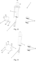
- Figs. 6 and 7 illustrate an alternative embodiment comprising a restriction structure configured for controlling the balance of translation.
- the restriction structure comprises a restriction element 13 and a connector 14, the latter being received in an indentation 15 in the machining element 4.
- the restriction structure may rotate with a rotational speed ⁇ 3, particularly a speed which is different from the rotational speed ⁇ 1 by which the shaft 3 rotates about the first axis of rotation.
- the rotational speed ⁇ 3 may be anything from zero to the speed ⁇ 1.
- the restriction element 13 is fixed to a non-rotating point and in another embodiment, the restriction element 13 is rotated by a motor at a speed different from the rotation speed of the shaft 3.
- the restriction structure limits rotation of the machining element 4 about the first axis of rotation X1 and thereby forces rotation of the machining element 4 to rotate about the second axis of rotation X2 relative to the shaft 3 when the shaft rotates.
- the rotational speed ⁇ 3 is zero, or when the machining element 4 is prevented from rotating by friction against the workpiece, the movement of the machining element becomes pure oscillation without rotation.
- Figs. 8-9 illustrate different embodiments of the machining element 4.
- the machining element 4 comprises a base 81 and one or more projections 82.
- the outer surface 83 of the projection 82 may form a fraction of a sphere. Due to the elongated shape of the projection, it may enter narrow spaces wherein the outer surface 83 may be used for polishing, grinding, or deburring purposes.
- the machining element 4 comprises a base 81 and a plurality of projections 91.
- the projections 91 are soft, resilient elements e.g., made of rubber. These projections will engage the work piece and prevent rotation of the machining element 4 while the outer surface 5 of the machining element 4 provides surface treatment of the work piece.
Landscapes
- Engineering & Computer Science (AREA)
- Mechanical Engineering (AREA)
- Finish Polishing, Edge Sharpening, And Grinding By Specific Grinding Devices (AREA)
Claims (15)
- Outil d'usinage (1) comprenant un moteur et un appareil, l'appareil comprenant :- un arbre (3) qui peut être entraîné en rotation par le moteur (2) autour d'un premier axe (X1) de rotation, et- un élément d'usinage (4) présentant une surface extérieure (5) formant une surface de contact pour le traitement d'une pièce à usiner et étant fixé à l'arbre (3) pour une rotation par rapport à l'arbre (3) autour d'un deuxième axe (X2) de rotation,dans lequel le premier axe (X1) de rotation et le deuxième axe (X2) de rotation forment un angle oblique (α), de sorte que le premier axe (X1) de rotation et le deuxième axe (X2) de rotation sont non parallèles et non perpendiculaires.
- Outil d'usinage selon la revendication 1, dans lequel la surface de contact est incurvée.
- Outil d'usinage selon la revendication 2, dans lequel la surface de contact incurvée forme une fraction d'une sphère (5A).
- Outil d'usinage selon la revendication 3, dans lequel la sphère forme un point central (P) où le premier axe de rotation coupe le deuxième axe de rotation.
- Outil d'usinage selon l'une quelconque des revendications précédentes, comprenant une structure de restriction (13, 14, 15) configurée pour restreindre la rotation de l'élément d'usinage (4) autour du premier axe (X1) de rotation.
- Outil d'usinage ou appareil selon la revendication 5, dans lequel la structure de restriction (13, 14, 15) est configurée, en limitant la rotation de l'élément d'usinage (4) autour du premier axe (X1) de rotation, pour forcer l'élément d'usinage (4) à tourner autour du deuxième axe (X2) de rotation.
- Outil d'usinage selon l'une quelconque des revendications précédentes, dans lequel l'angle α est compris entre 4 et 80 degrés.
- Outil d'usinage selon l'une quelconque des revendications précédentes, dans lequel l'élément d'usinage (4) est relié de manière rigide à l'arbre pour définir l'angle α comme un angle fixe qui n'est pas réglable.
- Outil d'usinage selon l'une quelconque des revendications précédentes, dans lequel l'élément d'usinage (4) est fixé à l'arbre via une interface (7), l'interface (7) étant allongée et s'étendant le long du deuxième axe de rotation.
- Outil d'usinage selon la revendication 9, dans lequel l'interface (7) s'étend dans une ouverture (8) dans une partie d'extrémité (9) de l'arbre (3) dans une cavité allongée dans l'arbre.
- Outil d'usinage selon la revendication 9 ou 10, dans lequel l'interface (7) s'étend dans une indentation dans l'élément d'usinage (4).
- Outil d'usinage selon l'une quelconque des revendications précédentes, dans lequel l'élément d'usinage (4) est fixé en rotation à l'arbre via au moins une structure de palier (10).
- Outil d'usinage selon l'une quelconque des revendications 9 à 12, dans lequel l'interface (7) est disposée de manière rotative par rapport à l'arbre (3).
- Outil d'usinage selon l'une quelconque des revendications 9 à 12, dans lequel l'interface (7) est disposée de manière fixe par rapport à l'arbre (3).
- Procédé d'usinage d'une surface au moyen d'un outil d'usinage (1) selon l'une quelconque des revendications précédentes ; le procédé comprenant les étapes consistant à :- fournir l'outil d'usinage (1) selon l'une quelconque des revendications précédentes ;- activer le moteur (2) pour faire tourner l'arbre (3) ;- amener l'élément d'usinage (4) en contact avec la surface ;- créer une rotation relative de l'élément d'usinage (4) par rapport à l'arbre (3) autour du deuxième axe de rotation (X2), la rotation relative établissant un mouvement oscillant de l'élément d'usinage (4) par rapport à l'arbre (3) ; et- déplacer l'élément d'usinage (4) le long de la surface.
Applications Claiming Priority (2)
| Application Number | Priority Date | Filing Date | Title |
|---|---|---|---|
| EP20194817 | 2020-09-07 | ||
| PCT/EP2021/074570 WO2022049303A1 (fr) | 2020-09-07 | 2021-09-07 | Outil d'usinage |
Publications (3)
| Publication Number | Publication Date |
|---|---|
| EP4210904A1 EP4210904A1 (fr) | 2023-07-19 |
| EP4210904C0 EP4210904C0 (fr) | 2025-05-14 |
| EP4210904B1 true EP4210904B1 (fr) | 2025-05-14 |
Family
ID=72422131
Family Applications (1)
| Application Number | Title | Priority Date | Filing Date |
|---|---|---|---|
| EP21773364.1A Active EP4210904B1 (fr) | 2020-09-07 | 2021-09-07 | Outil d'usinage et procédé |
Country Status (2)
| Country | Link |
|---|---|
| EP (1) | EP4210904B1 (fr) |
| WO (1) | WO2022049303A1 (fr) |
Family Cites Families (4)
| Publication number | Priority date | Publication date | Assignee | Title |
|---|---|---|---|---|
| JPH1086050A (ja) | 1996-09-19 | 1998-04-07 | Asahi Optical Co Ltd | 研磨工具 |
| JP2002154040A (ja) * | 2000-11-20 | 2002-05-28 | Ikegami Kanagata Kogyo Kk | 回転工具 |
| DE10321670A1 (de) * | 2002-05-17 | 2004-12-30 | Gühring, Jörg, Dr. | Werkzeug, Vorrichtung und Verfahren zum Entgraten von Bohrungen |
| US20190337062A1 (en) * | 2013-07-31 | 2019-11-07 | Daido Die & Mold Steel Solutions Co., Ltd. | Method of manufacturing an elbow, cutting tool, and elbow |
-
2021
- 2021-09-07 EP EP21773364.1A patent/EP4210904B1/fr active Active
- 2021-09-07 WO PCT/EP2021/074570 patent/WO2022049303A1/fr not_active Ceased
Also Published As
| Publication number | Publication date |
|---|---|
| WO2022049303A1 (fr) | 2022-03-10 |
| EP4210904C0 (fr) | 2025-05-14 |
| EP4210904A1 (fr) | 2023-07-19 |
Similar Documents
| Publication | Publication Date | Title |
|---|---|---|
| KR101750035B1 (ko) | 면취기 | |
| CN110948380A (zh) | 一种行星研磨装置以及行星研磨装置的去除函数优化方法 | |
| US6475066B2 (en) | Random-orbit head with concentric lock-up feature | |
| EP4210904B1 (fr) | Outil d'usinage et procédé | |
| KR101639782B1 (ko) | 연마휠용 드레싱 장치 | |
| JP2002263995A (ja) | 球面の研削加工方法及び装置 | |
| KR20120065712A (ko) | 볼 연마장치 | |
| JP6085871B2 (ja) | 刃先交換型切削インサート、切削インサートホルダ、切削工具、旋削装置および旋削方法 | |
| CN214351737U (zh) | 一种研磨垫修整器及化学机械研磨设备 | |
| JP6529611B2 (ja) | 被加工物の加工方法、研磨機用ブラシ及び工具ホルダ | |
| KR101949158B1 (ko) | 전동공구의 회전력 전달장치 | |
| JP3990205B2 (ja) | 研磨装置 | |
| JP5425570B2 (ja) | トリポード型等速ジョイントのトラニオンの加工方法及び装置 | |
| CN208614546U (zh) | 一种非线性rrl型三轴数控抛磨加工机床的磨盘机构 | |
| JPH0431820B2 (fr) | ||
| CA2842480A1 (fr) | Carottier abrasif | |
| JP2011051046A (ja) | 加工方法及び加工装置 | |
| JP7775391B1 (ja) | 研磨工具 | |
| KR200378324Y1 (ko) | 연마기용 조정롤러 | |
| CN215147645U (zh) | 一种用于多晶体的圆形打磨机 | |
| KR100489703B1 (ko) | 공작기계 헤드 인터페이스와 그 연마 및 연삭공구 | |
| JPH01153258A (ja) | 研磨装置 | |
| JP6897999B2 (ja) | 軸体支持具および工具 | |
| JP2004255549A (ja) | 球面の研削・研磨工具および球面の研削・研磨加工方法 | |
| JPH04331058A (ja) | 凹レンズ加工方法および装置 |
Legal Events
| Date | Code | Title | Description |
|---|---|---|---|
| STAA | Information on the status of an ep patent application or granted ep patent |
Free format text: STATUS: UNKNOWN |
|
| STAA | Information on the status of an ep patent application or granted ep patent |
Free format text: STATUS: THE INTERNATIONAL PUBLICATION HAS BEEN MADE |
|
| PUAI | Public reference made under article 153(3) epc to a published international application that has entered the european phase |
Free format text: ORIGINAL CODE: 0009012 |
|
| STAA | Information on the status of an ep patent application or granted ep patent |
Free format text: STATUS: REQUEST FOR EXAMINATION WAS MADE |
|
| 17P | Request for examination filed |
Effective date: 20230411 |
|
| AK | Designated contracting states |
Kind code of ref document: A1 Designated state(s): AL AT BE BG CH CY CZ DE DK EE ES FI FR GB GR HR HU IE IS IT LI LT LU LV MC MK MT NL NO PL PT RO RS SE SI SK SM TR |
|
| DAV | Request for validation of the european patent (deleted) | ||
| DAX | Request for extension of the european patent (deleted) | ||
| GRAP | Despatch of communication of intention to grant a patent |
Free format text: ORIGINAL CODE: EPIDOSNIGR1 |
|
| STAA | Information on the status of an ep patent application or granted ep patent |
Free format text: STATUS: GRANT OF PATENT IS INTENDED |
|
| INTG | Intention to grant announced |
Effective date: 20241008 |
|
| GRAJ | Information related to disapproval of communication of intention to grant by the applicant or resumption of examination proceedings by the epo deleted |
Free format text: ORIGINAL CODE: EPIDOSDIGR1 |
|
| STAA | Information on the status of an ep patent application or granted ep patent |
Free format text: STATUS: REQUEST FOR EXAMINATION WAS MADE |
|
| INTC | Intention to grant announced (deleted) | ||
| GRAP | Despatch of communication of intention to grant a patent |
Free format text: ORIGINAL CODE: EPIDOSNIGR1 |
|
| STAA | Information on the status of an ep patent application or granted ep patent |
Free format text: STATUS: GRANT OF PATENT IS INTENDED |
|
| INTG | Intention to grant announced |
Effective date: 20250218 |
|
| GRAS | Grant fee paid |
Free format text: ORIGINAL CODE: EPIDOSNIGR3 |
|
| GRAA | (expected) grant |
Free format text: ORIGINAL CODE: 0009210 |
|
| STAA | Information on the status of an ep patent application or granted ep patent |
Free format text: STATUS: THE PATENT HAS BEEN GRANTED |
|
| AK | Designated contracting states |
Kind code of ref document: B1 Designated state(s): AL AT BE BG CH CY CZ DE DK EE ES FI FR GB GR HR HU IE IS IT LI LT LU LV MC MK MT NL NO PL PT RO RS SE SI SK SM TR |
|
| REG | Reference to a national code |
Ref country code: GB Ref legal event code: FG4D |
|
| REG | Reference to a national code |
Ref country code: CH Ref legal event code: EP |
|
| REG | Reference to a national code |
Ref country code: IE Ref legal event code: FG4D |
|
| REG | Reference to a national code |
Ref country code: DE Ref legal event code: R096 Ref document number: 602021030841 Country of ref document: DE |
|
| U01 | Request for unitary effect filed |
Effective date: 20250526 |
|
| U07 | Unitary effect registered |
Designated state(s): AT BE BG DE DK EE FI FR IT LT LU LV MT NL PT RO SE SI Effective date: 20250603 |
|
| PG25 | Lapsed in a contracting state [announced via postgrant information from national office to epo] |
Ref country code: ES Free format text: LAPSE BECAUSE OF FAILURE TO SUBMIT A TRANSLATION OF THE DESCRIPTION OR TO PAY THE FEE WITHIN THE PRESCRIBED TIME-LIMIT Effective date: 20250514 |
|
| PG25 | Lapsed in a contracting state [announced via postgrant information from national office to epo] |
Ref country code: NO Free format text: LAPSE BECAUSE OF FAILURE TO SUBMIT A TRANSLATION OF THE DESCRIPTION OR TO PAY THE FEE WITHIN THE PRESCRIBED TIME-LIMIT Effective date: 20250814 Ref country code: GR Free format text: LAPSE BECAUSE OF FAILURE TO SUBMIT A TRANSLATION OF THE DESCRIPTION OR TO PAY THE FEE WITHIN THE PRESCRIBED TIME-LIMIT Effective date: 20250815 |
|
| PG25 | Lapsed in a contracting state [announced via postgrant information from national office to epo] |
Ref country code: PL Free format text: LAPSE BECAUSE OF FAILURE TO SUBMIT A TRANSLATION OF THE DESCRIPTION OR TO PAY THE FEE WITHIN THE PRESCRIBED TIME-LIMIT Effective date: 20250514 |
|
| PG25 | Lapsed in a contracting state [announced via postgrant information from national office to epo] |
Ref country code: HR Free format text: LAPSE BECAUSE OF FAILURE TO SUBMIT A TRANSLATION OF THE DESCRIPTION OR TO PAY THE FEE WITHIN THE PRESCRIBED TIME-LIMIT Effective date: 20250514 |
|
| PG25 | Lapsed in a contracting state [announced via postgrant information from national office to epo] |
Ref country code: RS Free format text: LAPSE BECAUSE OF FAILURE TO SUBMIT A TRANSLATION OF THE DESCRIPTION OR TO PAY THE FEE WITHIN THE PRESCRIBED TIME-LIMIT Effective date: 20250814 |
|
| PG25 | Lapsed in a contracting state [announced via postgrant information from national office to epo] |
Ref country code: IS Free format text: LAPSE BECAUSE OF FAILURE TO SUBMIT A TRANSLATION OF THE DESCRIPTION OR TO PAY THE FEE WITHIN THE PRESCRIBED TIME-LIMIT Effective date: 20250914 |
|
| U20 | Renewal fee for the european patent with unitary effect paid |
Year of fee payment: 5 Effective date: 20250930 |
|
| PG25 | Lapsed in a contracting state [announced via postgrant information from national office to epo] |
Ref country code: SM Free format text: LAPSE BECAUSE OF FAILURE TO SUBMIT A TRANSLATION OF THE DESCRIPTION OR TO PAY THE FEE WITHIN THE PRESCRIBED TIME-LIMIT Effective date: 20250514 |
|
| PG25 | Lapsed in a contracting state [announced via postgrant information from national office to epo] |
Ref country code: CZ Free format text: LAPSE BECAUSE OF FAILURE TO SUBMIT A TRANSLATION OF THE DESCRIPTION OR TO PAY THE FEE WITHIN THE PRESCRIBED TIME-LIMIT Effective date: 20250514 |
|
| PG25 | Lapsed in a contracting state [announced via postgrant information from national office to epo] |
Ref country code: SK Free format text: LAPSE BECAUSE OF FAILURE TO SUBMIT A TRANSLATION OF THE DESCRIPTION OR TO PAY THE FEE WITHIN THE PRESCRIBED TIME-LIMIT Effective date: 20250514 |
|
| PLBE | No opposition filed within time limit |
Free format text: ORIGINAL CODE: 0009261 |
|
| STAA | Information on the status of an ep patent application or granted ep patent |
Free format text: STATUS: NO OPPOSITION FILED WITHIN TIME LIMIT |
|
| REG | Reference to a national code |
Ref country code: CH Ref legal event code: L10 Free format text: ST27 STATUS EVENT CODE: U-0-0-L10-L00 (AS PROVIDED BY THE NATIONAL OFFICE) Effective date: 20260325 |
|
| 26N | No opposition filed |
Effective date: 20260217 |