EP4210932B1 - Procédé et dispositif destiné au soudage d'au moins deux sections profilées servant aux cadres de fenêtre ou de porte ou aux battants - Google Patents
Procédé et dispositif destiné au soudage d'au moins deux sections profilées servant aux cadres de fenêtre ou de porte ou aux battants Download PDFInfo
- Publication number
- EP4210932B1 EP4210932B1 EP21762655.5A EP21762655A EP4210932B1 EP 4210932 B1 EP4210932 B1 EP 4210932B1 EP 21762655 A EP21762655 A EP 21762655A EP 4210932 B1 EP4210932 B1 EP 4210932B1
- Authority
- EP
- European Patent Office
- Prior art keywords
- profile
- joining
- heating
- profiles
- melting
- Prior art date
- Legal status (The legal status is an assumption and is not a legal conclusion. Google has not performed a legal analysis and makes no representation as to the accuracy of the status listed.)
- Active
Links
Images





Classifications
-
- B—PERFORMING OPERATIONS; TRANSPORTING
- B29—WORKING OF PLASTICS; WORKING OF SUBSTANCES IN A PLASTIC STATE IN GENERAL
- B29C—SHAPING OR JOINING OF PLASTICS; SHAPING OF MATERIAL IN A PLASTIC STATE, NOT OTHERWISE PROVIDED FOR; AFTER-TREATMENT OF THE SHAPED PRODUCTS, e.g. REPAIRING
- B29C65/00—Joining or sealing of preformed parts, e.g. welding of plastics materials; Apparatus therefor
- B29C65/02—Joining or sealing of preformed parts, e.g. welding of plastics materials; Apparatus therefor by heating, with or without pressure
- B29C65/18—Joining or sealing of preformed parts, e.g. welding of plastics materials; Apparatus therefor by heating, with or without pressure using heated tools
- B29C65/20—Joining or sealing of preformed parts, e.g. welding of plastics materials; Apparatus therefor by heating, with or without pressure using heated tools with direct contact, e.g. using "mirror"
-
- B—PERFORMING OPERATIONS; TRANSPORTING
- B29—WORKING OF PLASTICS; WORKING OF SUBSTANCES IN A PLASTIC STATE IN GENERAL
- B29C—SHAPING OR JOINING OF PLASTICS; SHAPING OF MATERIAL IN A PLASTIC STATE, NOT OTHERWISE PROVIDED FOR; AFTER-TREATMENT OF THE SHAPED PRODUCTS, e.g. REPAIRING
- B29C65/00—Joining or sealing of preformed parts, e.g. welding of plastics materials; Apparatus therefor
- B29C65/02—Joining or sealing of preformed parts, e.g. welding of plastics materials; Apparatus therefor by heating, with or without pressure
- B29C65/18—Joining or sealing of preformed parts, e.g. welding of plastics materials; Apparatus therefor by heating, with or without pressure using heated tools
- B29C65/20—Joining or sealing of preformed parts, e.g. welding of plastics materials; Apparatus therefor by heating, with or without pressure using heated tools with direct contact, e.g. using "mirror"
- B29C65/2007—Joining or sealing of preformed parts, e.g. welding of plastics materials; Apparatus therefor by heating, with or without pressure using heated tools with direct contact, e.g. using "mirror" characterised by the type of welding mirror
- B29C65/2023—Joining or sealing of preformed parts, e.g. welding of plastics materials; Apparatus therefor by heating, with or without pressure using heated tools with direct contact, e.g. using "mirror" characterised by the type of welding mirror said welding mirror comprising several sectors
-
- B—PERFORMING OPERATIONS; TRANSPORTING
- B29—WORKING OF PLASTICS; WORKING OF SUBSTANCES IN A PLASTIC STATE IN GENERAL
- B29C—SHAPING OR JOINING OF PLASTICS; SHAPING OF MATERIAL IN A PLASTIC STATE, NOT OTHERWISE PROVIDED FOR; AFTER-TREATMENT OF THE SHAPED PRODUCTS, e.g. REPAIRING
- B29C65/00—Joining or sealing of preformed parts, e.g. welding of plastics materials; Apparatus therefor
- B29C65/02—Joining or sealing of preformed parts, e.g. welding of plastics materials; Apparatus therefor by heating, with or without pressure
- B29C65/18—Joining or sealing of preformed parts, e.g. welding of plastics materials; Apparatus therefor by heating, with or without pressure using heated tools
- B29C65/20—Joining or sealing of preformed parts, e.g. welding of plastics materials; Apparatus therefor by heating, with or without pressure using heated tools with direct contact, e.g. using "mirror"
- B29C65/2007—Joining or sealing of preformed parts, e.g. welding of plastics materials; Apparatus therefor by heating, with or without pressure using heated tools with direct contact, e.g. using "mirror" characterised by the type of welding mirror
- B29C65/203—Joining or sealing of preformed parts, e.g. welding of plastics materials; Apparatus therefor by heating, with or without pressure using heated tools with direct contact, e.g. using "mirror" characterised by the type of welding mirror being several single mirrors, e.g. not mounted on the same tool
-
- B—PERFORMING OPERATIONS; TRANSPORTING
- B29—WORKING OF PLASTICS; WORKING OF SUBSTANCES IN A PLASTIC STATE IN GENERAL
- B29C—SHAPING OR JOINING OF PLASTICS; SHAPING OF MATERIAL IN A PLASTIC STATE, NOT OTHERWISE PROVIDED FOR; AFTER-TREATMENT OF THE SHAPED PRODUCTS, e.g. REPAIRING
- B29C65/00—Joining or sealing of preformed parts, e.g. welding of plastics materials; Apparatus therefor
- B29C65/02—Joining or sealing of preformed parts, e.g. welding of plastics materials; Apparatus therefor by heating, with or without pressure
- B29C65/18—Joining or sealing of preformed parts, e.g. welding of plastics materials; Apparatus therefor by heating, with or without pressure using heated tools
- B29C65/20—Joining or sealing of preformed parts, e.g. welding of plastics materials; Apparatus therefor by heating, with or without pressure using heated tools with direct contact, e.g. using "mirror"
- B29C65/2046—Joining or sealing of preformed parts, e.g. welding of plastics materials; Apparatus therefor by heating, with or without pressure using heated tools with direct contact, e.g. using "mirror" using a welding mirror which also cuts the parts to be joined, e.g. for sterile welding
-
- B—PERFORMING OPERATIONS; TRANSPORTING
- B29—WORKING OF PLASTICS; WORKING OF SUBSTANCES IN A PLASTIC STATE IN GENERAL
- B29C—SHAPING OR JOINING OF PLASTICS; SHAPING OF MATERIAL IN A PLASTIC STATE, NOT OTHERWISE PROVIDED FOR; AFTER-TREATMENT OF THE SHAPED PRODUCTS, e.g. REPAIRING
- B29C65/00—Joining or sealing of preformed parts, e.g. welding of plastics materials; Apparatus therefor
- B29C65/02—Joining or sealing of preformed parts, e.g. welding of plastics materials; Apparatus therefor by heating, with or without pressure
- B29C65/18—Joining or sealing of preformed parts, e.g. welding of plastics materials; Apparatus therefor by heating, with or without pressure using heated tools
- B29C65/20—Joining or sealing of preformed parts, e.g. welding of plastics materials; Apparatus therefor by heating, with or without pressure using heated tools with direct contact, e.g. using "mirror"
- B29C65/2053—Joining or sealing of preformed parts, e.g. welding of plastics materials; Apparatus therefor by heating, with or without pressure using heated tools with direct contact, e.g. using "mirror" characterised by special ways of bringing the welding mirrors into position
- B29C65/2061—Joining or sealing of preformed parts, e.g. welding of plastics materials; Apparatus therefor by heating, with or without pressure using heated tools with direct contact, e.g. using "mirror" characterised by special ways of bringing the welding mirrors into position by sliding
-
- B—PERFORMING OPERATIONS; TRANSPORTING
- B29—WORKING OF PLASTICS; WORKING OF SUBSTANCES IN A PLASTIC STATE IN GENERAL
- B29C—SHAPING OR JOINING OF PLASTICS; SHAPING OF MATERIAL IN A PLASTIC STATE, NOT OTHERWISE PROVIDED FOR; AFTER-TREATMENT OF THE SHAPED PRODUCTS, e.g. REPAIRING
- B29C65/00—Joining or sealing of preformed parts, e.g. welding of plastics materials; Apparatus therefor
- B29C65/02—Joining or sealing of preformed parts, e.g. welding of plastics materials; Apparatus therefor by heating, with or without pressure
- B29C65/18—Joining or sealing of preformed parts, e.g. welding of plastics materials; Apparatus therefor by heating, with or without pressure using heated tools
- B29C65/20—Joining or sealing of preformed parts, e.g. welding of plastics materials; Apparatus therefor by heating, with or without pressure using heated tools with direct contact, e.g. using "mirror"
- B29C65/2053—Joining or sealing of preformed parts, e.g. welding of plastics materials; Apparatus therefor by heating, with or without pressure using heated tools with direct contact, e.g. using "mirror" characterised by special ways of bringing the welding mirrors into position
- B29C65/2061—Joining or sealing of preformed parts, e.g. welding of plastics materials; Apparatus therefor by heating, with or without pressure using heated tools with direct contact, e.g. using "mirror" characterised by special ways of bringing the welding mirrors into position by sliding
- B29C65/2069—Joining or sealing of preformed parts, e.g. welding of plastics materials; Apparatus therefor by heating, with or without pressure using heated tools with direct contact, e.g. using "mirror" characterised by special ways of bringing the welding mirrors into position by sliding with an angle with respect to the plane comprising the parts to be joined
- B29C65/2076—Joining or sealing of preformed parts, e.g. welding of plastics materials; Apparatus therefor by heating, with or without pressure using heated tools with direct contact, e.g. using "mirror" characterised by special ways of bringing the welding mirrors into position by sliding with an angle with respect to the plane comprising the parts to be joined perpendicularly to the plane comprising the parts to be joined
-
- B—PERFORMING OPERATIONS; TRANSPORTING
- B29—WORKING OF PLASTICS; WORKING OF SUBSTANCES IN A PLASTIC STATE IN GENERAL
- B29C—SHAPING OR JOINING OF PLASTICS; SHAPING OF MATERIAL IN A PLASTIC STATE, NOT OTHERWISE PROVIDED FOR; AFTER-TREATMENT OF THE SHAPED PRODUCTS, e.g. REPAIRING
- B29C65/00—Joining or sealing of preformed parts, e.g. welding of plastics materials; Apparatus therefor
- B29C65/02—Joining or sealing of preformed parts, e.g. welding of plastics materials; Apparatus therefor by heating, with or without pressure
- B29C65/18—Joining or sealing of preformed parts, e.g. welding of plastics materials; Apparatus therefor by heating, with or without pressure using heated tools
- B29C65/20—Joining or sealing of preformed parts, e.g. welding of plastics materials; Apparatus therefor by heating, with or without pressure using heated tools with direct contact, e.g. using "mirror"
- B29C65/2092—Joining or sealing of preformed parts, e.g. welding of plastics materials; Apparatus therefor by heating, with or without pressure using heated tools with direct contact, e.g. using "mirror" and involving the use of a facer
-
- B—PERFORMING OPERATIONS; TRANSPORTING
- B29—WORKING OF PLASTICS; WORKING OF SUBSTANCES IN A PLASTIC STATE IN GENERAL
- B29C—SHAPING OR JOINING OF PLASTICS; SHAPING OF MATERIAL IN A PLASTIC STATE, NOT OTHERWISE PROVIDED FOR; AFTER-TREATMENT OF THE SHAPED PRODUCTS, e.g. REPAIRING
- B29C65/00—Joining or sealing of preformed parts, e.g. welding of plastics materials; Apparatus therefor
- B29C65/74—Joining or sealing of preformed parts, e.g. welding of plastics materials; Apparatus therefor by welding and severing, or by joining and severing, the severing being performed in the area to be joined, next to the area to be joined, in the joint area or next to the joint area
- B29C65/743—Joining or sealing of preformed parts, e.g. welding of plastics materials; Apparatus therefor by welding and severing, or by joining and severing, the severing being performed in the area to be joined, next to the area to be joined, in the joint area or next to the joint area using the same tool for both joining and severing, said tool being monobloc or formed by several parts mounted together and forming a monobloc
-
- B—PERFORMING OPERATIONS; TRANSPORTING
- B29—WORKING OF PLASTICS; WORKING OF SUBSTANCES IN A PLASTIC STATE IN GENERAL
- B29C—SHAPING OR JOINING OF PLASTICS; SHAPING OF MATERIAL IN A PLASTIC STATE, NOT OTHERWISE PROVIDED FOR; AFTER-TREATMENT OF THE SHAPED PRODUCTS, e.g. REPAIRING
- B29C66/00—General aspects of processes or apparatus for joining preformed parts
- B29C66/004—Preventing sticking together, e.g. of some areas of the parts to be joined
- B29C66/0042—Preventing sticking together, e.g. of some areas of the parts to be joined of the joining tool and the parts to be joined
-
- B—PERFORMING OPERATIONS; TRANSPORTING
- B29—WORKING OF PLASTICS; WORKING OF SUBSTANCES IN A PLASTIC STATE IN GENERAL
- B29C—SHAPING OR JOINING OF PLASTICS; SHAPING OF MATERIAL IN A PLASTIC STATE, NOT OTHERWISE PROVIDED FOR; AFTER-TREATMENT OF THE SHAPED PRODUCTS, e.g. REPAIRING
- B29C66/00—General aspects of processes or apparatus for joining preformed parts
- B29C66/01—General aspects dealing with the joint area or with the area to be joined
- B29C66/02—Preparation of the material, in the area to be joined, prior to joining or welding
- B29C66/022—Mechanical pre-treatments, e.g. reshaping
- B29C66/0224—Mechanical pre-treatments, e.g. reshaping with removal of material
- B29C66/02241—Cutting, e.g. by using waterjets, or sawing
-
- B—PERFORMING OPERATIONS; TRANSPORTING
- B29—WORKING OF PLASTICS; WORKING OF SUBSTANCES IN A PLASTIC STATE IN GENERAL
- B29C—SHAPING OR JOINING OF PLASTICS; SHAPING OF MATERIAL IN A PLASTIC STATE, NOT OTHERWISE PROVIDED FOR; AFTER-TREATMENT OF THE SHAPED PRODUCTS, e.g. REPAIRING
- B29C66/00—General aspects of processes or apparatus for joining preformed parts
- B29C66/01—General aspects dealing with the joint area or with the area to be joined
- B29C66/05—Particular design of joint configurations
- B29C66/10—Particular design of joint configurations particular design of the joint cross-sections
- B29C66/11—Joint cross-sections comprising a single joint-segment, i.e. one of the parts to be joined comprising a single joint-segment in the joint cross-section
- B29C66/116—Single bevelled joints, i.e. one of the parts to be joined being bevelled in the joint area
- B29C66/1162—Single bevel to bevel joints, e.g. mitre joints
-
- B—PERFORMING OPERATIONS; TRANSPORTING
- B29—WORKING OF PLASTICS; WORKING OF SUBSTANCES IN A PLASTIC STATE IN GENERAL
- B29C—SHAPING OR JOINING OF PLASTICS; SHAPING OF MATERIAL IN A PLASTIC STATE, NOT OTHERWISE PROVIDED FOR; AFTER-TREATMENT OF THE SHAPED PRODUCTS, e.g. REPAIRING
- B29C66/00—General aspects of processes or apparatus for joining preformed parts
- B29C66/01—General aspects dealing with the joint area or with the area to be joined
- B29C66/32—Measures for keeping the burr form under control; Avoiding burr formation; Shaping the burr
- B29C66/324—Avoiding burr formation
-
- B—PERFORMING OPERATIONS; TRANSPORTING
- B29—WORKING OF PLASTICS; WORKING OF SUBSTANCES IN A PLASTIC STATE IN GENERAL
- B29C—SHAPING OR JOINING OF PLASTICS; SHAPING OF MATERIAL IN A PLASTIC STATE, NOT OTHERWISE PROVIDED FOR; AFTER-TREATMENT OF THE SHAPED PRODUCTS, e.g. REPAIRING
- B29C66/00—General aspects of processes or apparatus for joining preformed parts
- B29C66/01—General aspects dealing with the joint area or with the area to be joined
- B29C66/32—Measures for keeping the burr form under control; Avoiding burr formation; Shaping the burr
- B29C66/326—Shaping the burr, e.g. by the joining tool
-
- B—PERFORMING OPERATIONS; TRANSPORTING
- B29—WORKING OF PLASTICS; WORKING OF SUBSTANCES IN A PLASTIC STATE IN GENERAL
- B29C—SHAPING OR JOINING OF PLASTICS; SHAPING OF MATERIAL IN A PLASTIC STATE, NOT OTHERWISE PROVIDED FOR; AFTER-TREATMENT OF THE SHAPED PRODUCTS, e.g. REPAIRING
- B29C66/00—General aspects of processes or apparatus for joining preformed parts
- B29C66/50—General aspects of joining tubular articles; General aspects of joining long products, i.e. bars or profiled elements; General aspects of joining single elements to tubular articles, hollow articles or bars; General aspects of joining several hollow-preforms to form hollow or tubular articles
- B29C66/51—Joining tubular articles, profiled elements or bars; Joining single elements to tubular articles, hollow articles or bars; Joining several hollow-preforms to form hollow or tubular articles
- B29C66/52—Joining tubular articles, bars or profiled elements
- B29C66/524—Joining profiled elements
- B29C66/5243—Joining profiled elements for forming corner connections, e.g. for making window frames or V-shaped pieces
- B29C66/52431—Joining profiled elements for forming corner connections, e.g. for making window frames or V-shaped pieces with a right angle, e.g. for making L-shaped pieces
-
- B—PERFORMING OPERATIONS; TRANSPORTING
- B29—WORKING OF PLASTICS; WORKING OF SUBSTANCES IN A PLASTIC STATE IN GENERAL
- B29C—SHAPING OR JOINING OF PLASTICS; SHAPING OF MATERIAL IN A PLASTIC STATE, NOT OTHERWISE PROVIDED FOR; AFTER-TREATMENT OF THE SHAPED PRODUCTS, e.g. REPAIRING
- B29C66/00—General aspects of processes or apparatus for joining preformed parts
- B29C66/70—General aspects of processes or apparatus for joining preformed parts characterised by the composition, physical properties or the structure of the material of the parts to be joined; Joining with non-plastics material
- B29C66/71—General aspects of processes or apparatus for joining preformed parts characterised by the composition, physical properties or the structure of the material of the parts to be joined; Joining with non-plastics material characterised by the composition of the plastics material of the parts to be joined
-
- B—PERFORMING OPERATIONS; TRANSPORTING
- B29—WORKING OF PLASTICS; WORKING OF SUBSTANCES IN A PLASTIC STATE IN GENERAL
- B29C—SHAPING OR JOINING OF PLASTICS; SHAPING OF MATERIAL IN A PLASTIC STATE, NOT OTHERWISE PROVIDED FOR; AFTER-TREATMENT OF THE SHAPED PRODUCTS, e.g. REPAIRING
- B29C66/00—General aspects of processes or apparatus for joining preformed parts
- B29C66/70—General aspects of processes or apparatus for joining preformed parts characterised by the composition, physical properties or the structure of the material of the parts to be joined; Joining with non-plastics material
- B29C66/72—General aspects of processes or apparatus for joining preformed parts characterised by the composition, physical properties or the structure of the material of the parts to be joined; Joining with non-plastics material characterised by the structure of the material of the parts to be joined
- B29C66/725—General aspects of processes or apparatus for joining preformed parts characterised by the composition, physical properties or the structure of the material of the parts to be joined; Joining with non-plastics material characterised by the structure of the material of the parts to be joined being hollow-walled or honeycombs
- B29C66/7252—General aspects of processes or apparatus for joining preformed parts characterised by the composition, physical properties or the structure of the material of the parts to be joined; Joining with non-plastics material characterised by the structure of the material of the parts to be joined being hollow-walled or honeycombs hollow-walled
-
- B—PERFORMING OPERATIONS; TRANSPORTING
- B29—WORKING OF PLASTICS; WORKING OF SUBSTANCES IN A PLASTIC STATE IN GENERAL
- B29C—SHAPING OR JOINING OF PLASTICS; SHAPING OF MATERIAL IN A PLASTIC STATE, NOT OTHERWISE PROVIDED FOR; AFTER-TREATMENT OF THE SHAPED PRODUCTS, e.g. REPAIRING
- B29C66/00—General aspects of processes or apparatus for joining preformed parts
- B29C66/70—General aspects of processes or apparatus for joining preformed parts characterised by the composition, physical properties or the structure of the material of the parts to be joined; Joining with non-plastics material
- B29C66/72—General aspects of processes or apparatus for joining preformed parts characterised by the composition, physical properties or the structure of the material of the parts to be joined; Joining with non-plastics material characterised by the structure of the material of the parts to be joined
- B29C66/725—General aspects of processes or apparatus for joining preformed parts characterised by the composition, physical properties or the structure of the material of the parts to be joined; Joining with non-plastics material characterised by the structure of the material of the parts to be joined being hollow-walled or honeycombs
- B29C66/7252—General aspects of processes or apparatus for joining preformed parts characterised by the composition, physical properties or the structure of the material of the parts to be joined; Joining with non-plastics material characterised by the structure of the material of the parts to be joined being hollow-walled or honeycombs hollow-walled
- B29C66/72523—General aspects of processes or apparatus for joining preformed parts characterised by the composition, physical properties or the structure of the material of the parts to be joined; Joining with non-plastics material characterised by the structure of the material of the parts to be joined being hollow-walled or honeycombs hollow-walled multi-channelled or multi-tubular
-
- B—PERFORMING OPERATIONS; TRANSPORTING
- B29—WORKING OF PLASTICS; WORKING OF SUBSTANCES IN A PLASTIC STATE IN GENERAL
- B29C—SHAPING OR JOINING OF PLASTICS; SHAPING OF MATERIAL IN A PLASTIC STATE, NOT OTHERWISE PROVIDED FOR; AFTER-TREATMENT OF THE SHAPED PRODUCTS, e.g. REPAIRING
- B29C66/00—General aspects of processes or apparatus for joining preformed parts
- B29C66/70—General aspects of processes or apparatus for joining preformed parts characterised by the composition, physical properties or the structure of the material of the parts to be joined; Joining with non-plastics material
- B29C66/73—General aspects of processes or apparatus for joining preformed parts characterised by the composition, physical properties or the structure of the material of the parts to be joined; Joining with non-plastics material characterised by the intensive physical properties of the material of the parts to be joined, by the optical properties of the material of the parts to be joined, by the extensive physical properties of the parts to be joined, by the state of the material of the parts to be joined or by the material of the parts to be joined being a thermoplastic or a thermoset
- B29C66/739—General aspects of processes or apparatus for joining preformed parts characterised by the composition, physical properties or the structure of the material of the parts to be joined; Joining with non-plastics material characterised by the intensive physical properties of the material of the parts to be joined, by the optical properties of the material of the parts to be joined, by the extensive physical properties of the parts to be joined, by the state of the material of the parts to be joined or by the material of the parts to be joined being a thermoplastic or a thermoset characterised by the material of the parts to be joined being a thermoplastic or a thermoset
- B29C66/7392—General aspects of processes or apparatus for joining preformed parts characterised by the composition, physical properties or the structure of the material of the parts to be joined; Joining with non-plastics material characterised by the intensive physical properties of the material of the parts to be joined, by the optical properties of the material of the parts to be joined, by the extensive physical properties of the parts to be joined, by the state of the material of the parts to be joined or by the material of the parts to be joined being a thermoplastic or a thermoset characterised by the material of the parts to be joined being a thermoplastic or a thermoset characterised by the material of at least one of the parts being a thermoplastic
- B29C66/73921—General aspects of processes or apparatus for joining preformed parts characterised by the composition, physical properties or the structure of the material of the parts to be joined; Joining with non-plastics material characterised by the intensive physical properties of the material of the parts to be joined, by the optical properties of the material of the parts to be joined, by the extensive physical properties of the parts to be joined, by the state of the material of the parts to be joined or by the material of the parts to be joined being a thermoplastic or a thermoset characterised by the material of the parts to be joined being a thermoplastic or a thermoset characterised by the material of at least one of the parts being a thermoplastic characterised by the materials of both parts being thermoplastics
-
- B—PERFORMING OPERATIONS; TRANSPORTING
- B29—WORKING OF PLASTICS; WORKING OF SUBSTANCES IN A PLASTIC STATE IN GENERAL
- B29C—SHAPING OR JOINING OF PLASTICS; SHAPING OF MATERIAL IN A PLASTIC STATE, NOT OTHERWISE PROVIDED FOR; AFTER-TREATMENT OF THE SHAPED PRODUCTS, e.g. REPAIRING
- B29C66/00—General aspects of processes or apparatus for joining preformed parts
- B29C66/80—General aspects of machine operations or constructions and parts thereof
- B29C66/81—General aspects of the pressing elements, i.e. the elements applying pressure on the parts to be joined in the area to be joined, e.g. the welding jaws or clamps
- B29C66/814—General aspects of the pressing elements, i.e. the elements applying pressure on the parts to be joined in the area to be joined, e.g. the welding jaws or clamps characterised by the design of the pressing elements, e.g. of the welding jaws or clamps
- B29C66/8141—General aspects of the pressing elements, i.e. the elements applying pressure on the parts to be joined in the area to be joined, e.g. the welding jaws or clamps characterised by the design of the pressing elements, e.g. of the welding jaws or clamps characterised by the surface geometry of the part of the pressing elements, e.g. welding jaws or clamps, coming into contact with the parts to be joined
- B29C66/81433—General aspects of the pressing elements, i.e. the elements applying pressure on the parts to be joined in the area to be joined, e.g. the welding jaws or clamps characterised by the design of the pressing elements, e.g. of the welding jaws or clamps characterised by the surface geometry of the part of the pressing elements, e.g. welding jaws or clamps, coming into contact with the parts to be joined being toothed, i.e. comprising several teeth or pins, or being patterned
- B29C66/81435—General aspects of the pressing elements, i.e. the elements applying pressure on the parts to be joined in the area to be joined, e.g. the welding jaws or clamps characterised by the design of the pressing elements, e.g. of the welding jaws or clamps characterised by the surface geometry of the part of the pressing elements, e.g. welding jaws or clamps, coming into contact with the parts to be joined being toothed, i.e. comprising several teeth or pins, or being patterned comprising several parallel ridges, e.g. for crimping
-
- B—PERFORMING OPERATIONS; TRANSPORTING
- B29—WORKING OF PLASTICS; WORKING OF SUBSTANCES IN A PLASTIC STATE IN GENERAL
- B29C—SHAPING OR JOINING OF PLASTICS; SHAPING OF MATERIAL IN A PLASTIC STATE, NOT OTHERWISE PROVIDED FOR; AFTER-TREATMENT OF THE SHAPED PRODUCTS, e.g. REPAIRING
- B29C66/00—General aspects of processes or apparatus for joining preformed parts
- B29C66/80—General aspects of machine operations or constructions and parts thereof
- B29C66/83—General aspects of machine operations or constructions and parts thereof characterised by the movement of the joining or pressing tools
- B29C66/836—Moving relative to and tangentially to the parts to be joined, e.g. transversely to the displacement of the parts to be joined, e.g. using a X-Y table
-
- E—FIXED CONSTRUCTIONS
- E06—DOORS, WINDOWS, SHUTTERS, OR ROLLER BLINDS IN GENERAL; LADDERS
- E06B—FIXED OR MOVABLE CLOSURES FOR OPENINGS IN BUILDINGS, VEHICLES, FENCES OR LIKE ENCLOSURES IN GENERAL, e.g. DOORS, WINDOWS, BLINDS, GATES
- E06B3/00—Window sashes, door leaves, or like elements for closing wall or like openings; Layout of fixed or moving closures, e.g. windows in wall or like openings; Features of rigidly-mounted outer frames relating to the mounting of wing frames
- E06B3/96—Corner joints or edge joints for windows, doors, or the like frames or wings
- E06B3/9604—Welded or soldered joints
- E06B3/9608—Mitre joints
-
- B—PERFORMING OPERATIONS; TRANSPORTING
- B29—WORKING OF PLASTICS; WORKING OF SUBSTANCES IN A PLASTIC STATE IN GENERAL
- B29K—INDEXING SCHEME ASSOCIATED WITH SUBCLASSES B29B, B29C OR B29D, RELATING TO MOULDING MATERIALS OR TO MATERIALS FOR MOULDS, REINFORCEMENTS, FILLERS OR PREFORMED PARTS, e.g. INSERTS
- B29K2027/00—Use of polyvinylhalogenides or derivatives thereof as moulding material
- B29K2027/06—PVC, i.e. polyvinylchloride
-
- B—PERFORMING OPERATIONS; TRANSPORTING
- B29—WORKING OF PLASTICS; WORKING OF SUBSTANCES IN A PLASTIC STATE IN GENERAL
- B29L—INDEXING SCHEME ASSOCIATED WITH SUBCLASS B29C, RELATING TO PARTICULAR ARTICLES
- B29L2031/00—Other particular articles
- B29L2031/001—Profiled members, e.g. beams, sections
- B29L2031/003—Profiled members, e.g. beams, sections having a profiled transverse cross-section
-
- B—PERFORMING OPERATIONS; TRANSPORTING
- B29—WORKING OF PLASTICS; WORKING OF SUBSTANCES IN A PLASTIC STATE IN GENERAL
- B29L—INDEXING SCHEME ASSOCIATED WITH SUBCLASS B29C, RELATING TO PARTICULAR ARTICLES
- B29L2031/00—Other particular articles
- B29L2031/001—Profiled members, e.g. beams, sections
- B29L2031/003—Profiled members, e.g. beams, sections having a profiled transverse cross-section
- B29L2031/005—Profiled members, e.g. beams, sections having a profiled transverse cross-section for making window frames
-
- E—FIXED CONSTRUCTIONS
- E06—DOORS, WINDOWS, SHUTTERS, OR ROLLER BLINDS IN GENERAL; LADDERS
- E06B—FIXED OR MOVABLE CLOSURES FOR OPENINGS IN BUILDINGS, VEHICLES, FENCES OR LIKE ENCLOSURES IN GENERAL, e.g. DOORS, WINDOWS, BLINDS, GATES
- E06B3/00—Window sashes, door leaves, or like elements for closing wall or like openings; Layout of fixed or moving closures, e.g. windows in wall or like openings; Features of rigidly-mounted outer frames relating to the mounting of wing frames
- E06B3/04—Wing frames not characterised by the manner of movement
- E06B3/06—Single frames
- E06B3/08—Constructions depending on the use of specified materials
- E06B3/20—Constructions depending on the use of specified materials of plastics
- E06B3/22—Hollow frames
Definitions
- the invention relates to a method for welding at least two profiles for window or door frames or sashes according to the preamble of claim 1 and to a device for welding at least two profiles according to the preamble of claim 11.
- the actual welding of the profile parts within the meaning of the present invention is carried out by melting and subsequent joining of the joining surfaces at the profile bar ends.
- the profile parts to be welded are first placed in a corresponding clamping device and positioned relative to each other using stops and guides in the device.
- the joining surfaces are then pressed against the heating surface of a heating element of the welding device in a melting step.
- material of the respective The profile part is melted at its joining surface, creating the melt required for the weld—material that has become liquid or pasty due to the heat.
- the heating element between the profile parts is removed before they are joined.
- Joining is achieved by bringing both profile parts into contact and compressing them, whereby the molten joining surfaces are moved towards each other in the joining direction and pressed against each other.
- the still hot, preferably thermoplastic material of the two profile parts, the melt comes into contact and, after cooling, forms a stable weld.
- Such a process is used, for example, in DE 10 2012 112 533 A1 described.
- the joining partners themselves are longer by an excess dimension than the final finished dimension of the joined elements of the workpiece.
- a portion of this excess known as the burn-off, is melted away on the heating element.
- Another portion of the excess softens during the initial melting step and is compressed to the intended final dimension in the subsequent joining step.
- the ratio of the excess to the melting and compression is variable.
- the burn-off can be selected to be larger or smaller depending on the profile type used, ensuring sufficient melt is always available for a reliable weld.
- the material of the profile part for example, PVC
- the material of the profile part begins to flow and deform at the joining surface.
- the melt which is displaced by the pressing of the profile part against the heating surface, also moves laterally. outwards beyond the edge of the joining surface to the outer surfaces, in particular to the visible surfaces of the profile part.
- the visible surfaces of the profile part are those external surfaces that are visible when the workpiece is finished and installed. For windows or doors, these are the surfaces of the individual profile parts that are visible in the window or door plane.
- Fastening elements such as fittings, or other workpiece elements, such as window panes, can be arranged and attached to the functional surfaces of the profile parts, which usually extend transversely or perpendicularly to the visible surfaces.
- the excess melt from the profile parts cools during joining and forms a weld bead at the joint between the profile parts.
- a weld bead on the outer surfaces of the profile part especially on the visible surfaces, compromises the dimensional accuracy of the workpiece and impairs the impression of high quality. Therefore, after a certain cooling period, the weld bead is removed in downstream machines, such as finishing machines, for example, by milling shadow grooves or by flush cutting along the weld.
- Foil- or laminated profiles are now also being used to manufacture window and door frames and sashes, allowing them to be easily decorated with different colors or designs.
- the necessary post-processing of weld beads in the joining area is difficult, as the thin foil or laminate layers can easily be damaged by mechanical processing. This can lead to increased, costly scrap, particularly in automated or semi-automated processes.
- the underlying base material of the profile part which differs in color from the film or lamination, becomes visible and must be laminated by hand in a corresponding color.
- Recent state-of-the-art solutions aim to prevent the formation of an external weld bead from the outset by specifically influencing the flow of the melt before and/or during joining.
- the respective profile can be restricted with limiting elements, such as limiting blades, to reduce or prevent the melt from escaping over the visible surfaces.
- limiting elements such as limiting blades
- Some of these devices have molded parts that can be moved before and/or during the initial melting step to influence the melt. This is intended to either prevent melt from escaping to the outside and/or to move melt that has already escaped back to or onto the joining surface of the respective profile, so that a weld bead is not formed during the subsequent joining process.
- a device and method for welding two plastic profile bars are known. After the profile bars have been prepared, at least one profile bar is machined, particularly in its miter area, with a parting knife. Before heating, the profile bar is machined by a milling cutter, particularly a face milling cutter. The profile bars are then heated, at least at their miter surfaces, and the miter surfaces of the profile bars are then brought together in such a way that the heated areas of the miter surfaces create a material-locking connection between the profile bars.
- a method for welding at least two profiles to form a frame part is known.
- the welding surfaces of the profiles are heated by means of a heating unit.
- a relative movement occurs between the heating surface and at least a welding surface in a welding plane which is substantially parallel to at least one welding surface.
- a method for welding at least two profiles to form a frame is also known.
- the welding surfaces of the profiles are heated by means of a heating unit.
- a pressure unit exerts pressure on the profiles in their respective welding sections, particularly at the interfaces between the profiles and the heating plate.
- WO 2013/132 406 A1 relates to a method for welding profile elements made of plastic material.
- a plastic welding machine is provided with a vertically adjustable welding plate mounted on a column and associated guides equipped with clamping devices for plastic profiles, which meet at the welding point.
- a rotating arm assembly consisting of several legs is mounted on the column, and at the end of each leg is a welding plate with a different profile.
- the DE 10 2015 013 439 A1 relates to a method for welding two hollow profile bars made of plastic to form a window frame, in which the profile bars to be joined together are heated to a predetermined temperature by inserting a welding mirror between their joining surfaces and pressing them against the welding mirror to form a welding bead and, after removal of the welding mirror, are joined together under pressure while simultaneously enlarging the welding bead.
- a disadvantage of the state of the art is that possible impurities on the profile surface are still present on the surface during the melting process and can enter the melt and thus into the joining zone, which has a detrimental effect on the corner strength of the joint and the appearance of the subsequent window or door frame.
- the invention is based on the object of providing a method and a device by means of which the corner strength of the joined profiles can be increased. Furthermore, the appearance of the joining area of the door or window frame or sash is to be further improved.
- At least two profiles are prepared, which are then joined together at the joining surfaces of the profile ends.
- the heating unit with at least two heating elements is positioned between the profile ends to be joined.
- the visible surfaces must be mitered.
- the Profile ends are chamfered; in particular, a profile edge layer, such as the decorative/protective film or other contaminants, such as those caused by transport and storage, is removed in this area.
- a profile edge layer such as the decorative/protective film or other contaminants, such as those caused by transport and storage.
- the heating unit has at least two heating elements, each of which has a tool, such as a cutting blade, arranged on it.
- Removing the profile edge layer with its contaminants and/or the decorative/protective film is therefore important to achieve optimal strength of the welded joint.
- the decorative/protective film can lead to non-adhesion of the profile ends during the joining process. Contaminants can also cause particles/substances to become embedded in the melt, which can be detrimental to the welded joint.
- the removal depth on the profile viewed in the miter direction, can be equal to at least the final melting distance during the melting process.
- the residual compression dimension can remain unprocessed.
- the geometry of the mechanically removed chip is designed as a bevel (chamfer). This has the advantage that less material is removed, which increases corner strength because more material volume is available. It also better directs the flow of the melt in the required direction during the melting process, i.e., into the profile interior or profile chambers.
- the profile ends to be joined are fed to the heating unit and melted at their future joining surfaces by means of at least one heating surface arranged on the heating elements.
- the melting step refers to the pressing of the profiles against the heating element, e.g. a heating mirror, whereby the material of the profile at the joining surface is melted or melted by the heating.
- the profile becomes shorter by the so-called burn-off, i.e. the material of the profile that becomes liquid or pasty and moves sideways under the influence of the pressure. Because the joining surface of the profile is pressed against the usually flat heating element, any unevenness on the joining surface of the profile is smoothed out or even compensated for.
- the melt that moves sideways overflows the separating edge in the areas where a limiting element is in contact with and/or rests on the outer surface of the profile and cools there faster than at the joining surface. This portion of the melt that is not required to create the weld is referred to as melt excess.
- the excess melt that escapes, particularly on the visible surfaces, can contain not only the base material of the profile but also components from the melted decorative film or decorative layer. This can contain various materials whose properties may differ from the base material of the profile.
- the base material of the profile is usually a thermoplastic, such as PVC, while that of the decorative film or decorative layer is sometimes made of other plastics.
- a decorative film can, for example, consist of a pigmented and/or ink-coated semi-rigid PVC film, which can be laminated with a transparent acrylic film for weather protection.
- the excess melt may contain portions of melted protective film.
- the protective film may be made of a different material, such as LDPE, and is removably attached to the profiles using an adhesive.
- contaminants such as dust and dirt particles may be present during production, transport, and/or storage of the profiles, which can get into the joining surface.
- the profiles are generally covered with protective film on most of their visible surfaces to prevent damage to the profiles and the workpieces made from them during transport and installation.
- the protective film usually extends into the area of the excess melt unless it was removed in a previous work step.
- the profile is chamfered in a preceding process step; in particular, the profile edge layer of the profile ends is preferably removed along their visible surfaces at least up to the melting path.
- a particular advantage of the invention is that the impurities contained in the excess melt, as well as in the melt portions that have already cooled down and are now only present as a doughy mass, are no longer mixed with the melt required for the actual joining. This achieves a high quality weld. Investigations have shown that in this way, the strength values of corner joints can be significantly increased compared to conventional corner joints, where a weld bead is also to be avoided. Complex post-processing, especially on the visible surfaces of the profiles, can thus be reduced to a minimum or can even be completely avoided. This is the case even if the protective film is not removed locally beforehand.
- the heating elements are moved in such a way that the melting material is displaced into the interior of the profile or into the interior of the profile chambers in order to ensure an attractive appearance of the joint.
- the heating unit is divided into several sections, as this allows the melt to be easily displaced from the visible surfaces into the profile chambers.
- the heating element it is also conceivable for the heating element to be divided into several sections, i.e., consisting of more than two parts, in order to direct even more melt into the inner chambers in a targeted manner, e.g., from front to back, from back to front, from top to bottom, and from bottom to top.
- shaped strips can be inserted between the limiting knives to reshape and/or displace the melt.
- the shaped strips serve to deform the profile edge, which is beneficial for the appearance and also compensates for profile tolerances. They also prevent melt from escaping upward from the layer surface during the joining process.
- the profile edge of the respective profile that defines the joining surface can be deformed inward, at least in sections, toward the joining surface. This is intended to imprint an "orientation" on the profile edge, i.e., the edge of the joining surface, into which it will be aligned during the subsequent joining step and the resulting
- the profile edge moves inward toward the joining surface during the compression process, creating a so-called “shadow groove” or V-groove at the joint almost automatically.
- this counteracts any visible leakage of base material that may be present under the paint layer on the profile surface. Any existing height differences between the joined profile parts can be concealed or visually compensated in this way.
- the type and extent of post-processing can be adapted as needed. It is also conceivable for the molding strips to process both profiles simultaneously.
- processing using the shaped strips can be carried out in such a way that the respective profile edge of the profiles is deformed using the shaped strip before the joining step, and a shape is imprinted on the joining line resulting from the weld seam during or after the joining step.
- the shaped strip can be moved towards the ends of the profiles to deform the profile edges.
- the shaped strip can then be left in this position while the profile ends are moved towards each other during the joining step and compressed to form the weld.
- the shape imprinted on the resulting joining line results from the shape of the processing surfaces of the shaped strip, which are connected to the profile during the compression.
- the processing by the moldings takes place in two stages.
- the post-processing takes place in such a way that the respective profile edge of the profiles is A shaped strip is deformed.
- a shape can be imprinted on the joining line resulting from the weld seam using a shaped strip.
- the shaped strip can be retracted and moved toward the joint again. For example, a V-shaped groove can be imprinted here.
- the shaped strip can be used to limit the flow of molten material toward the visible surface during the joining step. This can be used, for example, to imprint a specific shape on the joining line resulting from the weld seam, such as the aforementioned V-shaped groove.
- the profile ends are compressed against each other to join the profiles.
- the profiles are pressed against each other with their molten joining surfaces until the melt cools and solidifies, forming a welded joint.
- the area or point to which the profile is melted is also referred to as the melting end point. Since the upsetting process also begins at this point during the joining step, this same area is also referred to as the start of the upsetting path. Set back from this point in the joining or upsetting direction is the so-called joining end point or the end of the upsetting path. During upsetting, the respective profile is shortened to the joining end point.
- the method according to the invention therefore serves on the one hand to increase the corner strength of the joined profiles and on the other hand the method a positive influence on the appearance of the visible surfaces resulting from the melting and compression process.
- the decorative/protective film does not have to be laboriously removed manually before the joining process.
- a relative movement between each heating element and at least one joining surface is carried out in a joining plane that is substantially parallel to the at least one joining surface.
- the two heating elements of the heating unit are moved and positioned horizontally and/or vertically.
- the two heating elements are moved toward each other and/or in the direction from the inner to the outer corner of the joined profiles.
- the two heating elements are moved toward each other and backward.
- each part of the two heating elements can be moved vertically by means of a motor.
- the entire heating mirror unit can be moved horizontally by means of a motor.
- the horizontal and/or vertical movement of each heating element is controlled independently of one another.
- the profiles can be designed differently on the top and bottom sides, so that each side can be processed individually thanks to the independent control of each heating element. If necessary, profiles can also be processed on one side only. The independence of the movements increases the possibilities and thus the flexibility of the device.
- a cutting blade preferably with multiple cutting edges, is arranged on each heating element, with a lower cutting blade being assigned to the lower visible surface of the profile end and an upper cutting blade being assigned to the upper visible surface.
- the advantage of this arrangement is, on the one hand, that the cutting blades are heated via the heating elements, so that cutting works better and easier. Furthermore, it has a cost advantage, because the prior art requires motors to move the heating unit and the heating elements to generate the relative movements. Separate motors are also required for the cutting blades to chamfer the profile contour. Because a cutting blade is arranged on each heating element, the device is more compact and cost-effective, as no separate motors are required for the cutting blades.
- the removal depth of the removed coating or profile edge layer on the profile has the same dimension as at least the final melting distance during the melting process.
- the residual compression dimension can remain unprocessed. Only the coating or decorative/protective film on the visible surface is removed up to the end of the melting distance. The remaining part of the burn-off, the joining path, or the compression path, is left unchanged or removed as little as possible. This reduces material removal to a minimum to avoid unnecessarily weakening the strength of the corner joint.
- the profile edge layer is removed up to a separation area line and a joining end point line marks the area up to which the profile is compressed at its profile wall during the joining step and the profile is melted up to a melting end point line and wherein the separation area line and the melting end point line or the separation area line and the joining end point line coincide or the separation area line lies between the melting end point line and the joining end point line.
- the cutting blade is heated, in particular by means of the heating unit. This eliminates the need for additional components to heat the cutting blades, and the heating unit can be used multiple times: for melting the profile ends and for heating the cutting blades.
- the profile strip can be positioned between the limiting knives before the profile ends are swaged. This ensures that no material penetrates to the outside. In the final stage, i.e., after the swaging process is complete, the profile strip itself can even be slightly displaced upwards or downwards relative to the limiting knives in the case of the upper visible surface. This ensures a clean finish of the visible surface in the miter area.
- the molding strips can be inserted between the limiting knives to prevent the molten plastic from penetrating outwards at the joining zones.
- the unprocessed upsetting dimension is formed inwards by the shaping of the molding strips, which leads to the actual final result of the visible surface appearance.
- the heating elements are equipped with coated, preferably Teflon-coated, grooved and/or toothed heating plates, in particular on both sides, in order to convey the molten plastic mass, which forms between the tooth gaps or the roughened surface during the melting process, in a defined direction, i.e. into the profile interior or the profile chambers, during the heating mirror movements.
- a frame in particular a window frame or door frame, which has profile parts welded together, characterized in that at least one of the welded joints is produced according to a method described above.
- the device proposed according to the invention according to claim 11 for welding at least two profiles for window or door frames can be designed in particular for producing profile parts consisting of thermoplastic plastic to form door or window frames or sashes.
- the device according to the invention can also be designed in such a way that the heating elements can be moved and positioned horizontally and/or vertically by means of servo motors, in particular that the two heating elements can be moved relative to one another and/or in the direction from the inner to the outer corner and/or from the outer to the inner corner of the joined profiles.
- a cutting blade with preferably several cutting edges is arranged on each heating element, wherein a lower cutting blade is assigned to the lower visible surface of the profile end and an upper cutting blade is assigned to the upper visible surface.
- At least one forming strip for shaping the melt can be inserted between the limiting knives. Furthermore, it is conceivable for the forming strips to be designed for simultaneous processing of the two profiles to be joined. This facilitates time-saving, synchronous processing of the profile ends. Furthermore, the forming strips can be moved with a single drive.
- the shaped strip can have a processing surface that can be brought into contact with the profile part and that extends at least partially at an angle of greater than 0° to the joining surface. This allows for a more gentle and controlled deformation of the profile edge after the separation step.
- the shaped strip with at least one second processing surface, which adjoins the first processing surface and runs at a different angle to the joining surface.
- Such a design enables particularly gentle and targeted processing of the profile ends or the weld seam before and during the joining step.
- the present invention relates to a method and a device 10 in the form of a welding machine for welding at least two profile parts or profiles 1 for window or door frames or sashes.
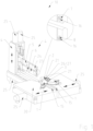
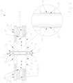
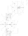
- Figure 1 as well as in Figure 14 An overview of the device 10 is shown, in which the profiles 1 to be joined can be seen, which are opposite each other with their joining surfaces 26, 27. The respective process steps are generally carried out on both profiles 1 simultaneously.
- the profile 1 in the present case is a profile element 1 made of thermoplastic material, e.g., PVC, for producing a window or door sash.
- the profile 1 is designed as an extruded profile with several parallel, transverse, and obliquely extending profile walls 28, the outermost border of which forms the profile edge 29.
- the profile 1 has, on the one hand, the lower 17 and the upper visible surface 18, and, on the other hand, functional surfaces that form the outer surfaces of the profile 1.
- the visible surfaces 17, 18 are the surfaces visible to the outside when the window or door is fully assembled.
- the functional surfaces are those surfaces required for the various functions of the window sash, such as the overlap that seals the window against the window frame, the support surface that supports a window pane inserted into the window, and other functional surfaces on which, for example, pane seals are arranged.
- Profile 1 is first cut to the profile cutting length, which is longer than the final dimension required for the joined profile 1 by the so-called burn-off.
- the so-called positioning step which can be part of the method according to the invention, is shown schematically.
- the respective profile 1 is pressed with its joining surface 26, 27 against a stop surface (not shown) of a profile stop in order to align the joining surface 26, 27 with the stop surface.
- the positioning of both profiles 1 can take place simultaneously if they are pressed against the stop surfaces of the profile stop in order to align the respective joining surfaces 26, 27 with respect to the profile stop and thus with a heating unit 4, as well as with each other.
- the profile part 1 is aligned with the profile stop, the profile 1 is clamped so tightly on the profile support 30 that no significant movement can occur between the profile 1 and the profile support 30 in the following steps.
- At least one limiting element in the form of a limiting knife 15 is arranged on the profile support 30, which is fixed to the outer surface of the profile part 1, here on the lower Figure 2 concealed visible surface 17, and thereby borders on the joining surface 26, 27 of the profile 1.
- the device 10 also has a heating unit 4 with at least two heating elements 5, 6, which are designed as heating mirrors, as shown in the Figures 1 to 8
- the two heating elements 5, 6 of the heating unit 4 can be moved and positioned horizontally and/or vertically by means of a servo motor 25, in particular the two heating elements 5, 6 can be moved towards each other and/or in the direction from the inner to the outer corner and/or from the outer to the inner corner of the joined profiles 1, as can be seen from Figure 1
- the horizontal and/or vertical movement of each heating element 5, 6 can be controlled independently.
- Each heating element 5, 6 has at least two heating plates or heating surfaces 23, 24, each of which is assigned to a joining surface 26, 27 of a profile end 2, 3 to be joined.
- the heating elements 5, 6 can be equipped with coated, preferably Teflon-coated, grooved, or toothed heating surfaces 23, 24, in particular on both sides.
- a tool in this case in the form of a cutting blade 7, 8 with preferably several cutting edges 16, is arranged on each heating element 5, 6, wherein a lower cutting blade 7 is assigned to the lower visible surface 17 of the profile end 2, 3 and an upper cutting blade 8 is assigned to the upper visible surface 18.
- the cutting blades 7, 8 can be heated in particular by means of the heating unit 4, which is the case in the present embodiment of the invention.
- the visible surfaces 17, 18 are machined at their respective profile edge layer 20, i.e. the profile ends 2, 3 are chamfered, preferably at least in the melting path along their visible surfaces 17, 18, and a chamfer is created towards the visible surface 17, 18.
- the outer profile edge layer 20 of the profile 1 is thus removed.
- the profile edge layer 20 can additionally contain the protective film or the decorative film of the profile 1 itself.
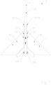
- Figure 2 shows the profile edge layer 20 in a detailed view.
- the removal depth 19 of the removed coating or the profile edge layer 20 on the profile 1, as seen in the mitre direction 21, ie the separation area line 32 preferably has the same dimension as at least the melting end path 31 during the melting process.
- other removal depths 19 and thus other separation area lines 32 are also conceivable, for example between the melting end point line 31 and the joining end point line 33, as can be seen from FIG. Fig. 13.2 emerges.
- the geometry of the mechanically removed chip is preferably designed as a slope, ie chamfer. This has the advantage that less material is removed, which leads to an increase in corner strength, since more material volume is available.
- the flow direction of the melt 9 is better aligned with the necessary direction, ie into the profile interior 11 or into the interior 12 of the profile chambers 13.
- the profile ends 2, 3 to be joined are fed to the heating unit 4, as shown in the Figures 5 to 8 is shown.
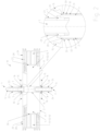
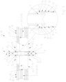
- Figure 5 shows the beginning, the Figures 6 and 7 the end of melting and the Figure 8 The end of the melting process with the profile supports 30 already opened.
- the joining surface 26, 27 of the profile 1 is pressed against the heating surfaces 23, 24 of the heating unit 4 in order to melt the profile 1 at its joining surface 26, 27.
- the respective profile supports 30 can be moved towards the heating unit 4, which was moved between the joining surfaces 26, 27 of the profile parts 1 after the profile stop was removed.
- the heating unit 4 is divided into several parts. This is because the heating elements 5, 6 move in such a way that the melt 9 is displaced into the profile interior 11 or into the interior 12 of the profile chambers 13 of the profiles 1. In this way, the melt 9 can be moved in a controlled manner from the visible surfaces 17, 18 inwards into the profile chambers 13.
- the heating unit 4 it is also conceivable for the heating unit 4 to consist of more than two heating elements in order to direct even more melt 9 into the inner chambers 12 in a targeted manner, for example from front to back, from back to front, from top to bottom and from bottom to top.
- the melting process includes the melting of profile 1 up to the melting end point, the post-heating, i.e. remaining at the melting end point to generate deep heat, i.e. heating of the material to be compressed. In this case, both are combined in the melting process, which is used to move the melt material 9 into the profile interior 11 or into the interior 12 of the profile chamber 13.
- the melting end path or the melting end point line 31 is drawn, which indicates the area up to which the heating unit 4 penetrates into the material of the profile 1 during the melting process.
- the material melted in the process escapes as melt excess or melt material 9 and is displaced into the profile interior 11 in a controlled manner by the heating mirror movements.
- Figure 3 shows the cutting process and Figure 5 the insertion of the heating unit 4.
- Figure 3 the separation area line 32 between the melting end path or the melting end point line 31 and the joining end point line 33 is drawn.
- the separation area line 32 indicates the point up to which the profile edge layer 20 is removed.
- the joining end point line 33 indicates the area up to which the profile 1 is compressed at its profile wall 28 during the subsequent joining step.
- the method can also be modified in such a way that the separation area line 32 and the melting end point line 31 coincide or that the joining end point line 33 and the separation area line 32 coincide.
- the Figure 2 arrangement shown in which the separation area line 32 is provided closer to the melting end point line 31 than to the joining end point line 33.
- a molding strip 14 acting as a finishing tool is shown.
- the melt 9 produced by the melting is moved into the profile interior 11 by the heating mirror movements.
- Form strip 14 is intended to prevent heated material from being pushed outwards during compression of the profiles 1.
- the molding 14 can also be seen.
- a controlled displacement of the melt excess or the melt material 9 into the profile interior 11 takes place using the multi-part heating unit 4.
- the heating elements 5, 6 are moved in such a way that the melt material 9 is displaced into the profile interior 11 or into the interior 12 of the profile chambers 13 of the profiles 1.
- the two profile parts 1 can be machined using a shaped strip 14.
- a two-stage post-processing is carried out, in which, during the upsetting process, the respective profile edge 29 is impressed with a direction of movement directed inwards towards the joining surface 26, 27, so that during the subsequent joining a V-groove is produced between the profile parts 1 in the area of the weld.
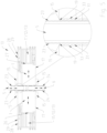
- Figure 12 with its detailed views shows different designs of this V-groove.
- the profile ends 2, 3 can be compressed against each other to join the profiles 1. It is also conceivable to compress the profile ends 2, 3 against each other without forming and/or displacing the melt 9 by means of the forming strip 14.
- Figure 9 shows the device shortly before the start of the upsetting process, Figure 10 an intermediate position and Figure 11 the end of the compression process.
- Figure 10 in particular the detailed view, shows that the contour, ie the bevels of the molding 14, touch the limiting blade 15, in particular its contour, ie the bevels, and thus close the path of the melt 9 to the outside.
- the design of the V-groove of the connection can be adjusted via the position, or more precisely the distance A, which can be adjusted independently of the profile supports 30, of the limiting blade 15 at the upsetting end, as can be seen from Figure 12
- the Figure 9 shows the position shortly before the start of joining or upsetting the profiles 1.
- the shaped strip 14 is positioned above or below the visible surface 17, 18 and is pushed up/down by the upsetting process via the bevels or undercut of the limiting blade 15.
- the area for the melt 9 is already blocked to the outside by the shaped strip 14, and no melt 9 can penetrate to the outside during the joining process.
- the heating unit 4 and its movements during the melting process move the melting material 9 in a controlled manner into the interior 12 of the profile chambers 13. To ensure that no contaminants from the area of the visible surfaces 17, 18 can enter the melting material 9, material and thus possible contaminants are removed from the surface of the profile 1 in the joining area.
- the contour of the forming strip 14 can shape the heated material between the melting end point and the joining end point during the upsetting process and, at the same time, it can prevent the melt 9 from escaping to the outside due to the positive engagement of the bevel of the forming strip 14 with the bevels of the limiting knives 15 and, depending on the limiting knife position at the upsetting end, contribute to the shaping.
- the limiting blade 15 can be guided under spring preload toward the joining surface 26, 27 in order to form the narrowest possible gap between the heating surface 23, 24 and the separating edge during the melting step.
- the limiting blade 15 can also be supplemented in its function by the shaping strip 14, which reduces the outward leakage of the melt material 9 during the melting step.
- the shaping strip 14 can be flush with the joining plane F.
Landscapes
- Engineering & Computer Science (AREA)
- Mechanical Engineering (AREA)
- Civil Engineering (AREA)
- Structural Engineering (AREA)
- Lining Or Joining Of Plastics Or The Like (AREA)
- Joining Of Corner Units Of Frames Or Wings (AREA)
Claims (15)
- Procédé de soudage d'au moins deux profilés (1) pour cadres ou battants de fenêtres ou de portes, avec les étapes suivantes :- la fourniture d'au moins deux profilés (1) qui sont reliés l'un à l'autre au niveau de surfaces d'assemblage (26, 27) des extrémités de profilé (2, 3),- le positionnement d'une unité de chauffage (4) avec au moins deux éléments chauffants (5, 6) entre les extrémités de profilé (2, 3) à assembler,- le chanfreinage, notamment l'enlèvement, d'une couche de bord de profilé (20) des extrémités de profilé (2, 3), de préférence au moins jusqu'à la course de fusion, le long de leurs surfaces visibles (17, 18) au moyen d'au moins un outil agencé sur les éléments chauffants (5, 6) de l'unité de chauffage (4), notamment au moyen d'au moins une lame de coupe (7, 8),- l'amenée des extrémités de profilé (2, 3) à assembler sur l'unité de chauffage (4),- la fusion des extrémités de profilé (2, 3) sur leurs surfaces d'assemblage ultérieures (26, 27) au moyen d'au moins une surface de chauffage (23, 24) agencée sur les éléments chauffants (5, 6),- le déplacement des éléments chauffants (5, 6) de telle sorte que la matière en fusion (9) est refoulée à l'intérieur du profilé (11) ou à l'intérieur (12) des chambres de profilé (13) du profilé (1),- le retrait de l'unité de chauffage (4) entre les extrémités de profilé à assembler (2, 3) et- la compression des extrémités de profilé (2, 3) l'une contre l'autre, de telle sorte que les profilés (1) sont assemblés entre eux.
- Procédé selon la revendication 1, caractérisé en ce qu'un déplacement relatif entre chaque élément chauffant (5, 6) et au moins une surface d'assemblage (26, 27) est effectué dans un plan d'assemblage (F) qui est essentiellement parallèle à l'au moins une surface d'assemblage (26, 27).
- Procédé selon la revendication 1 ou 2, caractérisé en ce que les deux éléments chauffants (5, 6) de l'unité de chauffage (4) sont déplacés et positionnés horizontalement et/ou verticalement, notamment en ce que les deux éléments chauffants (5, 6) sont déplacés l'un par rapport à l'autre et/ou dans la direction allant du coin intérieur au coin extérieur et/ou du coin extérieur au coin intérieur des profilés assemblés (1).
- Procédé selon l'une quelconque des revendications 1 à 3, caractérisé en ce que chaque élément chauffant (5, 6) présente au moins deux surfaces chauffantes (23, 24) associées chacune à une surface d'assemblage (26, 27) d'une extrémité de profilé (2, 3) à assembler.
- Procédé selon l'une quelconque des revendications précédentes, caractérisé en ce que le déplacement horizontal et/ou le déplacement vertical de chaque élément chauffant (5, 6) sont commandés indépendamment.
- Procédé selon l'une quelconque des revendications précédentes, caractérisé en ce qu'une lame de coupe (7, 8) avec de préférence plusieurs tranchants (16) est agencée sur chaque élément chauffant (5, 6), une lame de coupe inférieure (7) étant de préférence associée à la surface visible inférieure (17) de l'extrémité de profilé (2, 3) et une lame de coupe supérieure (8) étant de préférence associée à la surface visible supérieure (18).
- Procédé selon l'une quelconque des revendications précédentes, caractérisé en ce que la profondeur d'enlèvement (19) du revêtement ou de la couche de bord de profilé (20) enlevé(e) sur le profilé (1), vu dans la direction de l'onglet (21), possède au moins la même mesure que la course finale de fusion (31) lors du processus de fusion.
- Procédé selon l'une quelconque des revendications précédentes, caractérisé en ce que la couche de bord de profilé (20) est enlevée jusqu'à une ligne de zone de séparation (32) et une ligne de point final d'assemblage (33) caractérise la zone jusqu'à laquelle le profilé (1) est comprimé sur sa paroi de profilé (28) pendant l'étape d'assemblage et le profilé (1) est fondu jusqu'à une ligne de point final de fusion (31) et dans lequel la ligne de zone de séparation (32) et la ligne de point final de fusion (31) ou la ligne de zone de séparation (32) et la ligne de point final d'assemblage (33) coïncident ou la ligne de zone de séparation (32) se situe entre la ligne de point final de fusion (31) et la ligne de point final d'assemblage (33).
- Procédé selon l'une quelconque des revendications précédentes, caractérisé en ce que la lame de coupe (7, 8) est chauffée, notamment au moyen de l'unité de chauffage (4).
- Procédé selon l'une quelconque des revendications précédentes, caractérisé en ce que les éléments chauffants (5, 6) sont équipés de plaques chauffantes (23, 24) revêtues, de préférence téflonisées, striées et/ou dentées, notamment sur les deux côtés.
- Dispositif (10) pour le soudage d'au moins deux profilés (1) pour cadres ou battants de fenêtres ou de portes, notamment pour la mise en œuvre d'un procédé selon l'une quelconque des revendications 1 à 10, avec une unité de chauffage (4) pouvant être introduite entre les extrémités de profilé (2, 3) à assembler, avec au moins deux éléments de chauffage (5, 6) pour faire fondre les extrémités de profilé (2, 3) sur leurs surfaces d'assemblage ultérieures, dans lequel, pour le chanfreinage, notamment l'enlèvement, d'une couche de bord de profilé (20) des extrémités de profilé (2, 3) le long de leurs surfaces visibles (17, 18), il est prévu au moins un outil agencé sur les éléments chauffants (5, 6) de l'unité de chauffage (4), notamment au moins une lame de coupe (7, 8), les éléments chauffants (5, 6) pouvant être déplacés de telle sorte que la matière en fusion (9) est refoulée à l'intérieur du profilé (11) ou à l'intérieur (12) des chambres de profilé (13), un dispositif de compression étant prévu pour comprimer les extrémités de profilé (2, 3).
- Dispositif (10) selon la revendication 11, caractérisé en ce que les éléments chauffants (5, 6) peuvent être déplacés et positionnés horizontalement et/ou verticalement au moyen de servomoteurs (25), notamment en ce que les deux éléments chauffants (5, 6) peuvent être déplacés l'un par rapport à l'autre et/ou dans la direction allant du coin intérieur vers le coin extérieur et/ou du coin extérieur vers le coin intérieur des profilés assemblés (1).
- Dispositif (10) selon la revendication 11 ou 12, caractérisé en ce qu'une lame de coupe (7, 8) avec de préférence plusieurs tranchants (16) est agencée sur chaque élément chauffant (5, 6), une lame de coupe inférieure (7) étant de préférence associée à la surface visible inférieure (17) de l'extrémité de profilé (2, 3) et une lame de coupe supérieure (8) étant de préférence associée à la surface visible supérieure (18).
- Dispositif (10) selon les revendications 11 à 13, caractérisé en ce que les éléments chauffants (5, 6) sont équipés de surfaces chauffantes (23, 24) revêtues, de préférence téflonisées, striées ou dentées, notamment des deux côtés.
- Dispositif (10) selon l'une quelconque des revendications 11 à 14, caractérisé en ce que l'outil (7, 8) est chauffé, notamment au moyen de l'unité de chauffage (4).
Applications Claiming Priority (2)
| Application Number | Priority Date | Filing Date | Title |
|---|---|---|---|
| DE102020123272.1A DE102020123272B3 (de) | 2020-09-07 | 2020-09-07 | Verfahren und Vorrichtung zum Verschweißen von wenigstens zwei Profilen für Fenster- oder Türrahmen bzw. -flügeln |
| PCT/EP2021/072354 WO2022048872A1 (fr) | 2020-09-07 | 2021-08-11 | Procédé et dispositif destiné au soudage d'au moins deux sections profilées servant aux cadres de fenêtre ou de porte ou aux feuillages |
Publications (2)
| Publication Number | Publication Date |
|---|---|
| EP4210932A1 EP4210932A1 (fr) | 2023-07-19 |
| EP4210932B1 true EP4210932B1 (fr) | 2025-06-04 |
Family
ID=77543488
Family Applications (1)
| Application Number | Title | Priority Date | Filing Date |
|---|---|---|---|
| EP21762655.5A Active EP4210932B1 (fr) | 2020-09-07 | 2021-08-11 | Procédé et dispositif destiné au soudage d'au moins deux sections profilées servant aux cadres de fenêtre ou de porte ou aux battants |
Country Status (7)
| Country | Link |
|---|---|
| US (2) | US12188295B2 (fr) |
| EP (1) | EP4210932B1 (fr) |
| CA (1) | CA3191810A1 (fr) |
| DE (1) | DE102020123272B3 (fr) |
| ES (1) | ES3034263T3 (fr) |
| PL (1) | PL4210932T3 (fr) |
| WO (1) | WO2022048872A1 (fr) |
Families Citing this family (3)
| Publication number | Priority date | Publication date | Assignee | Title |
|---|---|---|---|---|
| IT202300005184A1 (it) * | 2023-03-20 | 2024-09-20 | Graf Synergy Srl | Piastra per dispositivi scaldanti di macchine per la lavorazione di profilati in materiale plastico |
| GB2640405A (en) * | 2024-04-15 | 2025-10-22 | Kaban Makina Sanayi Ve Ticaret Ltd Sirketi | Welding device for PVC profiles |
| PL132107U1 (pl) * | 2024-04-19 | 2025-10-20 | Kaban Makina Sanayi Ve Ticaret Limited Sirketi | Urządzenie zgrzewające do profili z PCW |
Citations (1)
| Publication number | Priority date | Publication date | Assignee | Title |
|---|---|---|---|---|
| DE2009992A1 (en) * | 1970-03-04 | 1971-09-16 | Hassler & Sommer | Turret head plastic welding machine |
Family Cites Families (21)
| Publication number | Priority date | Publication date | Assignee | Title |
|---|---|---|---|---|
| US2387566A (en) * | 1940-08-22 | 1945-10-23 | Custers Jakob | Apparatus for connecting plies of thermoplastic material |
| DE2312362B2 (de) | 1973-03-13 | 1976-01-02 | Dynamit Nobel Ag, 5210 Troisdorf | Zusatzeinrichtung für eine Schweißmaschine zum Verschweißen und Entgraten von Kunststoffprofilen |
| DE3634793A1 (de) * | 1986-10-11 | 1988-04-14 | Urban Maschinenbau | Verfahren zum verschweissen von kunststoffprofilen |
| AT512088A1 (de) * | 2011-11-07 | 2013-05-15 | Fux Maschb U Kunststofftechnik Gmbh | Verfahren und vorrichtung zur verbindung von dichtungsprofilen |
| DE102012112533A1 (de) | 2012-01-10 | 2013-07-11 | Rotox Besitz-Und Verwaltungsgesellschaft Mbh | Verfahren und Vorrichtung zum Verschweißen von faserverstärkten Profilteilen |
| DE202013012778U1 (de) | 2012-03-07 | 2019-07-31 | Graf Synergy S.R.L. | Vorrichtung zum Verschweißen von profilierten Elementen aus Kunststoffmaterial, insbesondere PVC |
| JP5927264B2 (ja) | 2014-10-17 | 2016-06-01 | ファナック株式会社 | 射出成形システム |
| DE102015000908A1 (de) | 2015-01-23 | 2016-07-28 | Liebherr-Verzahntechnik Gmbh | Verfahren und Vorrichtung zur Verzahnbearbeitung eines Werkstückes durch ein Diagonalwälzverfahren |
| DE202015000908U1 (de) | 2015-02-04 | 2015-03-04 | Stürtz Maschinenbau GmbH | Schweißvorrichtung |
| DE102015107121B4 (de) | 2015-05-07 | 2019-11-14 | Rotox Besitz-Und Verwaltungsgesellschaft Mbh | Verfahren und Vorrichtung zum Verbinden von Profilteilen |
| ITUB20152125A1 (it) | 2015-07-13 | 2017-01-13 | Graf Synergy Srl | Macchina per la saldatura di profilati in plastica |
| DE102015013439B4 (de) * | 2015-10-15 | 2022-10-13 | Stürtz Maschinenbau GmbH | Verfahren und Vorrichtung zum Verschweißen von Profilstäben aus Kunststoff |
| DE102015014439A1 (de) | 2015-11-07 | 2017-05-11 | Dynamics Gesellschaft für Umweltschutz und biologische Verfahrenstechnik mbH & Co. KG | Öffnungsbegrenzer zur Lärmverminderung beim Öffnen von Mülltonnen |
| DE102016102240A1 (de) | 2016-02-10 | 2017-08-10 | Rotox Besitz-Und Verwaltungsgesellschaft Mbh | Vorrichtung zum Verbinden von Profilstücken |
| DE102016104785A1 (de) | 2016-03-15 | 2017-09-21 | Rotox Besitz-Und Verwaltungsgesellschaft Mbh | Vorrichtung und Verfahren zum Verbinden von Profilteilen |
| KR102033815B1 (ko) * | 2016-03-25 | 2019-10-17 | (주)엘지하우시스 | 창호프레임 제조용 열 융착장치 |
| DE102016125483A1 (de) * | 2016-12-22 | 2018-06-28 | Rotox Besitz-Und Verwaltungsgesellschaft Mbh | Verfahren und Vorrichtung zum Verbinden von Kunststoffprofilteilen |
| ES2964966T3 (es) | 2017-05-18 | 2024-04-10 | Hendrik Soenen | Procedimiento y dispositivo para soldar al menos dos perfiles |
| DE102017127483A1 (de) * | 2017-11-21 | 2019-05-23 | Rotox Besitz-Und Verwaltungsgesellschaft Mbh | Vorrichtung und Verfahren zum Verbinden von Profilteilen |
| IT201800002154A1 (it) | 2018-01-30 | 2019-07-30 | Emmegi Spa | Apparato per saldare barre profilate. |
| DE102018133638A1 (de) | 2018-12-27 | 2020-07-02 | Urban Gmbh & Co. Maschinenbau Kg | Verfahren und Vorrichtung für das Verschweißen von Profilstäben |
-
2020
- 2020-09-07 DE DE102020123272.1A patent/DE102020123272B3/de active Active
-
2021
- 2021-08-11 ES ES21762655T patent/ES3034263T3/es active Active
- 2021-08-11 US US18/043,060 patent/US12188295B2/en active Active
- 2021-08-11 WO PCT/EP2021/072354 patent/WO2022048872A1/fr not_active Ceased
- 2021-08-11 EP EP21762655.5A patent/EP4210932B1/fr active Active
- 2021-08-11 CA CA3191810A patent/CA3191810A1/fr active Pending
- 2021-08-11 PL PL21762655.5T patent/PL4210932T3/pl unknown
-
2024
- 2024-10-31 US US18/932,764 patent/US20250059821A1/en active Pending
Patent Citations (1)
| Publication number | Priority date | Publication date | Assignee | Title |
|---|---|---|---|---|
| DE2009992A1 (en) * | 1970-03-04 | 1971-09-16 | Hassler & Sommer | Turret head plastic welding machine |
Also Published As
| Publication number | Publication date |
|---|---|
| CA3191810A1 (fr) | 2022-03-10 |
| PL4210932T3 (pl) | 2025-08-18 |
| EP4210932A1 (fr) | 2023-07-19 |
| US20230313600A1 (en) | 2023-10-05 |
| WO2022048872A1 (fr) | 2022-03-10 |
| DE102020123272B3 (de) | 2021-10-21 |
| ES3034263T3 (en) | 2025-08-14 |
| US12188295B2 (en) | 2025-01-07 |
| US20250059821A1 (en) | 2025-02-20 |
Similar Documents
| Publication | Publication Date | Title |
|---|---|---|
| EP4210932B1 (fr) | Procédé et dispositif destiné au soudage d'au moins deux sections profilées servant aux cadres de fenêtre ou de porte ou aux battants | |
| EP3697599B1 (fr) | Dispositif et procédé pour relier des pièces profilées | |
| DE102015107121B4 (de) | Verfahren und Vorrichtung zum Verbinden von Profilteilen | |
| DE2312362A1 (de) | Verfahren und vorrichtung zum verschweissen und entgraten von kunststoffprofilen | |
| WO2017137467A1 (fr) | Dispositif pour relier des pièces profilées | |
| DE10306524A1 (de) | Vorrichtung und Verfahren zum Schweißen von Kunststoffprofilen | |
| DE3039733A1 (de) | Verfahren zum stumpfverschweissen von thermoplastischen kunststoff-hohlprofilstaeben und vorrichtung zu dessen durchfuehrung | |
| EP2190646B1 (fr) | Procédé et dispositif de soudage de barres profilées en plastique | |
| DE102019109294B4 (de) | Verfahren zum Verschweißen von Profilstäben | |
| EP3339006A1 (fr) | Procédé et dispositif de raccordement des pièces profilées en matière plastique | |
| DE2035308A1 (de) | Verfahren und Vorrichtung zur Her stellung von stumpfgeschweißten Rahmen aus Kunststoff oder Leichtmetall Profilschienen | |
| EP3795339B1 (fr) | Élément chauffant pour chauffer des profilés en plastique et procédé d'enlèvement de matière à l'extérieur de la zone de soudage | |
| EP3414078A1 (fr) | Procédé et dispositif pour relier des pièces profilées | |
| DE19918427A1 (de) | Vorrichtung und Maschine für das Abtrennen bzw. Bearbeiten eines Schweißwulstes an Kunststoffprofilen | |
| EP0349474B1 (fr) | Méthode d'assemblage d'angle ou en T de profilés creux en matière plastique pour fenêtres ou portes | |
| DE3408373A1 (de) | Verfahren und vorrichtung zur herstellung von eckverbindungen in rahmen aus thermoplastischen, insbesondere hart-pvc-profilen fuer fluegel und rahmen von verglasten tueren und fenstern | |
| DE19739252B4 (de) | Verfahren zum Bearbeiten von zu verschweißenden Hohlkammerprofilen mit Gummidichtung | |
| EP3672786B1 (fr) | Procédé et dispositif pour relier des pièces profilées | |
| EP1136233B1 (fr) | Dispositif de soudage de barres profilées en matière plastique | |
| EP4667194A1 (fr) | Dispositif et procédé de fabrication d'une liaison profilée | |
| WO2024115564A1 (fr) | Méthode et dispositif de production d'une liaison entre des profilés extrudés | |
| EP3575068B1 (fr) | Dispositif et procédé de raccordement de pièces profilées | |
| DE3146660C2 (de) | Verfahren zum Verbinden von Profilen aus Kunststoff | |
| EP4520510A1 (fr) | Procede de soudage de barres profilees |
Legal Events
| Date | Code | Title | Description |
|---|---|---|---|
| STAA | Information on the status of an ep patent application or granted ep patent |
Free format text: STATUS: UNKNOWN |
|
| STAA | Information on the status of an ep patent application or granted ep patent |
Free format text: STATUS: THE INTERNATIONAL PUBLICATION HAS BEEN MADE |
|
| PUAI | Public reference made under article 153(3) epc to a published international application that has entered the european phase |
Free format text: ORIGINAL CODE: 0009012 |
|
| STAA | Information on the status of an ep patent application or granted ep patent |
Free format text: STATUS: REQUEST FOR EXAMINATION WAS MADE |
|
| 17P | Request for examination filed |
Effective date: 20230131 |
|
| AK | Designated contracting states |
Kind code of ref document: A1 Designated state(s): AL AT BE BG CH CY CZ DE DK EE ES FI FR GB GR HR HU IE IS IT LI LT LU LV MC MK MT NL NO PL PT RO RS SE SI SK SM TR |
|
| DAV | Request for validation of the european patent (deleted) | ||
| DAX | Request for extension of the european patent (deleted) | ||
| P01 | Opt-out of the competence of the unified patent court (upc) registered |
Effective date: 20240405 |
|
| STAA | Information on the status of an ep patent application or granted ep patent |
Free format text: STATUS: EXAMINATION IS IN PROGRESS |
|
| 17Q | First examination report despatched |
Effective date: 20240801 |
|
| RIC1 | Information provided on ipc code assigned before grant |
Ipc: E06B 3/96 20060101ALI20241206BHEP Ipc: E06B 3/22 20060101ALI20241206BHEP Ipc: B29C 65/20 20060101AFI20241206BHEP |
|
| GRAP | Despatch of communication of intention to grant a patent |
Free format text: ORIGINAL CODE: EPIDOSNIGR1 |
|
| STAA | Information on the status of an ep patent application or granted ep patent |
Free format text: STATUS: GRANT OF PATENT IS INTENDED |
|
| INTG | Intention to grant announced |
Effective date: 20250207 |
|
| GRAS | Grant fee paid |
Free format text: ORIGINAL CODE: EPIDOSNIGR3 |
|
| GRAA | (expected) grant |
Free format text: ORIGINAL CODE: 0009210 |
|
| STAA | Information on the status of an ep patent application or granted ep patent |
Free format text: STATUS: THE PATENT HAS BEEN GRANTED |
|
| AK | Designated contracting states |
Kind code of ref document: B1 Designated state(s): AL AT BE BG CH CY CZ DE DK EE ES FI FR GB GR HR HU IE IS IT LI LT LU LV MC MK MT NL NO PL PT RO RS SE SI SK SM TR |
|
| REG | Reference to a national code |
Ref country code: GB Ref legal event code: FG4D Free format text: NOT ENGLISH |
|
| REG | Reference to a national code |
Ref country code: CH Ref legal event code: EP |
|
| REG | Reference to a national code |
Ref country code: DE Ref legal event code: R096 Ref document number: 502021007671 Country of ref document: DE |
|
| REG | Reference to a national code |
Ref country code: IE Ref legal event code: FG4D Free format text: LANGUAGE OF EP DOCUMENT: GERMAN |
|
| REG | Reference to a national code |
Ref country code: NL Ref legal event code: FP |
|
| REG | Reference to a national code |
Ref country code: ES Ref legal event code: FG2A Ref document number: 3034263 Country of ref document: ES Kind code of ref document: T3 Effective date: 20250814 |
|
| PGFP | Annual fee paid to national office [announced via postgrant information from national office to epo] |
Ref country code: NL Payment date: 20250821 Year of fee payment: 5 |
|
| PG25 | Lapsed in a contracting state [announced via postgrant information from national office to epo] |
Ref country code: FI Free format text: LAPSE BECAUSE OF FAILURE TO SUBMIT A TRANSLATION OF THE DESCRIPTION OR TO PAY THE FEE WITHIN THE PRESCRIBED TIME-LIMIT Effective date: 20250604 |
|
| PGFP | Annual fee paid to national office [announced via postgrant information from national office to epo] |
Ref country code: ES Payment date: 20250926 Year of fee payment: 5 |
|
| PGFP | Annual fee paid to national office [announced via postgrant information from national office to epo] |
Ref country code: DE Payment date: 20250831 Year of fee payment: 5 |
|
| REG | Reference to a national code |
Ref country code: LT Ref legal event code: MG9D |
|
| PG25 | Lapsed in a contracting state [announced via postgrant information from national office to epo] |
Ref country code: NO Free format text: LAPSE BECAUSE OF FAILURE TO SUBMIT A TRANSLATION OF THE DESCRIPTION OR TO PAY THE FEE WITHIN THE PRESCRIBED TIME-LIMIT Effective date: 20250904 |
|
| PGFP | Annual fee paid to national office [announced via postgrant information from national office to epo] |
Ref country code: IT Payment date: 20250929 Year of fee payment: 5 Ref country code: PL Payment date: 20250731 Year of fee payment: 5 |
|
| PG25 | Lapsed in a contracting state [announced via postgrant information from national office to epo] |
Ref country code: BG Free format text: LAPSE BECAUSE OF FAILURE TO SUBMIT A TRANSLATION OF THE DESCRIPTION OR TO PAY THE FEE WITHIN THE PRESCRIBED TIME-LIMIT Effective date: 20250604 |
|
| PGFP | Annual fee paid to national office [announced via postgrant information from national office to epo] |
Ref country code: BE Payment date: 20250820 Year of fee payment: 5 Ref country code: GB Payment date: 20250821 Year of fee payment: 5 |
|
| PG25 | Lapsed in a contracting state [announced via postgrant information from national office to epo] |
Ref country code: HR Free format text: LAPSE BECAUSE OF FAILURE TO SUBMIT A TRANSLATION OF THE DESCRIPTION OR TO PAY THE FEE WITHIN THE PRESCRIBED TIME-LIMIT Effective date: 20250604 |
|
| PGFP | Annual fee paid to national office [announced via postgrant information from national office to epo] |
Ref country code: FR Payment date: 20250828 Year of fee payment: 5 Ref country code: AT Payment date: 20251020 Year of fee payment: 5 |
|
| PG25 | Lapsed in a contracting state [announced via postgrant information from national office to epo] |
Ref country code: RS Free format text: LAPSE BECAUSE OF FAILURE TO SUBMIT A TRANSLATION OF THE DESCRIPTION OR TO PAY THE FEE WITHIN THE PRESCRIBED TIME-LIMIT Effective date: 20250904 |
|
| PG25 | Lapsed in a contracting state [announced via postgrant information from national office to epo] |
Ref country code: LV Free format text: LAPSE BECAUSE OF FAILURE TO SUBMIT A TRANSLATION OF THE DESCRIPTION OR TO PAY THE FEE WITHIN THE PRESCRIBED TIME-LIMIT Effective date: 20250604 |
|
| PG25 | Lapsed in a contracting state [announced via postgrant information from national office to epo] |
Ref country code: PT Free format text: LAPSE BECAUSE OF FAILURE TO SUBMIT A TRANSLATION OF THE DESCRIPTION OR TO PAY THE FEE WITHIN THE PRESCRIBED TIME-LIMIT Effective date: 20251006 |
|
| PG25 | Lapsed in a contracting state [announced via postgrant information from national office to epo] |
Ref country code: IS Free format text: LAPSE BECAUSE OF FAILURE TO SUBMIT A TRANSLATION OF THE DESCRIPTION OR TO PAY THE FEE WITHIN THE PRESCRIBED TIME-LIMIT Effective date: 20251004 |
|
| PG25 | Lapsed in a contracting state [announced via postgrant information from national office to epo] |
Ref country code: SM Free format text: LAPSE BECAUSE OF FAILURE TO SUBMIT A TRANSLATION OF THE DESCRIPTION OR TO PAY THE FEE WITHIN THE PRESCRIBED TIME-LIMIT Effective date: 20250604 |
|
| PG25 | Lapsed in a contracting state [announced via postgrant information from national office to epo] |
Ref country code: CZ Free format text: LAPSE BECAUSE OF FAILURE TO SUBMIT A TRANSLATION OF THE DESCRIPTION OR TO PAY THE FEE WITHIN THE PRESCRIBED TIME-LIMIT Effective date: 20250604 |
|
| PG25 | Lapsed in a contracting state [announced via postgrant information from national office to epo] |
Ref country code: EE Free format text: LAPSE BECAUSE OF FAILURE TO SUBMIT A TRANSLATION OF THE DESCRIPTION OR TO PAY THE FEE WITHIN THE PRESCRIBED TIME-LIMIT Effective date: 20250604 |
|
| PG25 | Lapsed in a contracting state [announced via postgrant information from national office to epo] |
Ref country code: SK Free format text: LAPSE BECAUSE OF FAILURE TO SUBMIT A TRANSLATION OF THE DESCRIPTION OR TO PAY THE FEE WITHIN THE PRESCRIBED TIME-LIMIT Effective date: 20250604 |
|
| REG | Reference to a national code |
Ref country code: DE Ref legal event code: R097 Ref document number: 502021007671 Country of ref document: DE |
|
| PG25 | Lapsed in a contracting state [announced via postgrant information from national office to epo] |
Ref country code: RO Free format text: LAPSE BECAUSE OF FAILURE TO SUBMIT A TRANSLATION OF THE DESCRIPTION OR TO PAY THE FEE WITHIN THE PRESCRIBED TIME-LIMIT Effective date: 20250604 |
|
| REG | Reference to a national code |
Ref country code: CH Ref legal event code: H13 Free format text: ST27 STATUS EVENT CODE: U-0-0-H10-H13 (AS PROVIDED BY THE NATIONAL OFFICE) Effective date: 20260324 |
|
| PG25 | Lapsed in a contracting state [announced via postgrant information from national office to epo] |
Ref country code: MC Free format text: LAPSE BECAUSE OF FAILURE TO SUBMIT A TRANSLATION OF THE DESCRIPTION OR TO PAY THE FEE WITHIN THE PRESCRIBED TIME-LIMIT Effective date: 20250604 |
|
| PLBE | No opposition filed within time limit |
Free format text: ORIGINAL CODE: 0009261 |
|
| STAA | Information on the status of an ep patent application or granted ep patent |
Free format text: STATUS: NO OPPOSITION FILED WITHIN TIME LIMIT |
|
| PG25 | Lapsed in a contracting state [announced via postgrant information from national office to epo] |
Ref country code: DK Free format text: LAPSE BECAUSE OF FAILURE TO SUBMIT A TRANSLATION OF THE DESCRIPTION OR TO PAY THE FEE WITHIN THE PRESCRIBED TIME-LIMIT Effective date: 20250604 |
|
| PG25 | Lapsed in a contracting state [announced via postgrant information from national office to epo] |
Ref country code: LU Free format text: LAPSE BECAUSE OF NON-PAYMENT OF DUE FEES Effective date: 20250811 |
|
| REG | Reference to a national code |
Ref country code: CH Ref legal event code: L10 Free format text: ST27 STATUS EVENT CODE: U-0-0-L10-L00 (AS PROVIDED BY THE NATIONAL OFFICE) Effective date: 20260416 |
|
| PG25 | Lapsed in a contracting state [announced via postgrant information from national office to epo] |
Ref country code: CH Free format text: LAPSE BECAUSE OF NON-PAYMENT OF DUE FEES Effective date: 20250831 |