EP4212039B1 - Dispositif de génération d'aérosol, procédé de chauffage d'un article à fumer et système de génération d'aérosol - Google Patents
Dispositif de génération d'aérosol, procédé de chauffage d'un article à fumer et système de génération d'aérosol Download PDFInfo
- Publication number
- EP4212039B1 EP4212039B1 EP23161447.0A EP23161447A EP4212039B1 EP 4212039 B1 EP4212039 B1 EP 4212039B1 EP 23161447 A EP23161447 A EP 23161447A EP 4212039 B1 EP4212039 B1 EP 4212039B1
- Authority
- EP
- European Patent Office
- Prior art keywords
- aerosol
- heater
- smoking article
- period
- generation device
- Prior art date
- Legal status (The legal status is an assumption and is not a legal conclusion. Google has not performed a legal analysis and makes no representation as to the accuracy of the status listed.)
- Active
Links
Images



Classifications
-
- A—HUMAN NECESSITIES
- A24—TOBACCO; CIGARS; CIGARETTES; SIMULATED SMOKING DEVICES; SMOKERS' REQUISITES
- A24F—SMOKERS' REQUISITES; MATCH BOXES; SIMULATED SMOKING DEVICES
- A24F40/00—Electrically operated smoking devices; Component parts thereof; Manufacture thereof; Maintenance or testing thereof; Charging means specially adapted therefor
- A24F40/50—Control or monitoring
- A24F40/57—Temperature control
-
- A—HUMAN NECESSITIES
- A24—TOBACCO; CIGARS; CIGARETTES; SIMULATED SMOKING DEVICES; SMOKERS' REQUISITES
- A24F—SMOKERS' REQUISITES; MATCH BOXES; SIMULATED SMOKING DEVICES
- A24F40/00—Electrically operated smoking devices; Component parts thereof; Manufacture thereof; Maintenance or testing thereof; Charging means specially adapted therefor
- A24F40/50—Control or monitoring
-
- A—HUMAN NECESSITIES
- A24—TOBACCO; CIGARS; CIGARETTES; SIMULATED SMOKING DEVICES; SMOKERS' REQUISITES
- A24F—SMOKERS' REQUISITES; MATCH BOXES; SIMULATED SMOKING DEVICES
- A24F40/00—Electrically operated smoking devices; Component parts thereof; Manufacture thereof; Maintenance or testing thereof; Charging means specially adapted therefor
- A24F40/20—Devices using solid inhalable precursors
Definitions
- the present invention relates to an aerosol generation device, a method for heating a smoking article and an aerosol generation system.
- Patent Literature 1 and Patent Literature 2 A non-combustion-type aerosol generation device, which is used in place of a prior-art combustion-type cigarette, for sucking aerosol generated by atomizing an aerosol forming base-material (a smoking article) by a heater has been known (Patent Literature 1 and Patent Literature 2).
- Patent Literature 1 discloses an aerosol generation device which comprises a smoking article comprising a solid aerosol forming base-material, and a blade-type heater that is to be inserted in the aerosol forming base-material when it is used. The heater heats the aerosol forming base-material from the inside thereof.
- Patent Literature 2 discloses an aerosol generation device which comprises a smoking article comprising a solid aerosol forming base-material, and a cylinder-type heater that is to be positioned in an outer periphery part of the aerosol forming base-material when it is used. The heater heats the aerosol forming base-material from the outer periphery side.
- EP 3 062 644 A2 relates to an apparatus to heat smokable material to volatilise at least one component of the smokable material.
- the apparatus has a housing and a plurality of heater segments longitudinally arranged within the housing for heating smokable material contained within the apparatus. At least one heater segment is arranged so as to heat smokable material contained within the at least one heater segment more quickly than at least one other heater segment heats smokable material contained within the at least one other heater segment.
- a user can easily recognize a specific stage, i.e., one of an initial period, an intermediate period, and a final period of a suction allowable period, that the user is presently in, by visually recognizing a position of the cigarette where the cigarette is burning.
- a specific stage i.e., one of an initial period, an intermediate period, and a final period of a suction allowable period
- the delivery profile of main aerosol components described in Patent Literature 1 exhibits increase in an initial period of operation of a heater, and, thereafter, maintains the delivery profile in a constant state until the heater is stopped.
- a specific period i.e., one of an initial period, an intermediate period, and a final period of a suction allowable period, that the user is presently in.
- a heater which is constructed to be able to heat an outer periphery of a smoking article comprising an aerosol source, is controlled in such a manner that a delivery profile of aerosol in a predetermined suction allowable period comprises one or plural maximum values in a period between a start point and an end point in the suction allowable period.
- the delivery profile of aerosol increases first, has a maximum value thereafter, and decreases thereafter.
- a user can recognize a specific period, i.e., one of an initial period, an intermediate period, and a final period of a suction allowable period, that the user is presently in, based on sensation felt when sucking aerosol.
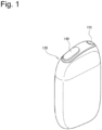
- Fig. 1 is a figure showing a flavor inhaler according to an embodiment.
- Fig. 2 is a figure showing the flavor inhaler in which a smoking article is inserted.
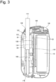
- Fig. 3 is a figure showing an internal construction of the flavor inhaler shown in Fig. 2 .
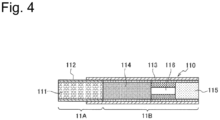
- Fig. 4 is a figure showing an internal construction of the smoking article shown in Fig. 2 .
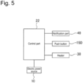
- Fig. 5 is a block diagram of the flavor inhaler.
- the flavor inhaler 100 may be a non-combustion-type flavor inhaler for generating, without a combustion process, aerosol from a smoking article.
- the flavor inhaler 100 may be a portable device.
- the flavor inhaler 100 comprises a smoking article 110 including an aerosol source, and an aerosol generation device 120 for generating aerosol from the smoking article 110.
- the smoking article 110 is an exchangeable cartridge which may include an aerosol source and a flavor source, and has a column shape extending in a longitudinal direction.
- the smoking article 110 may be constructed to generates aerosol and flavor components when it is heated in the state that it is inserted in the aerosol generation device 120.
- the smoking article 110 comprises a base material part 11A, which comprises a filling article 111 and first rolling paper 112 by which the filling article 111 is wound, and a suction opening part 11B which forms an end part opposite to the base material part 11A.
- the base material part 11A and the suction opening part 11B are connected by second rolling paper 113 which is different from the first rolling paper 112.
- the suction opening part 11B in Fig. 4 comprises a paper tube part 114, a filter part 115, a hollow segment part 116 positioned between the paper tube part 114 and the filter part 115.
- the hollow segment part 116 comprises a filling layer including one or plural hollow channels, and a plug wrapper for covering the filling layer. Since the density of filled fibers in the filling layer is high, air and aerosol flows through the hollow channel only, and almost no air and aerosol flows through the filling layer, when suction action is performed.
- the flavor generation article 110 if it is desired to lower a decrease in the quantity of the aerosol components due to filtering in the filter part 115, it is effective to shorten the length of the filter part 115 and replace that part by the hollow segment part 116, for increasing the quantity of delivery of the aerosol.
- the suction opening part 11B in Fig. 4 is constructed by using three segments; however, in the present embodiment, the suction opening part 11B may be constructed by using one or two segments, or may be constructed by using four or more segments. For example, it is possible to omit the hollow segment part 116, and form the suction opening part 11B by arranging the paper tube part 114 and the filter part 115 adjacent to each other.
- the length in the longitudinal direction of the smoking article 110 it is preferable to set it to 40-90 mm, more preferable to set it to 50-75 mm, and still more preferably to set it to 50-60 mm.
- the circumference of the smoking article 110 it is preferable to set it to 15-25 mm, more preferable to set it to 17-24 mm, and still more preferably to set it to 20-23 mm.
- the length of the base material part 11A may be 20 mm
- the length of the first rolling paper 112 may be 20 mm
- the length of the hollow segment part 116 may be 8 mm
- the length of the filter part 115 may be 7 mm; however, the length of each of the above segments may be changed appropriately, according to suitability to manufacture, required quality, and so on.
- the filling article 111 in the smoking article 110 may comprise an aerosol source which generates aerosol when heat of predetermined temperature is applied thereto.
- the kind of the aerosol source is not specifically limited, and extracted material and/or components thereof, that are obtained from various natural products, may be selected as an aerosol source according to a use. Glycerin, propylene glycol, triacetin, 1,3-butanediol, and a mixture thereof, for example, can be listed as aerosol sources.
- the aerosol source content of the filling article 111 is not specifically limited; and, in view of generation of sufficient quantity of aerosol and satisfactory addition of fragrance inhaling taste, the aerosol source content is usually equal to or greater than 5 weight percent, and, preferably, equal to or greater than 10 weight percent, and is usually equal to or less than 50 weight percent, and, preferably, equal to or less than 20 weight percent.
- the filling article 111 in the smoking article 110 in the present embodiment may comprise shredded tobacco as a flavor source.
- the material of shredded tobacco is not specifically limited, and publicly known material such as a lamina, a stem, and so on may be used as the material.
- the range of the content of the filling article 111 in the smoking article 110, in the case that the circumference is 22 mm and the length is 20 mm, is, for example, 200-400 mg, and, preferably, 250-320 mg.
- the water content of the filling article 111 is, for example, 8-18 weight percent, and, preferably, 10-16 weight percent.
- the water content is that explained above, occurrence of staining at the time of rolling is suppressed, and suitability to rolling at the time of manufacture of the base part 11A is made satisfactory.
- the size, the preparation method, and so on of the shredded tobacco used as the filling article 111 There is no special limitation with respect to the size, the preparation method, and so on of the shredded tobacco used as the filling article 111.
- dried tobacco leaves cut into pieces, each having the width of 0.8-1.2 mm may be used.
- dried tobacco leaves are crushed and uniformized to become particles, regarding which the average particle size is 20-200 ⁇ m, and the particles are processed to become a sheet, and the sheet cut into pieces, each having the width of 0.8-1.2 mm, may be used.
- the above sheet formed via the sheet process may be processed to gather it, and the gathered sheet may be used as the filling article 111.
- the filling article 111 may comprise one kind or two or more kinds of flavors.
- the kinds of flavors are not specifically limited; however, in view of provision of satisfactory smoke flavor, a flavor is menthol, preferably.
- each sheet of the first and second rolling paper 112 and 113 may be constructed by use of base paper which has the basis weight of, for example, 20-65 gsm, and, preferably, 25-45 gsm.
- the thickness of each sheet of the first and second rolling paper 112 and 113 is not specifically limited; however, in view of rigidness, gas permeability, and easiness of adjustment at the time of paper manufacture, the thickness is set to 10-100 ⁇ m, and, preferably, set to 20-75 ⁇ m, and, more preferably, set to 30-50 ⁇ m.
- filler may be included in the rolling paper 112 and 113 in the filling article 111.
- the filler content may be equal to or greater than 10 weight percent and less than 60 weight percent, and, preferably, 15-45 weigh percent, with respect to the total weight of the rolling paper 112 and 113.
- basis weight 25-45 gsm
- paper including filler such as that explained above presents a white color that is preferable in view of appearance of paper used as rolling paper of the smoking article 110, and is able to keep its whiteness permanently.
- the ISO whiteness of rolling paper can be raised to 83 % or more, for example.
- the rolling paper 112 and 113 have the tensile strength of 8N/15mm or more.
- the tensile strength can be increased by reducing the filler content. Specifically, the tensile strength can be increased by reducing the filler content to that less than the upper limit of the filler content that has been shown with respect to each range of the basis weight illustrated in the above description.
- Fig. 3 is referred to; and the aerosol generation device 120 comprises an insertion hole 130 to which the smoking article 110 can be inserted. That is, the aerosol generation device 120 comprises an inner-side cylindrical member 132 which is a component of the insertion hole 130.
- the inner-side cylindrical member 132 may be constructed by a thermal conduction component such as aluminum, stainless steel (SUS), or the like, for example.
- the aerosol generation device 120 may comprise a lid part 140 for covering the insertion hole 130.
- the lid part 140 may be constructed to be able to slide between a state that the insertion hole 130 is closed (refer to Fig. 1 ) and a state that the insertion hole 130 is exposed (refer to Fig. 2 ).
- the aerosol generation device 120 may comprise an air flow path 160 which communicates with the insertion hole 130.
- An end of the air flow path 160 is connected to the insertion hole 130, and the other end of the air flow path 160 communicates with the outside (the air outside) of the aerosol generation device 120 via a part different from the insertion hole 130.
- the aerosol generation device 120 may comprise a lid part 170 for covering an end of the air flow path 160 on a side where the air flow path 160 communicates with the outside air.
- the lid part 170 may be brought to a state that the end on the outside air communicating side of the air flow path 160 is covered thereby, and a state that the air flow path 160 is exposed.
- the lid part 170 does not block the air flow path 160 airtightly, even in the state that it covers the air flow path 160. That is, it is constructed that, even in the state that the air flow path 160 is being covered by the lid part 170, the outside air is allowed to flow into the air flow path 160 via a part near the lid part 170.
- a user holds an end part of the smoking article 110, specifically, the suction opening part 11B in Fig. 4 , in the user's mouth and performs a suction action.
- the outside air flows into the air flow path 160.
- the air flown into the air flow path 160 is guided to the inside of the mouth of the user via the smoking article 110 in the insertion hole 130.
- a user is allowed to clean the inside of the air flow path 160 in the inner-side cylindrical member 132 by using a cleaning device such as a brush.
- the above cleaning device may be inserted from the side of the top lid part 140 in Fig. 3 to the inside of the air flow path 160, or may be inserted from the side of the bottom lid part 170 to the inside of the air flow path 160.
- the aerosol generation device 120 may be provided with a temperature sensor in the air flow path 160 or on a wall part which is a component of the air flow path 160.
- the temperature sensor may be a thermistor, a thermocouple, or the like, for example.
- the aerosol generation device 120 comprises a battery 10, a control unit 20, and a heater 30.
- the battery stores electric power that is to be used in the aerosol generation device 120.
- the battery 10 may be a chargeable/dischargeable secondary battery.
- the battery may be a lithium-ion battery, for example.
- the heater 30 may be installed in a position around the inner-side cylindrical member 132.
- the space in which the heater 30 is housed and the space in which the battery 10 is housed may be separated by a partition wall 180. In the above case, it is possible to suppress the air heated by the heater from entering the space for housing the battery 10. Thus, increase in temperature of the battery 10 can be suppressed.
- the heater 30 may have a cylindrical shape that make it possible to heat the periphery of the column-shape smoking article 110.
- the heater 30 may be a film heater, for example.
- the film heater may comprise a pair of film-shape substrates and a resistance heating element positioned between the pair of film-shape substrates.
- the film-shape substrate be constructed by use of material having excellent heat resistance and electric insulation, and, typically, the film-shape substrate is constructed by using polyimide.
- the resistance heating element be constructed by use of one or two or more of copper, nickel alloy, chromium alloy, stainless steel, platinum-rhodium, and so on, and the resistance heating element may be formed by using stainless-steel base material, for example. Further, for connection to an electric power source via a flexible printed circuit (FPC), connection parts and lead parts thereof of the resistance heating element may be copper plated.
- FPC flexible printed circuit
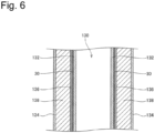
- Fig. 6 is a schematic enlarged view of the region 5R in Fig. 3 , and a cross-section view of the heater 30 and parts around it.
- the heater 30 is the above-explained film heater, and is wound around the periphery of the inner-side cylindrical member 132 which can accept the smoking article 110. That is, the heater 30 is wound in such a manner that it forms a cylinder shape surrounding the inner-side cylindrical member 132. As a result, the heater 30 surrounds the outer periphery of the smoking article, and can heat the smoking article 110 from the outside thereof.
- a heat-shrinkable tube 136 may be installed on the outer side of the heater 30.
- the heater 30 be installed in the heat-shrinkable tube 136.
- the heat-shrinkable tube 136 is a tube 136 which shrinks in a radius direction when heat is applied, and may be constructed by use of thermoplastic elastomer, for example.
- the heater 30 is pushed to the inner-side cylindrical member 132.
- adhesion between the heater 30 and the inner-side cylindrical member 132 is enhanced, so that heat conductivity from the heater 30 to the smoking article 220 via the inner-side cylindrical member 132 is improved.
- the aerosol generation device 120 may comprise a heat insulating material 138 having a cylindrical shape, on the outer side in the radius direction of the heater 30, preferably, on the outer side of the heat-shrinkable tube 136. It is preferable that the heat insulating material 138 be positioned to surround the outer periphery of the heater 30.
- the heat insulating material 138 may fulfill a role to prevent the temperature of the outer surface of the housing of the aerosol generation device 120 from reaching excessively high temperature, by blocking the heat from the heater 30.
- the heat insulating material 138 may be constructed by using aerogel, such as silica aerogel, carbon aerogel, alumina aerogel, or the like, for example.
- the aerogel used as the heat insulating material 138 may be silica aerogel which has a high heat insulation property and can be manufactured by spending a relatively low cost.
- the heat insulating material 138 may be fiber-type heat insulating material such as glass wool, rock wool, or the like, or may be a foam-type heat insulating material such as urethane foam or phenol foam.
- the heat insulating material 138 may be a vacuum insulating material.
- the insulating material 138 may be installed in a position between the inner-side cylindrical member 132 facing the smoking article 110 and an outer-side cylindrical member 134 on the outer side of the insulating material 138.
- the outer-side cylindrical member 134 may be constructed by using a heat conducting member which comprises aluminum or stainless steel (SUS), for example. It is preferable that the insulating material 138 be installed in a closed space.
- Fig. 7 is a figure schematically showing positional relationship, in an axis-line direction, between the base part 11A in the smoking article 110 and the heater 30 and the inner-side cylindrical member 132 in the aerosol generation device 120, in the flavor inhaler 100.
- the axis-line in the present case means the center axis of the insertion hole 130 in the aerosol generation device 120, and, when the smoking article 110 is inserted in the insertion hole 130, the axis-line and the center axis of the smoking article 110 partially overlap with each other (refer to Fig. 3 , also).
- the length D0 of the heater 30 in the axis-line direction can be set to that shorter than the length L0 of the base part 11A in the axis-line direction in the smoking article 110 (D0 ⁇ L0). Further, the ratio of the length D0 to the length L0 (D0/L0) may be 0.70-0.90, preferably, 0.75-0.85, and, typically, 0.80. Thus, in the case that the length L0 of the base part 11A is 20 mm, the length D0 of the heater 30 may be 14-18 mm, preferably, 15-17 mm, and, typically, 16 mm.
- the upstream end of the base member 11A may protrude toward the upstream side above the upstream end of the heater 30 by the length of D1.
- the upstream side and the downstream side in the present case correspond to the upstream side and the downstream side of the flow of air passing through the inside of the air flow path 160 as a result of suction action by a user (refer to Fig. 3 , also).
- the part, which protrudes from the heater 30, of the base part 11A does not have the heater 30 on the outer side in the radius direction of the base part 11A, so that the temperature in the inside thereof may become somewhat lower, compared with the temperature of the other part of the base part 11A.
- the ratio of the protruded length D1 to the whole length L0 of the base part 11A may be 0.25-0.40, preferably, 0.30-0.35, and typically, 0.325.
- the protruded length D1 may be 5-8 mm, preferably, 6-7 mm, and, typically, 6.5 mm.
- the downstream end of the heater 30 may protrude toward the downstream side below the downstream end of the base part 11A by the length of D2.
- the ratio of the protruded length D2 of the heater 30 to the length L0 of the base part 11A may be 0.075-0.175, preferably, 0.1-0.15, and typically, 0.125.
- the protruded length D2 of the heater 30 may be 1.5-3.5 mm, preferably, 2-3 mm, and, typically, 2.5 mm.
- the position of the upstream end of the inner-side cylindrical member 132 and the position of the upstream end of the base part 11A in the axis-line direction may roughly coincide with each other.
- the downstream end of the inner-side cylindrical member 132 may protrude toward the downstream side below the downstream end of the base part 11A by the length of D3.
- the ratio of the protruded length D3 of the inner-side cylindrical member 132 to the protruded length D2 of the heater 30 may be 2.6-3.4, preferably, 2.8-3.2, and, more preferably, 3.0.
- the protruded length D3 of the inner-side cylindrical member 132 may be 6.5-8.5 mm, preferably, 7.0-8.0 mm, and, typically, 7.5 mm.
- the control unit 20 may comprise a control board, a CPU, a memory, and so on.
- the CPU and the memory are components for constructing the control part 22 which controls the heater 30 for heating an aerosol source.
- the control unit 20 has a notification part 40 for reporting a variety of information to a user.
- the notification part 40 may be a light emitting element such as an LED or a vibrating element, or a combination thereof.
- the control part 22 when it has detected an activation request issued by a user, starts supply of electric power from the battery 10 to the heater 30.
- the user's activation request is generated, for example, as a result of manipulation of a push button or a slide-type switch by a user, or a suction action by a user.
- the user's activation request is generated as a result of pressing of the push button 150. More specifically, the user's activation request is generated as a result of pressing of the push button 150 during the state that the lid part 140 is being opened.
- the user's activation request may be generated when a suction action by a user is detected.
- a suction action by a user may be detected by a temperature sensor such as that explained above.
- a heating profile is a graph showing time variation of target temperature in controlling of the heater.
- a delivery profile is a graph showing time variation of the quantity of main aerosol components per single suction action, that is delivered to the inside of the mouth of a user when the user has performed the suction action by using the smoking article 110.
- Fig. 8 is a figure showing a heating profile of the heater 30 and a delivery profile of main aerosol components.
- the vertical axis in Fig. 8 represents the temperature of the heater or the quantity of delivery of main aerosol components.
- the horizontal axis in Fig. 8 represents time.
- main aerosol components refers to visible aerosol components which are generated when various aerosol sources included in a smoking article is heated to have temperature above predetermined temperature.
- the aerosol sources included in a smoking article are propylene glycol and glycerin.
- the smoking article comprises a flavor source such as tobacco or the like
- an aerosol component originated from the flavor source is included in the main aerosol components.
- an aerosol component originated from moisture included in the smoking article is not regarded as an object to be included in the main aerosol components.
- the delivery profile of the main aerosol components may be measured by using a method such as that explained below.
- an aerosol generation device with respect to which a delivery profile of main aerosol components should be measured, is prepared.
- suction from a suction opening part of the smoking article by using an automatic smoking device (that is manufactured by Borgwaldt KC Inc., for example), is performed.
- the heater 30 is heated according to a control method defined with respect to the prepared aerosol generation device.
- suction conditions conditions equivalent to HCI conditions (HCI; health Canada Intense) defined by Health Canada are adopted.
- the suction conditions are as follows: the quantity of suction, 27.5 ml per second; suction time, 2 seconds per single action; and the interval between suction actions, 20 seconds.
- the aerosol sucked by the automatic smoking device under the above suction conditions is collected by a Cambridge filter (for example, CM-133 manufactured by Borgwaldt KC Inc.). Specifically, smoke, that has passed through the above Cambridge filter, is collected in 10mL of methanol which has been cooled to -70 degrees Celsius by using a dry ice-isopropanol refrigerant.
- a Cambridge filter for example, CM-133 manufactured by Borgwaldt KC Inc.
- the 10 mL of methanol solution, in which the tobacco smoke has been collected, and an internal standard solution (0.05 mg/mL of pentadecane-d32, 50 ml/L of d-1-ethanol, 2 mL/L of anethole, and 4 mL/L of 1,3-butanediol) are added to the Cambridge filter, and it is shook for 30 minutes, and contained components are extracted.
- an internal standard solution 0.05 mg/mL of pentadecane-d32, 50 ml/L of d-1-ethanol, 2 mL/L of anethole, and 4 mL/L of 1,3-butanediol
- the delivery profile of the main aerosol components comprises an initial period Q1, an intermediate period Q2, and a final period Q3.
- the initial period Q1 is a period during that a gradient with respect to the main aerosol components relative to time gradually increases.
- the initial period Q1 is a period during that the quantity of increase in the quantity of delivery of the main aerosol components per each suction action increases gradually.
- the gradient of the delivery profile of the main aerosol components is an absolute value of a slope of each point on the curve which forms the delivery profile.
- the gradient of the delivery profile of the main aerosol components can be defined by using the following method, for example.
- the delivery profile of the main aerosol components on the time axis is derived discretely.
- the gradient of the delivery profile of the main aerosol components may be defined, with respect to plotted points that are adjacent to each other on the time axis, by a value obtained by dividing a difference in the delivery profile of the main aerosol components by a difference in time between the plotted points.
- the gradient of the delivery profile of the main aerosol components may be derived, for example, by using an approximate curve derived based on discrete plotting.
- an analytic formula of the approximate curve is defined, the gradient of the delivery profile of the main aerosol components can be defined by calculating a differential value of the analytic formula.
- An approximate curve such as that explained above may be derived, for example, by using a polynomial expression or by using a trigonometric function.
- the start point S0 of the delivery profile is defined by the start point of the aerosol suction allowable period (the suction allowable period) (refer to Fig. 9 ). Specifically, the start point S0 of the delivery profile is defined by reporting of a start of the suction allowable period (the timing T2 in Fig. 9 ) that will be explained later.
- the boundary S1 between the initial period Q1 and the intermediate period Q2 may be defined by a point whereat the gradient of the main aerosol components in the initial period Q1 becomes the largest.
- the boundary S1 between the initial period Q1 and the intermediate period Q2 is a point whereat decreasing of the first time in the gradient of the main aerosol components in the whole delivery profile starts.
- the boundary S1 between the initial period Q1 and the intermediate period Q2 may be defined by a point of inflection.
- the final period Q3 is a period during that a gradient with respect to the main aerosol components relative to time gradually decreases.
- the final period Q3 is a period during that the quantity of decrease in the quantity of delivery of the main aerosol components per each suction action decreases gradually.
- the end point S3 of the delivery profile is defined by the end point of the aerosol suction allowable period (the suction allowable period) (refer to Fig. 9 ). Specifically, the end point S3 of the delivery profile is defined by timing when a report of an end of the suction allowable period is provided (the timing T7 in Fig. 9 ).
- the boundary S2 between the intermediate period Q2 and the final period Q3 may be defined by a point whereat the gradient of the main aerosol components in the final period Q3 becomes the largest.
- the boundary S2 between the intermediate period Q2 and the final period Q3 is a point whereat decreasing of the last time in the gradient of the main aerosol components in the whole delivery profile starts.
- the boundary S2 between the intermediate period Q2 and the final period Q3 may be defined by a point of inflection.
- the intermediate period Q2 is a period between the initial period Q1 and the final period Q3.
- the intermediate period Q2 includes one or plural maximum values that are larger than the start point and the end point of the delivery profile. In the delivery profile shown in Fig. 8 , the intermediate period Q2 includes a single maximum value (the largest value).
- the quantity of delivery of aerosol increases in a period from the initial period Q1 to the intermediate period Q2, has the maximum value in the intermediate period Q2, and decreases in a period from the intermediate period Q2 to the final period Q3.
- a user can recognize a specific period, i.e., one of the initial period Q1, the intermediate period Q2, and the final period Q3 of the suction allowable period, that the user is presently in, based on sensation felt when sucking aerosol.
- the gradient with respect to the main aerosol components relating to time gradually increases, so that the delivery profile has a downwardly convex shape.
- the delivery profile has an upwardly convex shape.
- the quantity of delivery of aerosol may drastically change at the time of transition from the initial period Q1 to the intermediate period Q2.
- the gradient with respect to the main aerosol components relating to time gradually decreases, so that the delivery profile has a downwardly convex shape.
- the quantity of delivery of aerosol may drastically change at the time of transition from the intermediate period Q2 to the final period Q3.
- the intermediate period Q2 is longer than each of the initial period Q1 and the final period Q3. More preferably, the intermediate period Q2 is equal to or longer than a sum of the initial period Q1 and the final period Q3.
- the intermediate period Q2 may be 50-60% of the whole period, and each of the initial period Q1 and the final period Q3 may be 20-25% of the whole period. According to the above construction, the period, during that the quantity of delivery of main aerosol components is large, becomes relatively long, so that a user can suck the main aerosol components for a relatively long period.
- the quantity of delivery of the main aerosol components at the end point S3 in the final period Q3 be larger than the quantity of delivery of the main aerosol components at the start point S0. In the above case, it is possible to suppress an excessive decrease in the quantity of delivery of the aerosol in the final period Q3. According to the above construction, decreasing of the quantity of delivery of the main aerosol components to a low level during the suction allowable period can be prevented, and, especially, the quantity of delivery of a high level can be maintained until the end of the final period Q2.
- the largest value of the gradient relating to the main aerosol components in the final period Q3 be smaller than the largest value of the gradient relating to the main aerosol components in the first period Q1.
- the speed of increase of the main aerosol components in the initial period Q1 becomes relatively high, so that the quantity of aerosol delivery can be brought to a high level in a relatively early stage in the suction allowable period.
- the gradient relating to the main aerosol components in the final period Q3 is small, so that the speed of decrease of the main aerosol components in the final period Q3 becomes relatively low.
- drastic decrease in the quantity of aerosol delivery in the final period Q3 can be suppressed.
- the quantity of aerosol delivery of a high level can be maintained for a relatively long period.
- the smallest value of the gradient relating to the main aerosol components in the final period Q3 be smaller than the smallest value of the gradient relating to the main aerosol components in the initial period Q1. Since the smallest value of the gradient relating to the main aerosol components in the final period Q3 is small, the speed of decrease of the main aerosol components in the final period Q3 becomes relatively low. Thus, drastic decrease in the quantity of aerosol delivery in the final period Q3 can be suppressed.
- the intermediate period Q2 may comprise a stable period SP wherein the absolute value of the gradient relating to the main aerosol components is smaller than the smallest value of the gradient relating to the main aerosol components in the initial period Q1 and smaller than the smallest value of the gradient relating to the main aerosol components in the final period Q3. That is, the stable period SP is a period wherein change in the quantity of delivery of main aerosol components per each suction action is relatively small.
- the stable period SP be longer than each of the initial period Q1 and the final period Q3.
- the quantity of delivery of main aerosol components is large, and change in the quantity of delivery is small.
- the stable period SP is longer than each of the initial period Q1 and the final period Q3, the main aerosol components can be supplied stably for a relatively long period in the intermediate period Q2.
- the stable period SP be 50-60% of the intermediate period Q2. According to the above construction, the main aerosol components can be supplied stably for a relatively long period in the intermediate period Q2.
- the control part 22 of the aerosol generation device 120 may be constructed to control the heater 30 to realize the above-explained delivery profile of the main aerosol components.
- the delivery profile of the main aerosol components is dependent, mainly, on the heating profile of the heater 30.
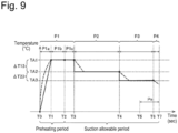
- Fig. 9 shows an example of a heating profile of a heater. It should be reminded that the heating profile shown in Fig. 9 is an example that is appropriate for realizing the above-explained delivery profile of the main aerosol components, and the heating profile is not necessarily limited to the above heating profile.
- the heating profile is a graph showing time variation of target temperature in controlling of the heater 30.
- Temperature control of the heater 30 can be realized by using publicly known feedback control, for example.
- the control part 22 of the aerosol generation device 120 can supply electric power from the battery 22 to the heater 30 in the forms of pulses according to pulse width modulation (PWM) or pulse frequency modulation (PFM).
- PWM pulse width modulation
- PFM pulse frequency modulation
- the control part 22 can perform temperature control of the heater 30 by adjusting the duty ratio of the electric power pulses.
- the control part 22 may measure or estimate temperature of the heater 30, and, based on a difference between the measured or estimated temperature of the heater 30 and a target temperature, or the like, control the electric power supplied to the heater 30, for example, control the above-explained duty ratio.
- the feedback control may be PID control, for example.
- the temperature of the heater can be quantitatively determined, for example, by measuring or estimating an electric resistance value of a heating resistor which is a component of the heater 30. This is because the electric resistance value of the heating resistor changes in response to temperature.
- the electric resistance value of the heating resistor can be estimated, for example, by measuring the quantity of voltage drop in the heating resistor.
- the quantity of voltage drop in the heating resistor can be measured by a voltage sensor which measures a potential difference applied to the heating resistor.
- the temperature of the sensor may be measured by a temperature sensor installed in a position near the heater 30.
- supply of electric power to the heater 30 may be controlled in such a manner that the actual temperature of the heater 30 approaches a target temperature in the heating profile.
- the heating profile includes a part whereat the target temperature rapidly changes, there may be a case that, in a part such as the above part, separation between the actual temperature of the heater 30 and the target temperature becomes large temporarily.
- a broken line In the heating profile illustrated in Fig. 9 , each of parts, whereat separation between the actual temperature of the heater 30 and the target temperature is large, is shown by using a broken line.
- the control part 22 when supply of electric power from the battery 10 to the heater 30 is started in response to reception of an activation request from a user, the control part 22 first controls the temperature of the heater 30 to bring it to a first target temperature TA1 during a first period P1. That is, the control part 22 heats the heater 30 to raise temperature from initial temperature to the first target temperature TA1. In the first period P1, after the temperature of the heater 30 has reached the first target temperature TA1, the control part 22 performs control to maintain the temperature of the heater 30 at the first target temperature TA1.
- the first target temperature TA1 may be 225-240 degrees Celsius, preferably, and 230 degrees Celsius, typically.
- the speed of raising of temperature of the heater 30 can be increased by setting the first target temperature TA1 in the first period P1 to relatively high temperature. By increasing the speed of raising of temperature of the heater 30, the period from a start of supply of electric power to the heater 30 to the time when suction of aerosol becomes possible can be shortened.
- the control part 22 may be constructed to report, to a user, a state that a suction allowable period has started, in a period that is in the first period P1 and during that the temperature of the heater 30 is being maintained at the first target temperature TA1. Reporting of the state that the suction allowable period has started may be performed by controlling the notification part 40, and, for example, may be performed by performing a control process to change the color of light emitted from a light emitting element such as an LED or the like, a control process to change a light emitting pattern, or a control process to drive a vibration element, or a control process comprising a combination of the above control processes.
- reporting of the state that the suction allowable period has started is performed at timing T2. More specifically, reporting of the state that the suction allowable period has started may be performed at either timing T2 when a predetermined period P1b has elapsed since the time when the temperature of the heater 30 has reached the first target temperature, or timing when a predetermined period has elapsed since the time when supply of electric power to the heater 30 has started, that occurs earlier.
- the predetermined period P1b may be 20-26 seconds, preferably, and 23 seconds, typically.
- control part 22 may be constructed to report, in the latter half of the first period P1, the state that the suction allowable period has started.
- the latter half of the first period P1 means a period after the center of the first period P1.
- the control part 22 operates to proceed the period to a second period P2 that will be explained later.
- the predetermined period P1c may be 5-15 seconds, preferably, and 10 seconds, typically. According to the above construction, the probability of occurrence of an event that a user performs a suction action of the first time during the first period P1 becomes high. In the above case, it is possible to bring a user to perform a suction action of the first time, during a period that the heater temperature is maintained at temperature near the first target temperature TA1 that is the highest temperature in the heating profile.
- the first period P1 changes due to the states of heating, ambient temperature, and so on of the heater 30 and the smoking article 110; however, it may typically be that in the range of 35-55 seconds.
- the control part 22 be constructed to be able to change the length of the first period P1, based on the speed of raising of the temperature of the heater 30 in the first period P1.
- the initial temperature rising period P1a in the first period P1 may be constructed to be changeable, based on the speed of raising of the temperature of the heater 30.
- the control part 22 be constructed to change the length of the first period P1 to become shorter, as the period from a start of heating of the heater 30 to the time when the temperature has reached predetermined temperature becomes shorter.
- the first period P1 ends when a predetermined period (P1b+P1c) has elapsed since the time when the temperature of the heater 30 has reached the first target temperature TA1. That is, if the speed of raising of the temperature of the heater 30 is high, the period P1, that is from the time T0 when supply of electric power to the heater 30 is started to the time when the temperature of the heater 30 reaches the first target temperature TA1, becomes short.
- the predetermined period (P1b+P1c) may be 25-41 seconds, preferably, and 33 seconds, typically.
- variable range of the firs period P1 more specifically, the variable range of the period (P1a+P1b) that ends when a start of the suction allowable period is reported, have a predetermined upper limit value.
- the upper limit value of the period (P1a+P1b), that is from a start of supply of electric power T0 to the time of reporting of a start of the suction allowable period T2 is 40-60 seconds, preferably, and 50 seconds, typically. According to the above construction, it is possible to prevent the control part 22 continuing preheating without transition to the second period P2, in the case that the temperature of the heater 30 does not reach the first target temperature TA1.
- the control part 22 controls the temperature of the heater 30 to change it to a second target temperature TA2 that is lower than the first target temperature TA1. That is, the control part 22 controls the heater 30 to lower the temperature of the heater 30 from the first target temperature TA1, and maintain the temperature at the second target temperature TA2.
- the second target temperature TA2 may be that in the range of 190-210 degrees Celsius, preferably, and 200 degrees Celsius, typically.
- the second period P2 may be that in the range of 105-160 seconds, preferably, and 130 seconds, typically. It is preferable that the second period P2 be longer than each of the first period P1 and a third period P3 that will be explained later. Since the second period is a period during that temperature higher than that in the third period P3 is maintained, the second period is a period during that the aerosol is stably supplied. Thus, the period, during that the aerosol can be stably supplied, can be made relatively long.
- the control part 22 may have a first off period, that is from the end of the first period P1 to an early period in the second period P2, for stopping supply of electric power to the heater 30.
- a first off period that is from the end of the first period P1 to an early period in the second period P2, for stopping supply of electric power to the heater 30.
- the control part 22 can continue measurement of temperature of the heater 30 even in the first off period.
- the control par 22 may be constructed to resume supply of electric power to the heater 30 when the temperature of the heater 30 has decreased and reached temperature near the second target temperature TA2.
- the first off period be a time interval during that a general user cannot perform two or more times of suction actions. If a user performs two or more times of suction actions during the off period, the temperature of the heater 30 may be lowered drastically, and may become that much lower than the second target temperature TA2. In the above case, there may be a risk that the quantity of aerosol generated from the smoking article 110 is reduced. If it is supposed that a time interval between usual suction actions by a general user is approximately 20 seconds, it is preferable that the first off period be that in the range of 15-20 seconds, for example.
- the first target temperature TA1 and the second target temperature TA2 may be set in such a manner that lowering of temperature from the first target temperature TA1 to the second target temperature TA2 as a result of natural cooling during the first off period is completed in the above time range.
- the control part 22 may be constructed to measure elapsed time of the first off period, and, when the first off period has reached a predetermined upper limit value, forcibly resume supply of electric power to the heater 30. It is preferable that the upper limit value of the first off period in the above case be 15-20 seconds.
- the control part 22 controls the temperature of the heater 30 to change it to a third target temperature TA3 that is lower than the second target temperature TA2. That is, the control part 22 controls the heater 30 to further lower the temperature of the heater 30 from the second target temperature TA2, and maintain the temperature at the third target temperature TA3.
- the third target temperature TA3 may be that in the range of 175-190 degrees Celsius, preferably, and 185 degrees Celsius, typically.
- the third period P3 may be that in the range of 30-90 seconds, preferably, and 60 seconds, typically.
- a temperature difference ( ⁇ T12) between the first target temperature TA1 and the second target temperature TA2 be larger than a temperature difference ( ⁇ T23) between the second target temperature TA2 and the third target temperature TA3.
- the consumed electric power of the heater 30 in the second period P2 is larger than that in the third period p3, so that electric power consumption through the whole period can be reduced when the temperature difference ( ⁇ T12) at the time of transition from the first period P1 to the second period P2 is set to that larger than the temperature difference ( ⁇ T23) at the time of transition from the second period P2 to the third period P3.
- ⁇ T12/ ⁇ 23 be larger than 1.
- ⁇ T12/ ⁇ 23 have a predetermined upper limit value.
- the upper limit value of ⁇ T12/ ⁇ 23 may be 2.5, for example.
- ⁇ T12/ ⁇ 23 may be 1.0-2.5, preferably, and 2.0, typically.
- the control part 22 may have a second off period, that is from the end of the second period P2 to an early period in the third period P3, for stopping supply of electric power to the heater 30.
- a second off period that is from the end of the second period P2 to an early period in the third period P3, for stopping supply of electric power to the heater 30.
- the control part 22 can continue measurement of temperature of the heater 30 even in the second off period.
- the control par 22 may be constructed to resume supply of electric power to the heater 30 when the temperature of the heater 30 has decreased and reached temperature near the third target temperature TA3.
- the second off period be a time interval during that a general user cannot perform two or more times of suction actions, and that the second off period be that in the range of 15-20 seconds.
- the second target temperature TA2 and the third target temperature TA3 may be set in such a manner that lowering of temperature from the second target temperature TA2 to the third target temperature TA3 as a result of natural cooling during the second off period is completed in the above time range.
- the control part 22 may be constructed to measure elapsed time of the second off period, and, when the second off period has reached a predetermined upper limit value, forcibly resume supply of electric power to the heater 30.
- the temperature difference ( ⁇ T12) between the first target temperature TA1 and the second target temperature TA2 be larger than the temperature difference ( ⁇ T23) between the second target temperature TA2 and the third target temperature TA3; and the above relationship is preferable in view of setting of the first off period and the second off period to make them have values close to each other.
- the speed of lowering of temperature in a high temperature range is faster than that in a low temperature range in the case of natural cooling; thus, for setting the first off period and the second off period as close as possible to each other, it is necessary to set the temperature difference ( ⁇ T12) between the first target temperature TA1 and the second target temperature TA2, that belongs to the high temperature range, to that relatively large.
- the first off period always becomes shorter than the second off period, so that it becomes theoretically impossible to set the two off periods equal to each other.
- the ratio of the difference between the first target temperature TA1 and the second target temperature TA2 to the difference between the second target temperature TA2 and the third target temperature TA3 be less than 2.5.
- the reason that above construction is adopted is to allow stable generation of aerosol during a middle stage in the puff allowable period, by preventing the difference between the first target temperature TA1 and the second target temperature TA2 from becoming excessively large.
- the heater 30 at the third target temperature TA3 without going through the stage of the second target temperature TA2 after the first target temperature TA1.
- the period (the second off period) required to change the temperature from the first target temperature TA1 to the third target temperature TA3 becomes relatively long. Since supply of electric power to the heater 30 is stopped during the period required to reach the third target temperature TA3 from the first target temperature TA1, there may be a risk that the temperature of the heater 30 may become that much lower than the third target temperature, if a user performs plural times of suction actions during the above period.
- the time required for transition from one target temperature to the other target temperature can be shortened.
- duration of an off period during that supply of electric power to the heater 30 is stopped, becomes shorter, so that it becomes possible to prevent excessive lowering of temperature of a smoking article due to plural times of suction actions, and prevent unstable generation of aerosol due thereto.
- the control part 22 stops supply of electric power to the heater 30 at the time when the third period P3 ends.
- the control part 22 reports an end of the suction allowable period at timing T7 when a predetermined period has elapsed since supply of electric power to the heater 30 is stopped (timing T6). That is, even in the time after supply of electric power to the heater 30 is stopped, a user is prompted to perform an aerosol suction action, until a predetermined period has elapsed, to allow the user to taste the aerosol by using remaining heat of the heater 30 and the smoking article 110.
- reporting of the end of the suction allowable period may be performed by the notification part 40, and, for example, may be performed by performing a control process to change the color of light emitted from a light emitting element such as an LED or the like, a control process to change a light emitting pattern, or a control process to drive a vibration element, or a control process comprising a combination of the above control processes.
- a control process to change the color of light emitted from a light emitting element such as an LED or the like
- a control process to change a light emitting pattern or a control process to drive a vibration element, or a control process comprising a combination of the above control processes.
- the heater 30 went through the first period P1, the second period P2, and the third period P3 in the heating profile, heat from the heater 30 has been transferred sufficiently to the inside of the smoking article 110.
- a certain quantity of aerosol can be generated by using remaining heat of the heater 30 and the smoking article 110.
- generation of aerosol becomes unstable in the fourth period P4, so that it is preferable that the fourth period P4 be a time interval during that a user does not perform two or more times of suction actions.
- the fourth period P4 is preferably 5-15 seconds, and, typically 10 seconds.
- control part 22 may report a state that the suction allowable period is drawing to an end, at timing T5 that is earlier, by a predetermined period Pe, than timing T7 when the end of the suction allowable period is reported.
- Reporting such as that explained above may be performed, for example, 20-40 seconds before the end of the suction allowable period.
- Reporting such as that explained above may be performed by the notification part 40, and, for example, may be performed by performing a control process to change the color of light emitted from a light emitting element such as an LED or the like, a control process to change a light emitting pattern, or a control process to drive a vibration element, or a control process comprising a combination of the above control processes.
- the control part 22 stops supply of electric power to the heater 30 at the time of the end of the third period P3.
- the control part 22 may stop supply of electric power to the heater 30, even in the second period P2 or the third period P3 in the case that the number of times of suction actions by a user exceeds a predetermined number of times.
- a puff action by a user may be detected by the above-explained temperature sensor, for example.
- the delivery profile of the main aerosol components may mainly be dependent on the heating profile of the heater 30.
- the delivery profile of the main aerosol components may basically be a profile corresponding to a temperature profile of the inside of the smoking article 110.
- the temperature profile of the inside of the smoking article 110 follows the hating profile of the heater 30, so that it generally tends to have a shape that is time-delayed relative to the heating profile.
- the first target temperature TA1 in the first period P1 to the highest temperature throughout the heating profile, it becomes easier to form an ascending curve having a steep gradient in the initial period Q1 in the delivery profile of the main aerosol components.
- the temperature of the heater 30 at the second target temperature TA2 during the most part of the second period P2 that follows the first period P1, it becomes easier to form the stable period SP, during that change per suction action is small, in the intermediate period Q2 in the delivery profile of the main aerosol components.
- the temperature of the heater 30 controls it to the third target temperature TA3 that is lower than the second target temperature TA2 during the third period P3 that follows the second period P2, it becomes easier to form a descending curve in the final period Q3 in the delivery profile of the main aerosol components.
- the temperature difference T23 between the second target temperature TA2 and the third target temperature TA3 small, it becomes easier to form a descending curve having a more gentle gradient in the final period Q3 in the delivery profile of the main aerosol components.
- the delivery profile of the main aerosol components is mainly dependent on the heating profile of the heater 30.
- the delivery profile of the main aerosol components may change according to factors such as the shape of the heater 30, presence/absence and the shape of the heat insulating material 138, the size of the smoking article 110, the degree of contact between the heater 30 and the smoking article 110, the position of the heating part of the heater 30 relative to the smoking article 110, and so on.
- the heating profile of the heater 30 and the above factors may be combined appropriately.
- the heater 30 has a cylindrical shape surrounding an outer periphery of a column-shape smoking article, it is hard for the heat transferred to the smoking article 110 to dissipate to the outside, so that it becomes easier for the delivery profile of the main aerosol components to follow the heating profile of the heater 30.
- the cylindrical heat insulating material 138 is positioned on the outer side in a radius direction of the heater 30, it is hard for the heat transferred to the smoking article 110 to dissipate to the outside, so that it becomes easier for the delivery profile of the main aerosol components to follow the heating profile of the heater 30.
- the speed of increase of the delivery profile in the initial period Q1 becomes relatively high, so that the overall ascending curve of the delivery profile in the initial period Q1 may have more steep gradients.
- the speed of decrease of the delivery profile in the final period Q3 becomes relatively low, so that the overall descending curve of the delivery profile in the final period Q3 may have more gentle gradients.
- the size of the smoking article 110 more specifically, the diameter of the smoking article 110
- transfer of the heat from the outer side of the smoking article 110 to the inner side of the smoking article 110 becomes easier.
- the diameter of the smoking article 110 is made smaller, it becomes easier for the delivery profile of the main aerosol components to follow the heating profile of the heater 30.
- the degree of contact between the heater 30 and the smoking article 110 is made high when they are used, it becomes easier for the heat from the heater 30 to be transferred to the smoking article 110. That is, if the space between the smoking article 110 and the insertion hole 130 is set smaller in the state that the smoking article 110 is being inserted in the insertion hole 130, it becomes easier for the delivery profile of the main aerosol components to follow the heating profile of the heater 30.
- the delivery profile of the main aerosol components may be dependent on positional relationship between the smoking article 110 and the heater 30.
- the heater 30 be positioned in such a manner that it extends, in the smoking article 110, from the base part 11A which comprises the aerosol source to the paper tube part 114 which does not comprise the aerosol source. According to the above construction, it becomes easier for the heat from the heater 30 to be transferred sufficiently to the end surface on the downstream side and the place near thereof of the base material 11A, so that it becomes easier for the delivery profile of the main aerosol components to follow the heating profile of the heater 30.
- the inner-side cylindrical member 132 which has an inner peripheral surface which comes in contact with the smoking article 110 and an outer peripheral surface which comes in contact with the heater 3, be positioned in such a manner that it extends from the base part 11A which comprises the aerosol source to the paper tube part 114 which does not comprise the aerosol source.
- the downstream end of the inner-side cylindrical member 132 protrude toward the downstream side below the downstream end of the heater 30.
- the heating part 31 of the heater 30 is a part which is heated actively.
- the heating part 31 of the heater 30 refers to the heating resistor.
- the delivery profile of the main aerosol components may be caused by components constructing the smoking article 110. More specifically, the quantity of moisture in the smoking article 110 may have influence on the speed of increase in the initial period Q1 in the delivery profile of the main aerosol components. For example, in the case that the quantity of moisture in the smoking article 110 is relatively large, the heat from the heater 30 may be used for vaporizing the moisture instead of heating the aerosol source, and the above matter may become a factor to lower the speed of increase in the delivery profile of the main aerosol components. As a result, the part of the delivery profile corresponding to the initial period Q1, as a whole, may have more gentle gradients. As explained above, the aerosol originated from the moisture in the smoking article 110 does not include the main aerosol components, usually.
- the above-explained desired delivery profile of the main aerosol components may be realized.
- a control flow for realizing the heating profile and/or the delivery profile of the main aerosol components, that have been explained above, can be performed by the control part 22. That is, the present invention may include a program for making the flavor inhaler 100 and/or the aerosol generation device 120 perform the above-explained method, and a storage medium in which the program is stored.
- a storage medium such as that explained above may be a non-transient storage medium.
Landscapes
- Cigarettes, Filters, And Manufacturing Of Filters (AREA)
- Manufacture Of Tobacco Products (AREA)
Claims (16)
- Dispositif (120) de génération d'aérosol comprenant :un dispositif de chauffage (30) configuré pour chauffer une périphérie externe d'un article à fumer (110) comprenant une source d'aérosol, etune partie de commande (22) configurée pour commander le dispositif de chauffage (30) ;dans lequel la partie de commande (22) est configurée pour commander le dispositif de chauffage (30) d'une manière telle qu'un profil de distribution d'aérosol dans une période admissible d'aspiration prédéterminée comprend une ou plusieurs valeurs maximales dans une période entre un point de début (T2) et un point de fin (T7) dans la période admissible d'aspiration,dans lequel l'article à fumer (110) comprend une région (11A) d'existence d'aérosol incluant la source d'aérosol, et une région (11B) de non-existence d'aérosol positionnée en aval de la région (11A) d'existence d'aérosol dans la direction d'écoulement d'aérosol généré ;caractérisé en ce que, lorsque l'article à fumer (110) est inséré dans le dispositif (120) de génération d'aérosol, une partie de chauffage du dispositif de chauffage (30) est agencée pour s'étendre de la région (11A) d'existence d'aérosol de l'article à fumer (110) à la région (11B) de non-existence d'aérosol de l'article à fumer (110).
- Dispositif (120) de génération d'aérosol selon la revendication 1, dans lequel la région (11B) de non-existence d'aérosol de l'article à fumer (110) comprend une partie tube de papier (114) et une partie filtre (115).
- Dispositif (120) de génération d'aérosol selon la revendication 2, dans lequel la partie tube de papier (114) et la partie filtre (115) sont adjacentes l'une à l'autre.
- Dispositif (120) de génération d'aérosol selon l'une quelconque des revendications 2 ou 3, dans lequel la partie de chauffage du dispositif de chauffage (30) est agencée pour s'étendre de la région (11A) d'existence d'aérosol de l'article à fumer (110) à la partie tube de papier (114) de la région (11B) de non-existence d'aérosol.
- Dispositif (120) de génération d'aérosol selon la revendication 1 ou 2, dans lequelle dispositif de chauffage (30) est configuré pour être en contact thermique avec la périphérie externe de l'article à fumer (110) pour chauffer la périphérie externe de l'article à fumer (110), etest positionné pour chauffer l'article à fumer (110) de la région d'existence d'aérosol de l'article à fumer à la région de non-existence d'aérosol de l'article à fumer.
- Dispositif (120) de génération d'aérosol selon la revendication 1 ou 2, dans lequelle dispositif de chauffage (30) est un film chauffant enroulé autour de la périphérie externe de l'article à fumer (110) pour chauffer la périphérie externe de l'article à fumer (110), etest positionné pour chauffer l'article à fumer (110) de la région d'existence d'aérosol de l'article à fumer à la région de non-existence d'aérosol de l'article à fumer.
- Dispositif (120) de génération d'aérosol selon la revendication 5 ou 6, comprenant en outre un organe cylindrique (132) de cycle interne configuré pour accepter l'article à fumer (110).
- Dispositif (120) de génération d'aérosol selon l'une quelconque des revendications 1 à 7, comprenant en outre un matériau d'isolation thermique (138) positionné autour de la partie de chauffage du dispositif de chauffage (30).
- Dispositif (120) de génération d'aérosol selon la revendication 8, dans lequel le matériau d'isolation thermique (138) est construit en utilisant un aérogel.
- Dispositif (120) de génération d'aérosol selon les revendications 8 ou 9, dans lequel le matériau d'isolation thermique (138) est un matériau d'isolation thermique de type fibre, un matériau d'isolation thermique de type mousse, ou un matériau d'isolation sous vide.
- Dispositif (120) de génération d'aérosol selon l'une quelconque des revendications 1 à 10, dans lequel la partie de chauffage du dispositif de chauffage (30) présente une forme cylindrique entourant la périphérie externe de l'article à fumer (110) qui présente une forme de colonne.
- Dispositif (120) de génération d'aérosol selon l'une quelconque des revendications 1 à 11, dans lequel la partie de chauffage est un élément de chauffage par résistance.
- Dispositif (120) de génération d'aérosol selon l'une quelconque des revendications 1 à 12, dans lequel la partie de chauffage du dispositif de chauffage (30) fait saillie vers le côté en aval sous une extrémité en aval de la région (11A) d'existence d'aérosol d'une longueur en saillie (D2) de 1,5 à 3,5 mm.
- Dispositif (120) de génération d'aérosol selon la revendication 13, dans lequel un rapport de la longueur en saillie (D2) de la partie de chauffage du dispositif de chauffage (30) à une longueur (L0) de la région (11A) d'existence d'aérosol de l'article à fumer (120) est de 0,075 à 0,175.
- Procédé de chauffage d'un article à fumer (110) comprenant une source d'aérosol par utilisation d'un dispositif (120) de génération d'aérosol, le dispositif (120) de génération d'aérosol comprenantun dispositif de chauffage (30) configuré pour chauffer une périphérie externe de l'article à fumer (120) etune partie de commande (22) configurée pour commander le dispositif de chauffage (30),l'article à fumer comprenantune région (11A) d'existence d'aérosol incluant la source d'aérosol etune région (11B) de non-existence d'aérosol positionnée en aval de la région (11A) d'existence d'aérosol dans la direction d'écoulement d'aérosol généré,le procédé comprenant :l'agencement, lorsque l'article à fumer (110) est inséré dans le dispositif (120) de génération d'aérosol, d'une partie de chauffage du dispositif de chauffage (30) pour qu'elle s'étende de la région (11A) d'existence d'aérosol de l'article à fumer (110) à la région (11B) de non-existence d'aérosol de l'article à fumer (110),le chauffage simultané de la région (11A) d'existence d'aérosol et d'au moins une portion de la région (11B) de non-existence d'aérosol dans le côté région d'existence d'aérosol, etla commande du dispositif de chauffage (30) d'une manière telle qu'un profil de distribution d'aérosol dans une période admissible d'aspiration prédéterminée comprend une ou plusieurs valeurs maximales dans une période entre un point de début (T2) et un point de fin (T7) dans la période admissible d'aspiration.
- Système (100) de génération aérosol comprenant :un article à fumer (110) comprenant une source d'aérosol, etun dispositif (120) de génération d'aérosol selon l'une quelconque des revendications 1 à 14.
Priority Applications (4)
| Application Number | Priority Date | Filing Date | Title |
|---|---|---|---|
| EP23161447.0A EP4212039B1 (fr) | 2018-10-26 | 2018-10-26 | Dispositif de génération d'aérosol, procédé de chauffage d'un article à fumer et système de génération d'aérosol |
| HUE23161447A HUE072072T2 (hu) | 2018-10-26 | 2018-10-26 | Szabályozó egység, aeroszolképzõ eszköz, eljárás és program hevítõegység szabályzására, valamint dohánytermék |
| PL23161447.0T PL4212039T3 (pl) | 2018-10-26 | 2018-10-26 | Urządzenie wytwarzające aerozol, sposób podgrzewania wyrobu do palenia oraz system wytwarzania aerozolu |
| ES23161447T ES3034769T3 (en) | 2018-03-06 | 2018-10-26 | Aerosol generation device, method for heating a smoking article, and aerosol generation system |
Applications Claiming Priority (3)
| Application Number | Priority Date | Filing Date | Title |
|---|---|---|---|
| EP23161447.0A EP4212039B1 (fr) | 2018-10-26 | 2018-10-26 | Dispositif de génération d'aérosol, procédé de chauffage d'un article à fumer et système de génération d'aérosol |
| EP18937682.5A EP3871527B1 (fr) | 2018-10-26 | 2018-10-26 | Unité de commande, dispositif de génération d'aérosol, procédé et programme de commande d'appareil de chauffage |
| PCT/JP2018/039918 WO2020084775A1 (fr) | 2018-10-26 | 2018-10-26 | Unité de commande, dispositif de génération d'aérosol, procédé et programme de commande d'appareil de chauffage et article pour fumeur |
Related Parent Applications (2)
| Application Number | Title | Priority Date | Filing Date |
|---|---|---|---|
| EP18937682.5A Division EP3871527B1 (fr) | 2018-10-26 | 2018-10-26 | Unité de commande, dispositif de génération d'aérosol, procédé et programme de commande d'appareil de chauffage |
| EP18937682.5A Division-Into EP3871527B1 (fr) | 2018-10-26 | 2018-10-26 | Unité de commande, dispositif de génération d'aérosol, procédé et programme de commande d'appareil de chauffage |
Publications (3)
| Publication Number | Publication Date |
|---|---|
| EP4212039A1 EP4212039A1 (fr) | 2023-07-19 |
| EP4212039C0 EP4212039C0 (fr) | 2025-05-07 |
| EP4212039B1 true EP4212039B1 (fr) | 2025-05-07 |
Family
ID=70330670
Family Applications (3)
| Application Number | Title | Priority Date | Filing Date |
|---|---|---|---|
| EP25211403.8A Pending EP4659606A3 (fr) | 2018-10-26 | 2018-10-26 | Unité de commande, dispositif de génération d'aérosol, procédé et programme de commande de dispositif de chauffage |
| EP18937682.5A Active EP3871527B1 (fr) | 2018-10-26 | 2018-10-26 | Unité de commande, dispositif de génération d'aérosol, procédé et programme de commande d'appareil de chauffage |
| EP23161447.0A Active EP4212039B1 (fr) | 2018-03-06 | 2018-10-26 | Dispositif de génération d'aérosol, procédé de chauffage d'un article à fumer et système de génération d'aérosol |
Family Applications Before (2)
| Application Number | Title | Priority Date | Filing Date |
|---|---|---|---|
| EP25211403.8A Pending EP4659606A3 (fr) | 2018-10-26 | 2018-10-26 | Unité de commande, dispositif de génération d'aérosol, procédé et programme de commande de dispositif de chauffage |
| EP18937682.5A Active EP3871527B1 (fr) | 2018-10-26 | 2018-10-26 | Unité de commande, dispositif de génération d'aérosol, procédé et programme de commande d'appareil de chauffage |
Country Status (8)
| Country | Link |
|---|---|
| EP (3) | EP4659606A3 (fr) |
| JP (3) | JPWO2020084775A1 (fr) |
| CN (1) | CN112969376A (fr) |
| ES (1) | ES3063982T3 (fr) |
| HU (1) | HUE072072T2 (fr) |
| PL (2) | PL4212039T3 (fr) |
| TW (1) | TW202015563A (fr) |
| WO (1) | WO2020084775A1 (fr) |
Families Citing this family (25)
| Publication number | Priority date | Publication date | Assignee | Title |
|---|---|---|---|---|
| US20250386873A1 (en) * | 2002-09-05 | 2025-12-25 | Kt&G Corporation | Aerosol generating device and operating method thereof |
| WO2022009362A1 (fr) * | 2020-07-09 | 2022-01-13 | 日本たばこ産業株式会社 | Unité de corps principal pour dispositif de génération d'aérosol, dispositif de génération d'aérosol et inhalateur de type sans combustion |
| EP4179894A4 (fr) * | 2020-07-09 | 2024-03-27 | Japan Tobacco Inc. | Unité de corps principal pour dispositif de génération d'aérosol, dispositif de génération d'aérosol, et appareil pour inhalation de type sans combustion |
| CN213587421U (zh) * | 2020-08-13 | 2021-07-02 | 深圳市合元科技有限公司 | 气雾生成装置 |
| KR102522678B1 (ko) * | 2020-12-31 | 2023-04-17 | 주식회사 케이티앤지 | 에어로졸 생성 장치 |
| US11789476B2 (en) | 2021-01-18 | 2023-10-17 | Altria Client Services Llc | Heat-not-burn (HNB) aerosol-generating devices including intra-draw heater control, and methods of controlling a heater |
| US12520880B2 (en) | 2021-01-18 | 2026-01-13 | Altria Client Services Llc | Heat-not-burn (HNB) aerosol-generating devices including energy based heater control, and methods of controlling a heater |
| KR102621761B1 (ko) | 2021-04-01 | 2024-01-05 | 주식회사 케이티앤지 | 에어로졸 생성 물품이 과습 상태인지 여부를 판단하는 에어로졸 생성 장치 |
| WO2022230009A1 (fr) | 2021-04-26 | 2022-11-03 | 日本たばこ産業株式会社 | Inhalateur d'arôme |
| WO2022230433A1 (fr) * | 2021-04-28 | 2022-11-03 | 日本たばこ産業株式会社 | Unité d'alimentation pour inhalateur |
| KR20240006596A (ko) * | 2021-05-10 | 2024-01-15 | 제이티 인터내셔널 소시에떼 아노님 | 2개의 발열체를 포함하는 에어로졸 발생 장치 |
| JP7634097B2 (ja) * | 2021-07-14 | 2025-02-20 | 日本たばこ産業株式会社 | 香味吸引器及びヒータの製造方法 |
| EP4329427A4 (fr) * | 2021-07-21 | 2025-01-22 | Japan Tobacco Inc. | Système de génération d'aérosol |
| WO2023058220A1 (fr) | 2021-10-08 | 2023-04-13 | 日本たばこ産業株式会社 | Inhalateur d'arôme |
| WO2023058218A1 (fr) | 2021-10-08 | 2023-04-13 | 日本たばこ産業株式会社 | Inhalateur d'arôme et procédé de fabrication d'inhalateur d'arôme |
| US12550942B2 (en) | 2022-09-19 | 2026-02-17 | Altria Client Services Llc | Session control system |
| KR102871035B1 (ko) * | 2022-10-14 | 2025-10-15 | 주식회사 이노아이티 | 히팅 부스트 에어로졸 발생 장치 |
| EP4613137A1 (fr) | 2022-10-31 | 2025-09-10 | Japan Tobacco Inc. | Système de gestion d'informations relatives au tabagisme |
| KR20250114938A (ko) * | 2022-12-16 | 2025-07-29 | 니뽄 다바코 산교 가부시키가이샤 | 향미 흡인기 및 향미 흡인기 제조 방법 |
| EP4635321A1 (fr) * | 2022-12-16 | 2025-10-22 | Japan Tobacco Inc. | Inhalateur d'arôme |
| KR20260007246A (ko) | 2023-06-22 | 2026-01-13 | 니뽄 다바코 산교 가부시키가이샤 | 향미 생성체 제조 방법 및 향미 생성체 |
| JPWO2024261961A1 (fr) | 2023-06-22 | 2024-12-26 | ||
| KR20260007260A (ko) | 2023-06-22 | 2026-01-13 | 니뽄 다바코 산교 가부시키가이샤 | 향미 생성체 제조 방법, 및 향미 생성체 |
| KR20260038294A (ko) | 2023-09-07 | 2026-03-18 | 니뽄 다바코 산교 가부시키가이샤 | 향미 생성 물품 |
| KR20260047248A (ko) | 2023-09-07 | 2026-04-07 | 니뽄 다바코 산교 가부시키가이샤 | 향미 발생 물품 |
Citations (7)
| Publication number | Priority date | Publication date | Assignee | Title |
|---|---|---|---|---|
| US6615840B1 (en) | 2002-02-15 | 2003-09-09 | Philip Morris Incorporated | Electrical smoking system and method |
| WO2013060781A1 (fr) | 2011-10-27 | 2013-05-02 | Philip Morris Products S.A. | Système de production d'aérosol avec une production améliorée d'aérosol |
| WO2014020953A1 (fr) | 2012-08-03 | 2014-02-06 | Shimizu Kazuhiko | Gabarit à fumer sans fumée |
| WO2014102091A1 (fr) | 2012-12-28 | 2014-07-03 | Philip Morris Products S.A. | Dispositif de génération d'aérosol chauffé et procédé permettant de générer un aérosol aux propriétés homogènes |
| EP3039974A1 (fr) | 2013-09-30 | 2016-07-06 | Japan Tobacco, Inc. | Inhalateur d'arôme sans combustion |
| WO2017036950A2 (fr) | 2015-08-31 | 2017-03-09 | British American Tobacco (Investments) Limited | Appareil pour chauffer une substance à fumer |
| WO2017194769A1 (fr) | 2016-05-13 | 2017-11-16 | British American Tobacco (Investments) Limited | Appareil et procédé de chauffage d'une matière à fumer |
Family Cites Families (11)
| Publication number | Priority date | Publication date | Assignee | Title |
|---|---|---|---|---|
| CA2829043C (fr) * | 2011-04-22 | 2019-09-03 | Chong Corporation | Systeme d'administration de medicament |
| EP3892125A3 (fr) * | 2011-09-06 | 2022-01-05 | Nicoventures Trading Limited | Chauffage de substance fumable |
| TWI546023B (zh) * | 2011-10-27 | 2016-08-21 | 菲利浦莫里斯製品股份有限公司 | 具有氣溶膠生產控制之電操作氣溶膠產生系統 |
| GB2519101A (en) * | 2013-10-09 | 2015-04-15 | Nicoventures Holdings Ltd | Electronic vapour provision system |
| NZ718007A (en) * | 2013-10-29 | 2017-06-30 | British American Tobacco Investments Ltd | Apparatus for heating smokable material |
| US11696604B2 (en) * | 2014-03-13 | 2023-07-11 | Rai Strategic Holdings, Inc. | Aerosol delivery device and related method and computer program product for controlling an aerosol delivery device based on input characteristics |
| CN111772243B (zh) * | 2015-02-06 | 2023-08-04 | 菲利普莫里斯生产公司 | 改进的用于气溶胶生成装置的提取器 |
| AR109120A1 (es) | 2016-07-26 | 2018-10-31 | British American Tobacco Investments Ltd | Aparato para calentar material fumable |
| CA3031874C (fr) * | 2016-07-27 | 2022-01-04 | Japan Tobacco Inc. | Inhalateur d'arome |
| UA126477C2 (uk) * | 2017-03-30 | 2022-10-12 | Кт & Г Корпорейшон | Пристрій для генерування аерозолю та люлька, здатна його приймати |
| CN110494051B (zh) * | 2017-04-11 | 2022-09-23 | 韩国烟草人参公社 | 气溶胶生成装置 |
-
2018
- 2018-10-26 EP EP25211403.8A patent/EP4659606A3/fr active Pending
- 2018-10-26 WO PCT/JP2018/039918 patent/WO2020084775A1/fr not_active Ceased
- 2018-10-26 CN CN201880099054.4A patent/CN112969376A/zh active Pending
- 2018-10-26 PL PL23161447.0T patent/PL4212039T3/pl unknown
- 2018-10-26 HU HUE23161447A patent/HUE072072T2/hu unknown
- 2018-10-26 PL PL18937682.5T patent/PL3871527T3/pl unknown
- 2018-10-26 ES ES18937682T patent/ES3063982T3/es active Active
- 2018-10-26 JP JP2020552484A patent/JPWO2020084775A1/ja active Pending
- 2018-10-26 EP EP18937682.5A patent/EP3871527B1/fr active Active
- 2018-10-26 EP EP23161447.0A patent/EP4212039B1/fr active Active
- 2018-11-15 TW TW107140580A patent/TW202015563A/zh unknown
-
2023
- 2023-05-24 JP JP2023085110A patent/JP7623422B2/ja active Active
-
2025
- 2025-01-16 JP JP2025005974A patent/JP2025061372A/ja active Pending
Patent Citations (7)
| Publication number | Priority date | Publication date | Assignee | Title |
|---|---|---|---|---|
| US6615840B1 (en) | 2002-02-15 | 2003-09-09 | Philip Morris Incorporated | Electrical smoking system and method |
| WO2013060781A1 (fr) | 2011-10-27 | 2013-05-02 | Philip Morris Products S.A. | Système de production d'aérosol avec une production améliorée d'aérosol |
| WO2014020953A1 (fr) | 2012-08-03 | 2014-02-06 | Shimizu Kazuhiko | Gabarit à fumer sans fumée |
| WO2014102091A1 (fr) | 2012-12-28 | 2014-07-03 | Philip Morris Products S.A. | Dispositif de génération d'aérosol chauffé et procédé permettant de générer un aérosol aux propriétés homogènes |
| EP3039974A1 (fr) | 2013-09-30 | 2016-07-06 | Japan Tobacco, Inc. | Inhalateur d'arôme sans combustion |
| WO2017036950A2 (fr) | 2015-08-31 | 2017-03-09 | British American Tobacco (Investments) Limited | Appareil pour chauffer une substance à fumer |
| WO2017194769A1 (fr) | 2016-05-13 | 2017-11-16 | British American Tobacco (Investments) Limited | Appareil et procédé de chauffage d'une matière à fumer |
Also Published As
| Publication number | Publication date |
|---|---|
| PL4212039T3 (pl) | 2025-09-01 |
| EP3871527A4 (fr) | 2022-06-22 |
| EP4212039C0 (fr) | 2025-05-07 |
| ES3063982T3 (en) | 2026-04-21 |
| TW202015563A (zh) | 2020-05-01 |
| JP2025061372A (ja) | 2025-04-10 |
| EP4659606A3 (fr) | 2026-03-04 |
| EP3871527A1 (fr) | 2021-09-01 |
| CN112969376A (zh) | 2021-06-15 |
| JP7623422B2 (ja) | 2025-01-28 |
| JP2023103468A (ja) | 2023-07-26 |
| EP3871527C0 (fr) | 2025-12-17 |
| PL3871527T3 (pl) | 2026-03-23 |
| HUE072072T2 (hu) | 2025-10-28 |
| EP4212039A1 (fr) | 2023-07-19 |
| WO2020084775A1 (fr) | 2020-04-30 |
| EP4659606A2 (fr) | 2025-12-10 |
| EP3871527B1 (fr) | 2025-12-17 |
| JPWO2020084775A1 (ja) | 2021-10-14 |
Similar Documents
| Publication | Publication Date | Title |
|---|---|---|
| EP4212039B1 (fr) | Dispositif de génération d'aérosol, procédé de chauffage d'un article à fumer et système de génération d'aérosol | |
| EP3871530B1 (fr) | Unité de commande, dispositif de génération d'aérosol, et procédé et programme de commande de dispositif de chauffage | |
| EP3871531A1 (fr) | Unité de commande, dispositif de génération d'aérosol, procédé et programme de commande de dispositif de chauffage, et article à fumer | |
| JP7772882B2 (ja) | 固体エアロゾル発生源を実装する加熱装置を含む電子喫煙物品、ならびに関連付けられる装置及び方法 | |
| KR102918246B1 (ko) | 에어로졸 생성 디바이스 및 에어로졸 생성 디바이스를 위한 가열 챔버 | |
| KR102894626B1 (ko) | 에어로졸 생성 디바이스 및 에어로졸 생성 디바이스를 위한 가열 챔버 | |
| KR102881210B1 (ko) | 에어로졸 생성 디바이스 및 에어로졸 생성 디바이스를 위한 가열 챔버 | |
| TWI824054B (zh) | 霧劑輸送裝置及控制本體 | |
| KR102884879B1 (ko) | 에어로졸 생성 디바이스 및 에어로졸 생성 디바이스를 위한 가열 챔버 | |
| CN111726996B (zh) | 气溶胶生成装置、其控制方法以及计算机可读记录介质 | |
| KR102888604B1 (ko) | 에어로졸 생성 디바이스 및 에어로졸 생성 디바이스를 위한 가열 챔버 | |
| KR102881212B1 (ko) | 에어로졸 생성 디바이스 및 에어로졸 생성 디바이스를 위한 가열 챔버 | |
| KR20210075112A (ko) | 에어로졸 생성 디바이스 및 에어로졸 생성 디바이스를 위한 가열 챔버 | |
| RU2852216C2 (ru) | Устройство генерации аэрозоля, способ нагрева курительного изделия с использованием устройства генерации аэрозоля и система генерации аэрозоля, содержащая курительное изделие, содержащее источник аэрозоля, и устройство генерации аэрозоля | |
| RU2772840C1 (ru) | Блок управления, устройство генерации аэрозоля, способ управления нагревателем, машиночитаемый носитель данных и курительное изделие | |
| JP7190554B2 (ja) | 制御ユニット、エアロゾル生成装置、ヒータを制御する方法及びプログラム、並びに喫煙物品 | |
| RU2772162C1 (ru) | Блок управления, аэрозоль-генерирующее устройство, способ и компьютерно-читаемый носитель данных для управления нагревателем, а также курительное изделие | |
| ES3034769T3 (en) | Aerosol generation device, method for heating a smoking article, and aerosol generation system |
Legal Events
| Date | Code | Title | Description |
|---|---|---|---|
| PUAI | Public reference made under article 153(3) epc to a published international application that has entered the european phase |
Free format text: ORIGINAL CODE: 0009012 |
|
| STAA | Information on the status of an ep patent application or granted ep patent |
Free format text: STATUS: REQUEST FOR EXAMINATION WAS MADE |
|
| 17P | Request for examination filed |
Effective date: 20230313 |
|
| AC | Divisional application: reference to earlier application |
Ref document number: 3871527 Country of ref document: EP Kind code of ref document: P |
|
| AK | Designated contracting states |
Kind code of ref document: A1 Designated state(s): AL AT BE BG CH CY CZ DE DK EE ES FI FR GB GR HR HU IE IS IT LI LT LU LV MC MK MT NL NO PL PT RO RS SE SI SK SM TR |
|
| STAA | Information on the status of an ep patent application or granted ep patent |
Free format text: STATUS: EXAMINATION IS IN PROGRESS |
|
| 17Q | First examination report despatched |
Effective date: 20240416 |
|
| GRAP | Despatch of communication of intention to grant a patent |
Free format text: ORIGINAL CODE: EPIDOSNIGR1 |
|
| STAA | Information on the status of an ep patent application or granted ep patent |
Free format text: STATUS: GRANT OF PATENT IS INTENDED |
|
| RIC1 | Information provided on ipc code assigned before grant |
Ipc: A24F 40/20 20200101ALN20241028BHEP Ipc: A24F 40/57 20200101ALI20241028BHEP Ipc: A24F 40/50 20200101AFI20241028BHEP |
|
| INTG | Intention to grant announced |
Effective date: 20241129 |
|
| GRAS | Grant fee paid |
Free format text: ORIGINAL CODE: EPIDOSNIGR3 |
|
| GRAA | (expected) grant |
Free format text: ORIGINAL CODE: 0009210 |
|
| STAA | Information on the status of an ep patent application or granted ep patent |
Free format text: STATUS: THE PATENT HAS BEEN GRANTED |
|
| AC | Divisional application: reference to earlier application |
Ref document number: 3871527 Country of ref document: EP Kind code of ref document: P |
|
| AK | Designated contracting states |
Kind code of ref document: B1 Designated state(s): AL AT BE BG CH CY CZ DE DK EE ES FI FR GB GR HR HU IE IS IT LI LT LU LV MC MK MT NL NO PL PT RO RS SE SI SK SM TR |
|
| REG | Reference to a national code |
Ref country code: GB Ref legal event code: FG4D |
|
| REG | Reference to a national code |
Ref country code: CH Ref legal event code: EP |
|
| REG | Reference to a national code |
Ref country code: DE Ref legal event code: R096 Ref document number: 602018081867 Country of ref document: DE |
|
| REG | Reference to a national code |
Ref country code: IE Ref legal event code: FG4D |
|
| U01 | Request for unitary effect filed |
Effective date: 20250606 |
|
| U07 | Unitary effect registered |
Designated state(s): AT BE BG DE DK EE FI FR IT LT LU LV MT NL PT RO SE SI Effective date: 20250616 |
|
| REG | Reference to a national code |
Ref country code: ES Ref legal event code: FG2A Ref document number: 3034769 Country of ref document: ES Kind code of ref document: T3 Effective date: 20250822 |
|
| PG25 | Lapsed in a contracting state [announced via postgrant information from national office to epo] |
Ref country code: NO Free format text: LAPSE BECAUSE OF FAILURE TO SUBMIT A TRANSLATION OF THE DESCRIPTION OR TO PAY THE FEE WITHIN THE PRESCRIBED TIME-LIMIT Effective date: 20250807 |
|
| PG25 | Lapsed in a contracting state [announced via postgrant information from national office to epo] |
Ref country code: HR Free format text: LAPSE BECAUSE OF FAILURE TO SUBMIT A TRANSLATION OF THE DESCRIPTION OR TO PAY THE FEE WITHIN THE PRESCRIBED TIME-LIMIT Effective date: 20250507 |
|
| PG25 | Lapsed in a contracting state [announced via postgrant information from national office to epo] |
Ref country code: RS Free format text: LAPSE BECAUSE OF FAILURE TO SUBMIT A TRANSLATION OF THE DESCRIPTION OR TO PAY THE FEE WITHIN THE PRESCRIBED TIME-LIMIT Effective date: 20250807 |
|
| PG25 | Lapsed in a contracting state [announced via postgrant information from national office to epo] |
Ref country code: IS Free format text: LAPSE BECAUSE OF FAILURE TO SUBMIT A TRANSLATION OF THE DESCRIPTION OR TO PAY THE FEE WITHIN THE PRESCRIBED TIME-LIMIT Effective date: 20250907 |
|
| REG | Reference to a national code |
Ref country code: HU Ref legal event code: AG4A Ref document number: E072072 Country of ref document: HU |
|
| REG | Reference to a national code |
Ref country code: GR Ref legal event code: EP Ref document number: 20250401584 Country of ref document: GR Effective date: 20251009 |
|
| REG | Reference to a national code |
Ref country code: CH Ref legal event code: U11 Free format text: ST27 STATUS EVENT CODE: U-0-0-U10-U11 (AS PROVIDED BY THE NATIONAL OFFICE) Effective date: 20251101 |
|
| U20 | Renewal fee for the european patent with unitary effect paid |
Year of fee payment: 8 Effective date: 20251028 |
|
| PGFP | Annual fee paid to national office [announced via postgrant information from national office to epo] |
Ref country code: HU Payment date: 20251103 Year of fee payment: 8 |
|
| PGFP | Annual fee paid to national office [announced via postgrant information from national office to epo] |
Ref country code: GB Payment date: 20251022 Year of fee payment: 8 |
|
| PG25 | Lapsed in a contracting state [announced via postgrant information from national office to epo] |
Ref country code: SM Free format text: LAPSE BECAUSE OF FAILURE TO SUBMIT A TRANSLATION OF THE DESCRIPTION OR TO PAY THE FEE WITHIN THE PRESCRIBED TIME-LIMIT Effective date: 20250507 |
|
| PGFP | Annual fee paid to national office [announced via postgrant information from national office to epo] |
Ref country code: GR Payment date: 20251022 Year of fee payment: 8 |
|
| PGFP | Annual fee paid to national office [announced via postgrant information from national office to epo] |
Ref country code: CH Payment date: 20251101 Year of fee payment: 8 |
|
| PGFP | Annual fee paid to national office [announced via postgrant information from national office to epo] |
Ref country code: CZ Payment date: 20251020 Year of fee payment: 8 |
|
| PGFP | Annual fee paid to national office [announced via postgrant information from national office to epo] |
Ref country code: PL Payment date: 20251020 Year of fee payment: 8 |
|
| PG25 | Lapsed in a contracting state [announced via postgrant information from national office to epo] |
Ref country code: SK Free format text: LAPSE BECAUSE OF FAILURE TO SUBMIT A TRANSLATION OF THE DESCRIPTION OR TO PAY THE FEE WITHIN THE PRESCRIBED TIME-LIMIT Effective date: 20250507 |
|
| PGFP | Annual fee paid to national office [announced via postgrant information from national office to epo] |
Ref country code: ES Payment date: 20251216 Year of fee payment: 8 |
|
| PLBI | Opposition filed |
Free format text: ORIGINAL CODE: 0009260 |
|
| REG | Reference to a national code |
Ref country code: CH Ref legal event code: L10 Free format text: ST27 STATUS EVENT CODE: U-0-0-L10-L00 (AS PROVIDED BY THE NATIONAL OFFICE) Effective date: 20260218 |
|
| U1N | Appointed representative for the unitary patent procedure changed after the registration of the unitary effect |
Representative=s name: KILBURN & STRODE LLP; GB |
|
| PLAX | Notice of opposition and request to file observation + time limit sent |
Free format text: ORIGINAL CODE: EPIDOSNOBS2 |
|
| 26 | Opposition filed |
Opponent name: NICOVENTURES TRADING LIMITED Effective date: 20260205 |