EP4212357A1 - Bandage pneumatique pour véhicule - Google Patents
Bandage pneumatique pour véhicule Download PDFInfo
- Publication number
- EP4212357A1 EP4212357A1 EP22213647.5A EP22213647A EP4212357A1 EP 4212357 A1 EP4212357 A1 EP 4212357A1 EP 22213647 A EP22213647 A EP 22213647A EP 4212357 A1 EP4212357 A1 EP 4212357A1
- Authority
- EP
- European Patent Office
- Prior art keywords
- area
- tire
- pneumatic vehicle
- range
- vehicle tire
- Prior art date
- Legal status (The legal status is an assumption and is not a legal conclusion. Google has not performed a legal analysis and makes no representation as to the accuracy of the status listed.)
- Pending
Links
Images



Classifications
-
- B—PERFORMING OPERATIONS; TRANSPORTING
- B60—VEHICLES IN GENERAL
- B60C—VEHICLE TYRES; TYRE INFLATION; TYRE CHANGING; CONNECTING VALVES TO INFLATABLE ELASTIC BODIES IN GENERAL; DEVICES OR ARRANGEMENTS RELATED TO TYRES
- B60C9/00—Reinforcements or ply arrangement of pneumatic tyres
- B60C9/02—Carcasses
- B60C9/04—Carcasses the reinforcing cords of each carcass ply arranged in a substantially parallel relationship
- B60C9/07—Carcasses the reinforcing cords of each carcass ply arranged in a substantially parallel relationship the cords curve from bead to bead in plural planes, e.g. S-shaped cords
-
- B—PERFORMING OPERATIONS; TRANSPORTING
- B60—VEHICLES IN GENERAL
- B60C—VEHICLE TYRES; TYRE INFLATION; TYRE CHANGING; CONNECTING VALVES TO INFLATABLE ELASTIC BODIES IN GENERAL; DEVICES OR ARRANGEMENTS RELATED TO TYRES
- B60C17/00—Tyres characterised by means enabling restricted operation in damaged or deflated condition; Accessories therefor
- B60C17/0009—Tyres characterised by means enabling restricted operation in damaged or deflated condition; Accessories therefor comprising sidewall rubber inserts, e.g. crescent shaped inserts
- B60C17/0018—Tyres characterised by means enabling restricted operation in damaged or deflated condition; Accessories therefor comprising sidewall rubber inserts, e.g. crescent shaped inserts two or more inserts in each sidewall portion
-
- B—PERFORMING OPERATIONS; TRANSPORTING
- B60—VEHICLES IN GENERAL
- B60C—VEHICLE TYRES; TYRE INFLATION; TYRE CHANGING; CONNECTING VALVES TO INFLATABLE ELASTIC BODIES IN GENERAL; DEVICES OR ARRANGEMENTS RELATED TO TYRES
- B60C13/00—Tyre sidewalls; Protecting, decorating, marking, or the like, thereof
- B60C2013/005—Physical properties of the sidewall rubber
- B60C2013/006—Modulus; Hardness; Loss modulus or "tangens delta"
Definitions
- the invention relates to a pneumatic vehicle tire.
- the circumferential direction can in particular be referred to as a direction of rotation of the pneumatic vehicle tire.
- the direction of rotation is the direction in which the pneumatic vehicle tire can be rotated about the axis of rotation.
- the pneumatic vehicle tires known from the prior art have, in particular, a tire carcass with a first side area, a second side area and a central area arranged in between, the tire carcass having at least one carcass ply with a large number of rubberized reinforcements, each extending through the first side area, the second extending lateral area and the central area of the tire carcass has. At least some of the rubberized reinforcements of the carcass ply enclose an angle in the range of 80° to 90° with respect to the circumferential direction in the first side area and in the second side area and in the central area an angle in the range of 5° to 75°.
- the tire carcasses arranged according to the prior art in pneumatic vehicle tires are in particular formed from one or more carcass layers, each of which comprises a multiplicity of rubberized reinforcements, ie reinforcements embedded in a crosslinked rubber mixture.
- a radial direction of a pneumatic vehicle tire is a direction that is perpendicular to the axis of rotation of the pneumatic vehicle tire.
- a radial direction is parallel to a radius of a pneumatic tire.
- the radius of a pneumatic vehicle tire is the radius of the circle whose shape the pneumatic vehicle tire basically follows in the direction of rotation; the radius is perpendicular to the axis of rotation and perpendicular to the direction of rotation.
- radially further outward means that a first component of the pneumatic vehicle tire, which is radially further outward than a second component of the pneumatic vehicle tire, is further away from the axis of rotation than the second component of the pneumatic vehicle tire.
- radially further inwards means that a first component of the pneumatic vehicle tire, which is radially further inwards than a second component of the pneumatic vehicle tire, is closer to the axis of rotation than the second component of the pneumatic vehicle tire.
- a radially outer element of the pneumatic vehicle tire is therefore radially further outward than a radially inner element of the pneumatic vehicle tire.
- the rubberized reinforcements of the carcass layers essentially run radial.
- the corresponding angle can also be referred to as the cord angle of the reinforcements present in the carcass ply.
- this cord angle is particularly possible for a person skilled in the art in practice to determine the cord angle, ie the relative angle of the reinforcement to the circumferential direction.
- the carcass of the pneumatic vehicle tire according to the invention has three areas: a first side area, a central area and a second side area.
- the central area can expediently be the area of the tire carcass that is arranged in the pneumatic vehicle tire below the tread strip, whereas the first and second side areas form the carcass in the area of the flanks or sides of the pneumatic vehicle tire, for example.
- the central area is radially inward than the tread.
- the pneumatic vehicle tire deviates from a strictly radial construction, in that a largely radial arrangement of the reinforcements, ie with a cord angle of 80° to 90°, is set only in the first and second side area.
- a cord angle is set in the range of 5° to 75°, so that a tire carcass which can be called a partially angled tire carcass is obtained.
- a cord angle of 5° to 75° means that the rubberized reinforcements of the tire carcass enclose an angle of 5° to 75° with the circumferential direction or direction of rotation.
- the object of the invention is therefore to provide a pneumatic vehicle tire that has a stability that goes beyond the fundamentally sufficient mechanical stability and in which the use of material that is required for the construction and manufacture of the pneumatic vehicle tire is optimally designed.
- the object set according to the invention is achieved in that the respective radially inner side wall area has a Shore A hardness of 65 to 85 points and the respective radially outer side wall area has a Shore A hardness of 45 to 70 points, the each radially inner side wall area has a Shore A hardness that is at least 5 points higher than the respective radially outer side wall area.
- the Shore A hardness points are points on the Shore A hardness scale.
- the respective radially inner side wall area has a Shore A hardness of 65 to 85 points and the respective radially outer side wall area has a Shore A hardness of 45 to 70 points, with the respective radially inner side wall area having a has at least 5 points higher Shore A hardness than the respective radially outer side wall area, sufficient mechanical stability secured.
- the mechanical stability is sufficient in particular if the pneumatic vehicle tire is not damaged during regular operation due to mechanical instability.
- the pneumatic vehicle tire is then used in regular operation if it is used, for example, in a pressure range intended for it and at the intended rolling speeds.
- an improved pneumatic vehicle tire is provided in which the use of material required for the construction and manufacture of the pneumatic vehicle tire is optimized.
- the pneumatic vehicle tire is, for example, a car tire or a truck tire or a two-wheeler tire.
- At least some of the rubberized reinforcements of the carcass ply form an angle in the range of 85° to 90°, preferably in the range of 88° to 90°, in relation to the circumferential direction of the pneumatic vehicle tire in the first lateral area and in the second lateral area. a. This angle is the angle of the rubberized reinforcements to the circumferential direction.
- a next preferred embodiment of the present invention includes at least a portion of the rubberized reinforcement of the Carcass ply relative to the circumferential direction of the pneumatic vehicle tire in the central area at an angle in the range from 10° to 70°, preferably in the range from 15° to 55°, particularly preferably in the range from 20° to 35°. This angle is the angle of the rubberized reinforcements to the circumferential direction.
- the tread strip is arranged at least partially, preferably completely, above the central area in the radially outward-pointing direction.
- the quotient of the width of the contact area and the width of the central area, in each case transversely to the circumferential direction of the pneumatic vehicle tire is in the range from 0.7 to 2, preferably in the range from 0.8 to 1.6. more preferably in the range of 0.9 to 1.2 and most preferably in the range of 0.95 to 1.05.
- An extension transverse to the circumferential direction is an extension parallel to the axis of rotation and perpendicular to the circumferential direction.
- the tire carcass comprises two or more carcass plies, wherein in each carcass ply at least some of the rubberized reinforcements, preferably all rubberized reinforcements, are at an angle in the range of in relation to the circumferential direction of the pneumatic vehicle tire in the first lateral area and in the second lateral area 80° to 90° and in the central area an angle in the range from 5° to 75°. This angle is the angle of the rubberized reinforcements to the circumferential direction.
- the tire carcass comprises two carcass plies, with the rubberized reinforcements of the two carcass plies in the central area relative to one another being at an angle in the range from 30° to 90°, preferably in the range from 40° to 80°. more preferably in the range of 50° to 70°, most preferably in the range of 55° to 65°.
- the rubberized reinforcements of the two carcass plies in the central area relative to one another being at an angle in the range from 30° to 90°, preferably in the range from 40° to 80°, particularly preferably in the range of 50° to 70°, very particularly preferably in the range from 55° to 65°, a cross-bonding of the two carcass plies is brought about.
- This cross bond leads to an increase in the mechanical stability of the pneumatic vehicle tire.
- At least one additional layer is arranged in the pneumatic vehicle tire between the tread strip and the tire carcass.
- the further layer can be, for example, a belt of the pneumatic vehicle tire or a cap ply of the pneumatic vehicle tire.
- At least one of the further layers is a belt layer, the further layer preferably comprising rubberized reinforcements, which particularly preferably have an angle in the range from 10° to 70°, more preferably in the range, relative to the circumferential direction of the pneumatic vehicle tire from 15° to 55°, more preferably in the range from 20° to 35°. This angle is the angle of the rubberized reinforcements to the circumferential direction.
- At least one of the further layers is a cap-ply layer, the further layer preferably comprising rubberized reinforcements, which particularly preferably enclose an angle in the range of 0° to 5° relative to the circumferential direction of the pneumatic vehicle tire.
- the respective radially outer side wall area has a rubber coating thickness of 1.5 mm to 5.0 mm and/or the respective radially inner side wall area has a rubber coating thickness of 2.0 mm to 7.0 mm.
- the respective radially inner side wall area is materially bonded to the respective radially outer side wall area in a respective contact area.
- the respective radially inner side wall area forms a butt joint, a lap joint or an inverse lap joint with the respective radially outer side wall area in the respective contact area.
- the respective contact area runs largely parallel or in particular exactly parallel to the axis of rotation in the event of a butt impact.
- the respective contact areas can also be referred to as first contact area and second contact area.
- the first contact area extends in particular from a first point of the first contact area to a second point of the first contact area, the first point being radially further outward than the second point and the first point being axially further outward relative to a tire interior as the second point.
- the second contact area extends in particular from a first point of the second contact area to a second point of the second contact area, the first point being radially further outward than the second point and the first point being axially further outward relative to a tire interior as the second point.
- Radial refers to an extension parallel to a radius of the pneumatic vehicle tire.
- the first contact area extends in particular from a first point of the first contact area to a second point of the first contact area, the first point being radially further outward than the second point and the first point being axially further inward in relation to a tire interior lies as the second point.
- the second contact area extends in particular from a first point of the second contact area to a second point of the second contact area, the first point being radially further outward than the second point and the first point being axially further inward in relation to a tire interior lies as the second point.
- the first point and the second point of the first contact area and the first point and the second point of the second contact area are loci of the first contact area and the second contact area, respectively.
- a further component is arranged in the tire sidewalls, the respective further component being materially bonded to the respective radially outer sidewall area and the respective radially inner sidewall area.
- the respective further component has a higher Shore hardness than the respective radially inner side wall area and the respective radially outer side wall area.
- the respective further component has a Shore A hardness of 75 to 100 points, the further component having a Shore A hardness that is at least 5 points higher than the respective radially inner side wall region and a has a Shore A hardness that is at least 10 points higher than the respective radially outer side wall region.
- the side wall areas and the other components are made in particular from a caoutchouc or a rubber material.
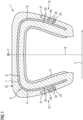
- a pneumatic vehicle tire 1 according to the invention according to one embodiment is shown schematically in a radial sectional view.
- the pneumatic vehicle tire 1 can be rotated about an axis of rotation 2 in a direction of rotation 3 .
- Circumferential direction 3 can also be referred to as circumferential direction 3 .
- the tire sidewalls 12 each have a radially outer sidewall region 21 and a radially inner sidewall region 22, the respective radially inner sidewall region 22 having a Shore A hardness of 65 to 85 points and the respective radially outer Side wall area 21 has a Shore A hardness of 45 to 70 points, with the respective radially inner side wall area 22 having a Shore A hardness that is at least 5 points higher than the respective radially outer side wall area 21.
- the pneumatic vehicle tire 1 is axisymmetric with respect to a tire center plane 13.
- the tire side walls 12 are therefore axisymmetric with respect to the tire center plane 13.
- the center plane 13 of the tire is perpendicular to the axis of rotation 2.
- the geometric center and the physical center of gravity of the pneumatic vehicle tire are in particular in the center plane 13 of the tire.
- the side wall areas 21 each have a rubber coating thickness 23 of 1.5 mm to 5.0 mm.
- the side wall areas 22 each have a rubber coating thickness 23 of 2.0 mm to 7.0 mm.
- the rubber coating thickness 23 can be a maximum spatial extension of the side wall areas 21 and 22.
- the respective radially inner side wall area 22 is cohesively connected to the respective radially outer side wall area 21 in a respective contact area 24 .
- the embodiment illustrated forms the respective radially outer side wall area 21 with the respective radially inner side wall area 22 in the respective contact area 24 from a butt joint.
- the respective contact area 24 preferably runs largely parallel or in particular exactly parallel to the axis of rotation 2 in the event of a butt impact.
- FIG. 2 a region of a pneumatic vehicle tire 1 according to the invention is shown schematically. Shown is the tire carcass 4. According to the illustration in FIG figure 2 part of the rubberized reinforcements 9 of the carcass ply 8 encloses an angle 14 in the range of 80° to 90° with respect to the circumferential direction in the first side area 5 and in the second side area 6 and in the central area 7 an angle 15 in the range of 5° to 75° includes.
- FIG 3 1 is a pneumatic vehicle tire 1 according to the invention according to a further embodiment shown schematically in a radial sectional view, according to the illustration in FIG figure 3 the quotient of the width 16 of the contact area 26 of the pneumatic vehicle tire 1 on a roadway 35 divided by the width 17 of the central region 7, in each case transversely to the circumferential direction or direction of rotation 3, i.e. parallel to the axis of rotation 2, of the pneumatic vehicle tire 1, is in the range of 0.7 to 2, preferably in the range from 0.8 to 1.6, particularly preferably in the range from 0.9 to 1.2, very particularly preferably in the range from 0.95 to 1.05.
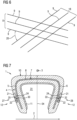
- an area of a pneumatic vehicle tire 1 according to the invention according to a further embodiment is shown schematically in a radial sectional view.
- the tire carcass 4 comprises two carcass plies 8 and 18.
- a pneumatic vehicle tire 1 according to the invention according to a further embodiment is shown schematically in a radial sectional view.
- At least one further layer 19, preferably exactly one further layer 19, is arranged between the tread strip 10 and the tire carcass 4.
- rubberized reinforcements 9 according to the in the figure 4 illustrated embodiment shown schematically.
- the rubberized reinforcements 9 shown are rubberized reinforcements 9 of the carcass plies 8 and 18.
- the rubberized reinforcements 9 of the carcass ply 8 run parallel to one another.
- the rubberized reinforcements 9 of the carcass ply 18 run parallel to one another.
- the rubberized reinforcements 9 of the two carcass plies 8, 18 in the central region 7 completely form an angle 20 relative to one another in the range from 30° to 90°, preferably in the range from 40° to 80°, particularly preferably in the range from 50° to 70° more preferably in the range of 55° to 65°.
- a pneumatic vehicle tire 1 according to the invention according to a further embodiment is shown schematically in a radial sectional view.
- the respective radially outer side wall area 21 forms an overlap joint with the respective radially inner side wall area 22 in the respective contact area 24 .
- the respective contact areas 24 can also be referred to as first contact area 27 and second contact area 28 .
- the first contact area 27 in particular extends from a first point 29 of the first contact area 27 to a second point 30 of the first contact area 27, with the first point 29 being radially further outward than the second point 30 and with the first point 29 relative to a tire interior 31 is axially further outward than the second point 30.
- the second contact area 28 in particular extends from a first point 32 of the second contact area 28 to a second point 33 of the second contact area 28, with the first point 32 being radially further outward than the second point 33 and with the first point 32 relative to a tire interior 31 is axially further outward than the second point 33.
- Radial refers to an extension parallel to a radius 34 of the pneumatic vehicle tire 1.
- a pneumatic vehicle tire 1 according to the invention according to a further embodiment is shown schematically in a radial sectional view.
- the respective radially outer side wall area 21 forms an inverse overlap joint with the respective radially inner side wall area 22 in the respective contact area 24 .
- the respective contact areas 24 can also be referred to as first contact area 27 and second contact area 28 .
- the first contact area 27 in particular extends from a first point 29 of the first contact area 27 to a second point 30 of the first contact area 27, the first point 29 being radially further outward than the second point 30 and the first point 29 is located axially further inward than the second point 30 in relation to a tire interior 31.
- the second contact area 28 in particular extends from a first point 32 of the second contact area 28 to a second point 33 of the second contact area 28, the first point 32 being radially further outward than the second point 33 and the first point 32 is located axially further inwards than the second point 33 in relation to a tire interior 31.
- Radial refers to an extension parallel to a radius 34 of the pneumatic vehicle tire 1.
- a pneumatic vehicle tire 1 according to the invention according to a further embodiment is shown schematically in a radial sectional view.
- a further component 25 is arranged in each of the tire sidewalls 12, with the respective further component 25 are cohesively connected to the respective radially inner side wall areas 22 and cohesively to the respective radially outer side wall areas 21 .
Landscapes
- Engineering & Computer Science (AREA)
- Mechanical Engineering (AREA)
- Tires In General (AREA)
Applications Claiming Priority (1)
| Application Number | Priority Date | Filing Date | Title |
|---|---|---|---|
| DE102022200389.6A DE102022200389A1 (de) | 2022-01-14 | 2022-01-14 | Fahrzeugluftreifen |
Publications (1)
| Publication Number | Publication Date |
|---|---|
| EP4212357A1 true EP4212357A1 (fr) | 2023-07-19 |
Family
ID=84537136
Family Applications (1)
| Application Number | Title | Priority Date | Filing Date |
|---|---|---|---|
| EP22213647.5A Pending EP4212357A1 (fr) | 2022-01-14 | 2022-12-14 | Bandage pneumatique pour véhicule |
Country Status (2)
| Country | Link |
|---|---|
| EP (1) | EP4212357A1 (fr) |
| DE (1) | DE102022200389A1 (fr) |
Cited By (1)
| Publication number | Priority date | Publication date | Assignee | Title |
|---|---|---|---|---|
| EP4678413A1 (fr) * | 2024-07-10 | 2026-01-14 | Sumitomo Rubber Industries, Ltd. | Pneumatique |
Citations (5)
| Publication number | Priority date | Publication date | Assignee | Title |
|---|---|---|---|---|
| JP2001246910A (ja) * | 2000-03-06 | 2001-09-11 | Bridgestone Corp | 空気入りタイヤ |
| DE102004060468A1 (de) * | 2004-12-16 | 2006-07-06 | Continental Aktiengesellschaft | Fahrzeugluftreifen |
| DE102006028829A1 (de) * | 2006-06-21 | 2007-12-27 | Continental Aktiengesellschaft | Fahrzeugluftreifen mit Notlaufeigenschaften |
| DE112017002411T5 (de) * | 2016-05-12 | 2019-01-24 | The Yokohama Rubber Co., Ltd. | Luftreifen |
| DE112017002418T5 (de) * | 2016-05-12 | 2019-01-24 | The Yokohama Rubber Co., Ltd. | Luftreifen |
-
2022
- 2022-01-14 DE DE102022200389.6A patent/DE102022200389A1/de active Pending
- 2022-12-14 EP EP22213647.5A patent/EP4212357A1/fr active Pending
Patent Citations (5)
| Publication number | Priority date | Publication date | Assignee | Title |
|---|---|---|---|---|
| JP2001246910A (ja) * | 2000-03-06 | 2001-09-11 | Bridgestone Corp | 空気入りタイヤ |
| DE102004060468A1 (de) * | 2004-12-16 | 2006-07-06 | Continental Aktiengesellschaft | Fahrzeugluftreifen |
| DE102006028829A1 (de) * | 2006-06-21 | 2007-12-27 | Continental Aktiengesellschaft | Fahrzeugluftreifen mit Notlaufeigenschaften |
| DE112017002411T5 (de) * | 2016-05-12 | 2019-01-24 | The Yokohama Rubber Co., Ltd. | Luftreifen |
| DE112017002418T5 (de) * | 2016-05-12 | 2019-01-24 | The Yokohama Rubber Co., Ltd. | Luftreifen |
Cited By (1)
| Publication number | Priority date | Publication date | Assignee | Title |
|---|---|---|---|---|
| EP4678413A1 (fr) * | 2024-07-10 | 2026-01-14 | Sumitomo Rubber Industries, Ltd. | Pneumatique |
Also Published As
| Publication number | Publication date |
|---|---|
| DE102022200389A1 (de) | 2023-07-20 |
Similar Documents
| Publication | Publication Date | Title |
|---|---|---|
| DE112017002418T5 (de) | Luftreifen | |
| EP3238958B1 (fr) | Pneu de véhicule utilitaire | |
| DE102018127908B4 (de) | Luftreifen | |
| EP3362300B1 (fr) | Pneumatiques pour véhicules utilitaires | |
| WO2008086911A1 (fr) | Pneumatique de véhicule à bande de roulement à plusieurs couches | |
| DE112017006424T5 (de) | Luftreifen | |
| DE102022200389A1 (de) | Fahrzeugluftreifen | |
| EP4212358A1 (fr) | Bandage pneumatique pour véhicule | |
| DE102022204136A1 (de) | Fahrzeugluftreifen | |
| DE112018001172B4 (de) | Luftreifen | |
| DE102014208551A1 (de) | Fahrzeugluftreifen | |
| DE102022200386A1 (de) | Fahrzeugluftreifen | |
| DE112018001169B4 (de) | Luftreifen | |
| DE102022204134A1 (de) | Fahrzeugluftreifen | |
| EP3208109B1 (fr) | Pneumatiques de véhicule | |
| DE102023200172A1 (de) | Fahrzeugluftreifen | |
| WO2023208290A1 (fr) | Pneumatique de véhicule | |
| DE102022204135A1 (de) | Fahrzeugluftreifen | |
| DE102023211510A1 (de) | Fahrzeugreifen | |
| DE102022200385A1 (de) | Fahrzeugluftreifen | |
| DE102023200178A1 (de) | Fahrzeugluftreifen | |
| DE102024210584A1 (de) | Fahrzeugreifen | |
| EP3100876B1 (fr) | Pneumatique de véhicule utilitaire | |
| DE102024210540A1 (de) | Fahrzeugluftreifen | |
| DE112024002031T5 (de) | Reifen |
Legal Events
| Date | Code | Title | Description |
|---|---|---|---|
| PUAI | Public reference made under article 153(3) epc to a published international application that has entered the european phase |
Free format text: ORIGINAL CODE: 0009012 |
|
| STAA | Information on the status of an ep patent application or granted ep patent |
Free format text: STATUS: THE APPLICATION HAS BEEN PUBLISHED |
|
| AK | Designated contracting states |
Kind code of ref document: A1 Designated state(s): AL AT BE BG CH CY CZ DE DK EE ES FI FR GB GR HR HU IE IS IT LI LT LU LV MC ME MK MT NL NO PL PT RO RS SE SI SK SM TR |
|
| STAA | Information on the status of an ep patent application or granted ep patent |
Free format text: STATUS: REQUEST FOR EXAMINATION WAS MADE |
|
| TPAC | Observations filed by third parties |
Free format text: ORIGINAL CODE: EPIDOSNTIPA |
|
| 17P | Request for examination filed |
Effective date: 20240119 |
|
| RBV | Designated contracting states (corrected) |
Designated state(s): AL AT BE BG CH CY CZ DE DK EE ES FI FR GB GR HR HU IE IS IT LI LT LU LV MC ME MK MT NL NO PL PT RO RS SE SI SK SM TR |
|
| RAP3 | Party data changed (applicant data changed or rights of an application transferred) |
Owner name: CONTINENTAL REIFEN DEUTSCHLAND GMBH |
|
| STAA | Information on the status of an ep patent application or granted ep patent |
Free format text: STATUS: EXAMINATION IS IN PROGRESS |
|
| 17Q | First examination report despatched |
Effective date: 20250904 |