EP4212772B1 - Système de combustion et procédé de fonctionnement correspondant - Google Patents
Système de combustion et procédé de fonctionnement correspondant Download PDFInfo
- Publication number
- EP4212772B1 EP4212772B1 EP22165657.2A EP22165657A EP4212772B1 EP 4212772 B1 EP4212772 B1 EP 4212772B1 EP 22165657 A EP22165657 A EP 22165657A EP 4212772 B1 EP4212772 B1 EP 4212772B1
- Authority
- EP
- European Patent Office
- Prior art keywords
- fuel tank
- fuel
- propylene glycol
- glycol based
- based liquid
- Prior art date
- Legal status (The legal status is an assumption and is not a legal conclusion. Google has not performed a legal analysis and makes no representation as to the accuracy of the status listed.)
- Active
Links
Images


Classifications
-
- F—MECHANICAL ENGINEERING; LIGHTING; HEATING; WEAPONS; BLASTING
- F23—COMBUSTION APPARATUS; COMBUSTION PROCESSES
- F23D—BURNERS
- F23D3/00—Burners using capillary action
- F23D3/02—Wick burners
- F23D3/18—Details of wick burners
-
- F—MECHANICAL ENGINEERING; LIGHTING; HEATING; WEAPONS; BLASTING
- F23—COMBUSTION APPARATUS; COMBUSTION PROCESSES
- F23K—FEEDING FUEL TO COMBUSTION APPARATUS
- F23K5/00—Feeding or distributing other fuel to combustion apparatus
- F23K5/02—Liquid fuel
- F23K5/04—Feeding or distributing systems using pumps
-
- F—MECHANICAL ENGINEERING; LIGHTING; HEATING; WEAPONS; BLASTING
- F23—COMBUSTION APPARATUS; COMBUSTION PROCESSES
- F23D—BURNERS
- F23D11/00—Burners using a direct spraying action of liquid droplets or vaporised liquid into the combustion space
- F23D11/36—Details
-
- F—MECHANICAL ENGINEERING; LIGHTING; HEATING; WEAPONS; BLASTING
- F23—COMBUSTION APPARATUS; COMBUSTION PROCESSES
- F23D—BURNERS
- F23D3/00—Burners using capillary action
- F23D3/02—Wick burners
- F23D3/08—Wick burners characterised by shape, construction, or material, of wick
-
- F—MECHANICAL ENGINEERING; LIGHTING; HEATING; WEAPONS; BLASTING
- F23—COMBUSTION APPARATUS; COMBUSTION PROCESSES
- F23N—REGULATING OR CONTROLLING COMBUSTION
- F23N1/00—Regulating fuel supply
- F23N1/005—Regulating fuel supply using electrical or electromechanical means
-
- F—MECHANICAL ENGINEERING; LIGHTING; HEATING; WEAPONS; BLASTING
- F23—COMBUSTION APPARATUS; COMBUSTION PROCESSES
- F23D—BURNERS
- F23D2202/00—Liquid fuel burners
-
- F—MECHANICAL ENGINEERING; LIGHTING; HEATING; WEAPONS; BLASTING
- F23—COMBUSTION APPARATUS; COMBUSTION PROCESSES
- F23D—BURNERS
- F23D2214/00—Cooling
-
- F—MECHANICAL ENGINEERING; LIGHTING; HEATING; WEAPONS; BLASTING
- F23—COMBUSTION APPARATUS; COMBUSTION PROCESSES
- F23D—BURNERS
- F23D2900/00—Special features of, or arrangements for burners using fluid fuels or solid fuels suspended in a carrier gas
- F23D2900/31004—Wick burners using alcohol as a fuel
-
- F—MECHANICAL ENGINEERING; LIGHTING; HEATING; WEAPONS; BLASTING
- F23—COMBUSTION APPARATUS; COMBUSTION PROCESSES
- F23K—FEEDING FUEL TO COMBUSTION APPARATUS
- F23K2900/00—Special features of, or arrangements for fuel supplies
- F23K2900/05001—Control or safety devices in gaseous or liquid fuel supply lines
-
- F—MECHANICAL ENGINEERING; LIGHTING; HEATING; WEAPONS; BLASTING
- F23—COMBUSTION APPARATUS; COMBUSTION PROCESSES
- F23K—FEEDING FUEL TO COMBUSTION APPARATUS
- F23K2900/00—Special features of, or arrangements for fuel supplies
- F23K2900/05003—Non-continuous fluid fuel supply
-
- F—MECHANICAL ENGINEERING; LIGHTING; HEATING; WEAPONS; BLASTING
- F23—COMBUSTION APPARATUS; COMBUSTION PROCESSES
- F23N—REGULATING OR CONTROLLING COMBUSTION
- F23N2225/00—Measuring
- F23N2225/02—Measuring filling height in burners
Definitions
- the present invention relates to a combustion system and method of operation thereof.
- Propylene glycol based fuels contain at least 60 wt% propylene glycol and have a flash point of at least higher than 50°C, which can even be as high as 104°C depending on the compounding ratio. So propylene glycol based fuels are actually a non-inflammable flammable liquid fuel. "Non-inflammable” means that it won't catch fire when in contact with a flame (such as a match) at room temperature, and "flammable” means that it can burn under the right conditions. Further, burning propylene glycol based fuels will extinguish if poured onto a surface which is at a temperature the same as the ambient temperature, thereby preventing the fire from spreading.
- a wick is essential for supplying fuel to a flame and draws up the fuel by the capillary attraction.
- the wick may be made of, for example, glass fibers, ceramic fiber materials, silicate fiber materials or rock wool, or polymeric materials such as aramid fibers, cotton or porous materials such as pumice, or other wick materials known in the art.
- the metal wick does not produce carbonization and wear during combustion and so more suitable for burning propylene glycol based liquid fuels completely.
- metal wicks has a problem of getting overheated due to a good thermal conductivity of the metal, thereby affecting the flame size and transferring heat from the flame tip to the fuel.
- US 10 842 146 B1 describes a system for repelling insects from an outdoor area which includes at least one torch configured to disburse an insect repellant by burning a fuel, and a central fuel reservoir interconnected with the torches by a fuel plumbing system and configured to automatically replenish the fuel in a local reservoir of the torch.
- EP 0 540 133 A2 describes a cooking fuel device which includes a fuel container and a wick supporting member positioned at the top of the container.
- US 2018/266677 A1 describes a wick configured from a single metallic meshed wick material which continuously includes a spiral section with a shape including at least one loop, a folded section with a shape including a fold, a first length extending away from the spiral section to the fold and along a first imaginary plane and a second length extending from the fold to the spiral section and along a second imaginary plane, and a wrapped section with a shape including at least one contour conforming shapes of the spiral and folded sections.
- US 2008/014539 A1 describes low vapor pressure compound-based fuels, which are useful in catalytic burner systems that can be used to disperse fragrances, insecticides, insect repellants (e.g., citronella), aromatherapy compounds, medicinal compounds, deodorizing compounds, disinfectant compositions, fungicides and herbicides.
- the present invention is, therefore, intended to obviate or at least alleviate the problems encountered in the prior art.
- a combustion system using at least 90 wt% propylene glycol based liquid fuel includes a first fuel tank for containing the propylene glycol based liquid fuel, a wick for transmitting the propylene glycol based liquid fuel in the first tank, a sensing unit configured to receive an activating signal and sense the liquid level of the propylene glycol based liquid fuel in the first fuel tank and send a fuel replenishment signal accordingly, a second fuel tank for containing the propylene glycol based liquid fuel, a conduit system connecting the first fuel tank to the second fuel tank, and a drive unit connected with the conduit system and configured to receive the fuel replenishment signal so as to cause the propylene glycol based liquid fuel in the second fuel tank to replenish the first fuel tank through the conduit system as well as to cool the wick.
- a method of operating the combustion system includes preparing the combustion system; using the sensing unit to receive an activating signal and sense the liquid level of the propylene glycol based liquid fuel in the first fuel tank and send a fuel replenishment signal accordingly; and using the drive unit to receive the fuel replenishment signal so as to cause the propylene glycol based liquid fuel in the second fuel tank to replenish the first fuel tank through the conduit system, and to cause the propylene glycol based liquid fuel from the second fuel tank to cool the wick.
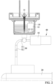
- FIG. 1 and FIG. 2 are perspective and partial, cross-sectional views of a combustion system in accordance with the present invention respectively.
- the combustion system of the present invention uses at least 90 wt% propylene glycol based liquid fuel.
- the combustion system includes a first fuel tank 10, a second fuel tank 20, and a drive unit 40.
- the first fuel tank 10 is for containing the propylene glycol based liquid fuel and includes a wick 11 inserted therein for transmitting the propylene glycol based liquid fuel in the first tank 10.
- the wick 11 is made of non wool material.
- the wick 11 is made of metal.
- the wick 11 is made of carbon fiber.
- the first fuel tank 10 also includes a sensing unit 12 configured to receive an activating signal and sense the liquid level of the propylene glycol based liquid fuel in the first fuel tank 10 and send a fuel replenishment signal accordingly, i.e. when the liquid level is at a low predetermined level
- the second fuel tank 20 is for containing the propylene glycol based liquid fuel.
- the second fuel tank 20 is connected to the first fuel tank 10 by a conduit system 30.
- the drive unit 40 is connected with the conduit system 30 and configured to receive the fuel replenishment signal so as to cause the propylene glycol based liquid fuel in the second fuel tank 20 to replenish the first fuel tank 10 through the conduit system 30 as well as to cool the wick 11.
- the sensing unit 12 can sense the liquid level of the propylene glycol based liquid fuel in the first fuel tank 10 in advance, and if the liquid level is low, it will send the fuel replenishment signal the driving unit 40.
- the signal causes the drive unit 40 to replenish the propylene glycol based liquid fuel in the second fuel tank 20 to flow into the first fuel tank 10 through the conduit system 30 until a high liquid level is achieved; on the contrary, a user can ignite the wick 11 if the liquid level is high.
- the fuel replenishing signal is sent to the drive unit 40, so that the drive unit 40 causes the propylene glycol based liquid fuel in the second fuel tank 20 to replenish the first fuel tank 10 through the conduit system 30, and the propylene glycol based liquid fuel from the second fuel tank 20 can not only supply fuel to and maintain the flame, but also cool the wick 11 heated by the flame so as to prevent the wick 11 from being overheated to affect the size and shape of the flame.
- the above efficacy is based in particular on the high flash point characteristics of propylene glycol based fuels, utilizing the propylene glycol based liquid fuel from the second fuel tank 20 to cool the wick 11 that has been heated by the flame and stabilize the flame size and shape, generally Ethanol or isopropanol based fuels cannot be used in this way, because their flash point is extremely low, and they are ignited upon contact with the wick 11 heated by the flame, and cannot be used to cool the wick 11 at all.
- the driving unit 40 is configured to receive a shutdown signal so as to pump the propylene glycol based liquid fuel in the first fuel tank 10 to the second fuel tank 20 by the conduit system 30.
- a shutdown signal so as to pump the propylene glycol based liquid fuel in the first fuel tank 10 to the second fuel tank 20 by the conduit system 30.
- the wick 11 when the wick 11 is in the ignited state, it will conduct the heat of the flame to the propylene glycol based liquid fuel in the first fuel tank 10.
- the propylene glycol based liquid fuel when the propylene glycol based liquid fuel is pumped to the second fuel tank 20 the wick 11 is also cooled, thereby better cooling the environment temperature. This is the characteristic of the high flash point of propylene glycol based fuel, and the propylene glycol based liquid fuel in the first fuel tank 10 is cooled by the propylene glycol based liquid fuel from the second fuel tank 20.
- the driving unit 40 when the driving unit 40 receives the shutdown signal and pumps the level of the propylene glycol based liquid fuel in the first fuel tank 10 to a height that cannot be transmitted by the wick 11 to generate a flame, or after the propylene glycol based liquid fuel in the first fuel tank 10 is completely pumped to the second fuel tank 20 (sensed by the sensing unit 12), it continues operating for a predetermined period of time so as to extract exhaust gas produced after the flame goes out through the conduit system 30.
- the volume of the first fuel tank 10 in this embodiment is smaller than the volume of the second fuel tank 20, and more preferably, the volume of the second fuel tank 20 is at least ten times larger than a volume of the first fuel tank 10.
- At least 90 wt% propylene glycol based liquid fuel used by the combustion system of the present invention can preferably contain 95 wt% propylene glycol.
- conduit system 30 of the present invention can include a first conduit connecting the first fuel tank 10 to the drive unit 40 and a second conduit 32 connecting the second fuel tank 20 to the drive unit 40.
- the drive unit 40 includes a motor 41 which is adapted to transmit the propylene glycol based liquid fuel in the second fuel tank 20 to the first fuel tank 10 through the conduit system 30, or to transmit the propylene glycol based liquid fuel in the first fuel tank 10 to the second fuel tank 20 through the conduit system 30.
- Fig. 3 shows a method flowchart of operating the combustion system using at least 90wt% propylene glycol based liquid fuel.
- the method includes preparing the combustion system, which has been described in detail above, and will not be repeated here for brevity; using the sensing unit 12 to receive an activating signal and sense the liquid level of the propylene glycol based liquid fuel in the first fuel tank 10 and send a fuel replenishment signal accordingly i.e.
- the propylene glycol based liquid fuel in the first fuel tank 10 reaches a height for igniting the wick 11 or maintaining the flame generated by the wick 11 in the ignited state, and it is worth noting that the wick 11 will heat up due to heat conduction in the ignited state, and the wick 11 can be cooled by supplementing the normal temperature propylene glycol-based liquid fuel from the second fuel tank 20 to achieve the cooling effect; and using the drive unit 40 to receive a shutdown signal and pump the propylene glycol based liquid fuel in the first fuel tank 10 to the second fuel tank 20 through the conduit system 30, and wherein the drive unit 40 continues operating for a predetermined period of time after receiving the shutdown signal and pumping the propylene glycol based liquid fuel in the first fuel tank 10 to the second fuel tank 20 so as to extract exhaust gas produced after the flame goes out.
- the operating method of the combustion system further includes the steps that the driving unit 40 receives the shutdown signal, and accordingly, the propylene glycol based liquid fuel in the first fuel tank 10 is pumped to the second fuel tank 20 through the conduit system 30 until the propylene glycol based liquid fuel in the first fuel tank 10 is low and the wick 11 cannot generate a flame, or the propylene glycol based liquid fuel in the first fuel tank 10 is completely pumped to the second fuel tank 20, so that the flame of the wick 11 goes out.
- the driving unit 40 After the driving unit 40 receives the shutdown signal and pumps the liquid level of the propylene glycol based liquid fuel in the first fuel tank 10 to a low level, or completely pumps the propylene glycol based liquid fuel in the first fuel tank 10 to the second fuel tank 20 (sensed by the sensing unit 12), it continues operating for a predetermined period of time to extract the exhaust gas generated by the extinguishment of the flame of the wick 11 through the conduit system 30.
Landscapes
- Engineering & Computer Science (AREA)
- Chemical & Material Sciences (AREA)
- Combustion & Propulsion (AREA)
- Mechanical Engineering (AREA)
- General Engineering & Computer Science (AREA)
- Feeding And Controlling Fuel (AREA)
- Regulation And Control Of Combustion (AREA)
Claims (12)
- Système de combustion utilisant un carburant liquide à base d'au moins 90 % en masse de propylène glycol, le système de combustion comprenant :un premier réservoir de carburant (10) pour contenir le carburant liquide à base de propylène glycol, une mèche (11) pour transmettre le carburant liquide à base de propylène glycol dans le premier réservoir de carburant (10),une unité de détection (12) conçue pour recevoir un signal d'activation et détecter le niveau de liquide du carburant liquide à base de propylène glycol dans le premier réservoir de carburant (10) et envoyer un signal de ravitaillement en carburant le cas échéant, un second réservoir de carburant (20) pour contenir le carburant liquide à base de propylène glycol, un système de conduite (30) reliant le premier réservoir de carburant (10) au second réservoir de carburant (20), et une unité d'entraînement (40) reliée au système de conduite (30) et conçue pour recevoir le signal de ravitaillement en carburant de manière à amener le carburant liquide à base de propylène glycol dans le second réservoir de carburant (20) pour ravitailler le premier réservoir de carburant (10) à travers le système de conduite (30) ainsi que pour refroidir la mèche (11), dans lequell'unité d'entraînement (40) est également conçue pour recevoir un signal d'arrêt de sorte à pomper le carburant liquide à base de propylène glycol du premier réservoir de carburant (10) dans le second réservoir de carburant (20).
- Système de combustion selon la revendication 1 précédente, dans lequel l'unité d'entraînement (40) est conçue pour poursuivre le pompage du carburant liquide à base de propylène glycol du premier réservoir de carburant (10) dans le second réservoir de carburant (20) pour une durée prédéterminée après avoir reçu le signal d'arrêt.
- Système de combustion selon la revendication 1, dans lequel le volume du premier réservoir de carburant (10) est inférieur au volume du second réservoir de carburant (20).
- Système de combustion selon la revendication 3 précédente, dans lequel le volume du second réservoir de carburant (20) est au moins dix fois supérieur à un volume du premier réservoir de carburant (10).
- Système de combustion selon la revendication 1, dans lequel le système de conduite (30) inclut une première conduite (31) reliant le premier réservoir de carburant (10) à l'unité d'entraînement (40) et une seconde conduite (32) reliant le second réservoir de carburant (20) à l'unité d'entraînement (40).
- Système de combustion selon la revendication 1, dans lequel l'unité d'entraînement (40) inclut un moteur (41).
- Système de combustion selon la revendication 1, dans lequel la mèche (11) est fabriquée en un matériau non laineux.
- Système de combustion selon la revendication 1, dans lequel la mèche (11) est fabriquée en métal.
- Système de combustion selon la revendication 1, dans lequel la mèche (11) est fabriquée en fibre de carbone.
- Procédé de fonctionnement d'un système de combustion utilisant un carburant liquide à base d'au moins 90 % en masse de propylène glycol, comprenant :
la préparation d'un système de combustion qui inclut :un premier réservoir de carburant (10) pour contenir le carburant liquide à base de propylène glycol avec une mèche (11) insérée dedans pour transmettre le carburant liquide à base de propylène glycol dans le premier réservoir de carburant (10), et une unité de détection (12) disposée dessus ;un second réservoir de carburant (20) pour contenir le carburant liquide à base de propylène glycol ;un système de conduite (30) reliant le premier réservoir de carburant (10) au second réservoir de carburant (20) ; etune unité d'entraînement (40) reliée au système de conduite (30)l'utilisation de l'unité de détection (12) pour recevoir un signal d'activation et détecter le niveau de liquide du carburant liquide à base de propylène glycol dans le premier réservoir de carburant (10) et envoyer un signal de ravitaillement en carburant le échéant ;l'utilisation de l'unité d'entraînement (40) pour recevoir le signal de ravitaillement en carburant de sorte à amener le carburant liquide à base de propylène glycol dans le second réservoir de carburant (20) pour ravitailler le premier réservoir de carburant (10) à travers le système de conduite (30), et pour amener le carburant liquide à base de propylène glycol du second réservoir de carburant (20) à refroidir la mèche (11) ; etl'utilisation de l'unité d'entraînement (40) pour recevoir un signal d'arrêt et pomper le carburant liquide à base de propylène glycol du premier réservoir de carburant (10) au second réservoir de carburant (20) à travers le système de conduite (30), et dans lequel l'unité d'entraînement (40) continue à fonctionner pendant une période prédéterminée après la réception du signal d'arrêt et le pompage du carburant liquide à base de propylène glycol du premier réservoir de carburant (10) au second réservoir de carburant (20) de sorte à extraire le gaz d'échappement produit après que la flamme s'éteint. - Système de combustion selon la revendication 7, dans lequel la mèche (11) est fabriquée en métal.
- Système de combustion selon la revendication 7, dans lequel la mèche (11) est fabriquée en fibre de carbone.
Applications Claiming Priority (1)
| Application Number | Priority Date | Filing Date | Title |
|---|---|---|---|
| TW111101720A TWI783858B (zh) | 2022-01-14 | 2022-01-14 | 燃燒系統及其運轉方法 |
Publications (3)
| Publication Number | Publication Date |
|---|---|
| EP4212772A1 EP4212772A1 (fr) | 2023-07-19 |
| EP4212772C0 EP4212772C0 (fr) | 2024-01-31 |
| EP4212772B1 true EP4212772B1 (fr) | 2024-01-31 |
Family
ID=81074263
Family Applications (1)
| Application Number | Title | Priority Date | Filing Date |
|---|---|---|---|
| EP22165657.2A Active EP4212772B1 (fr) | 2022-01-14 | 2022-03-30 | Système de combustion et procédé de fonctionnement correspondant |
Country Status (5)
| Country | Link |
|---|---|
| US (1) | US20230228414A1 (fr) |
| EP (1) | EP4212772B1 (fr) |
| JP (1) | JP3240815U (fr) |
| AU (1) | AU2022201378B2 (fr) |
| TW (1) | TWI783858B (fr) |
Family Cites Families (20)
| Publication number | Priority date | Publication date | Assignee | Title |
|---|---|---|---|---|
| US2286446A (en) * | 1939-10-20 | 1942-06-16 | Warner Mfg Co | Oil burner |
| US2509251A (en) * | 1948-08-20 | 1950-05-30 | Eugene D Rogers | Cigarette lighter |
| JPS5589014U (fr) * | 1978-12-13 | 1980-06-19 | ||
| JPS61147018A (ja) * | 1984-12-19 | 1986-07-04 | Matsushita Electric Ind Co Ltd | 強制給油式石油スト−ブ |
| IE57123B1 (en) * | 1985-11-18 | 1992-05-06 | David K Abbott | Votive light arrangement |
| DE3917530A1 (de) * | 1989-05-30 | 1990-12-06 | Wolfgang Birmelin | Opfertisch |
| US5302114A (en) * | 1991-10-31 | 1994-04-12 | Colgate-Palmolive Company | Cooking fuel container and burner |
| EP0540133B1 (fr) * | 1991-10-31 | 1996-06-19 | Colgate-Palmolive Company | Récipient de combustible pour la cuisson |
| CN1251159A (zh) * | 1997-01-24 | 2000-04-19 | 华莱士·布莱克 | 一次性燃油炉 |
| US6752622B2 (en) * | 2001-06-06 | 2004-06-22 | John Sherman Lesesne | Lamp and candle with a colored flame |
| US8062389B2 (en) * | 2006-02-08 | 2011-11-22 | The Board Of Regents Of The University Of Texas System | Low vapor pressure fuels for use in catalytic burners |
| WO2008045546A2 (fr) * | 2006-10-12 | 2008-04-17 | Stonewick, Inc. | Brûleur catalytique |
| JP5619024B2 (ja) * | 2008-12-26 | 2014-11-05 | ジーエイチティー・グローバル・ヒーティング・テクノロジーズ・ゲーエムベーハー | ジェットキャビティ触媒加熱装置 |
| WO2015026814A1 (fr) * | 2013-08-19 | 2015-02-26 | Masterson Enterprises, Inc. | Système et procédé de combustion de combustible solide |
| TW201510442A (zh) * | 2013-09-05 | 2015-03-16 | Pro Iroda Ind Inc | 燃燒裝置之燭芯 |
| EP2865734B1 (fr) * | 2013-10-25 | 2019-02-20 | Sara Carine Wilma Torfs | Utilisation d'un combustible sans danger dans des dispositifs à géométrie ouverte à effet de mèche |
| CN207230634U (zh) * | 2017-08-16 | 2018-04-13 | 常州恩图机电科技有限公司 | 一种风冷式智能酒精壁炉 |
| AU2019200674B1 (en) * | 2019-01-03 | 2020-01-23 | Pro-Iroda Industries, Inc. | Metallic wick |
| US10842146B1 (en) * | 2020-07-14 | 2020-11-24 | Joseph Pannullo | Insect repellent torch system with automatic fuel replenishment |
| US11994288B2 (en) * | 2020-10-27 | 2024-05-28 | Eric Champagne | Portable liquid fuel vaporizer |
-
2022
- 2022-01-14 TW TW111101720A patent/TWI783858B/zh active
- 2022-02-24 US US17/679,374 patent/US20230228414A1/en not_active Abandoned
- 2022-02-28 AU AU2022201378A patent/AU2022201378B2/en active Active
- 2022-03-30 EP EP22165657.2A patent/EP4212772B1/fr active Active
- 2022-12-09 JP JP2022004058U patent/JP3240815U/ja active Active
Also Published As
| Publication number | Publication date |
|---|---|
| EP4212772C0 (fr) | 2024-01-31 |
| JP3240815U (ja) | 2023-02-06 |
| TWI783858B (zh) | 2022-11-11 |
| TW202328594A (zh) | 2023-07-16 |
| US20230228414A1 (en) | 2023-07-20 |
| EP4212772A1 (fr) | 2023-07-19 |
| AU2022201378A1 (en) | 2023-08-03 |
| AU2022201378B2 (en) | 2024-02-29 |
Similar Documents
| Publication | Publication Date | Title |
|---|---|---|
| CA2805871C (fr) | Procedes de generation de gaz de combustibles fusibles | |
| US5928605A (en) | Device for dispensing a volatile substance | |
| US6033212A (en) | Lamp for dispensing volatile substances | |
| US20200049344A1 (en) | Solid Fuel Burning System and Method with Electronic Ignition | |
| EP0843561B1 (fr) | Dispositif de distribution d'une substance volatile | |
| US9709263B2 (en) | Fuel burning system and method | |
| WO1999023416A1 (fr) | Bougie a faible combustion | |
| US20130101946A1 (en) | Fuel Management of a Melting Fuel | |
| DK177438B3 (en) | Electronically controlled burner | |
| US9074763B2 (en) | Spill proof alcohol burner | |
| US20180335206A1 (en) | Wax Burning System | |
| EP4212772A1 (fr) | Système de combustion et procédé de fonctionnement correspondant | |
| WO2004044111A2 (fr) | Bougie resistant au vent | |
| CN116481025B (zh) | 燃烧装置及其运转方法 | |
| CA2625935C (fr) | Meche auto-extinguible rallumable pour chandelles et articles similaires | |
| EP2865734B1 (fr) | Utilisation d'un combustible sans danger dans des dispositifs à géométrie ouverte à effet de mèche | |
| US20150125797A1 (en) | Fuel Burning System and Method | |
| JPH0129381Y2 (fr) | ||
| US20130216966A1 (en) | Spill proof alcohol burner | |
| JPH0322533B2 (fr) | ||
| JPS6217160B2 (fr) | ||
| JP2000184843A (ja) | 害虫防除方法およびそれに用いられる害虫防除装置 | |
| JPS61202010A (ja) | 石油燃焼器の消火装置 | |
| JPS6113131B2 (fr) | ||
| JPH02110213A (ja) | 触媒燃焼型加熱器 |
Legal Events
| Date | Code | Title | Description |
|---|---|---|---|
| PUAI | Public reference made under article 153(3) epc to a published international application that has entered the european phase |
Free format text: ORIGINAL CODE: 0009012 |
|
| STAA | Information on the status of an ep patent application or granted ep patent |
Free format text: STATUS: REQUEST FOR EXAMINATION WAS MADE |
|
| 17P | Request for examination filed |
Effective date: 20230111 |
|
| AK | Designated contracting states |
Kind code of ref document: A1 Designated state(s): AL AT BE BG CH CY CZ DE DK EE ES FI FR GB GR HR HU IE IS IT LI LT LU LV MC MK MT NL NO PL PT RO RS SE SI SK SM TR |
|
| GRAP | Despatch of communication of intention to grant a patent |
Free format text: ORIGINAL CODE: EPIDOSNIGR1 |
|
| STAA | Information on the status of an ep patent application or granted ep patent |
Free format text: STATUS: GRANT OF PATENT IS INTENDED |
|
| INTG | Intention to grant announced |
Effective date: 20230907 |
|
| GRAS | Grant fee paid |
Free format text: ORIGINAL CODE: EPIDOSNIGR3 |
|
| GRAA | (expected) grant |
Free format text: ORIGINAL CODE: 0009210 |
|
| STAA | Information on the status of an ep patent application or granted ep patent |
Free format text: STATUS: THE PATENT HAS BEEN GRANTED |
|
| AK | Designated contracting states |
Kind code of ref document: B1 Designated state(s): AL AT BE BG CH CY CZ DE DK EE ES FI FR GB GR HR HU IE IS IT LI LT LU LV MC MK MT NL NO PL PT RO RS SE SI SK SM TR |
|
| REG | Reference to a national code |
Ref country code: GB Ref legal event code: FG4D Ref country code: CH Ref legal event code: EP |
|
| REG | Reference to a national code |
Ref country code: DE Ref legal event code: R096 Ref document number: 602022001732 Country of ref document: DE |
|
| REG | Reference to a national code |
Ref country code: IE Ref legal event code: FG4D |
|
| U01 | Request for unitary effect filed |
Effective date: 20240205 |
|
| U07 | Unitary effect registered |
Designated state(s): AT BE BG DE DK EE FI FR IT LT LU LV MT NL PT SE SI Effective date: 20240214 |
|
| U20 | Renewal fee for the european patent with unitary effect paid |
Year of fee payment: 3 Effective date: 20240327 |
|
| PG25 | Lapsed in a contracting state [announced via postgrant information from national office to epo] |
Ref country code: IS Free format text: LAPSE BECAUSE OF FAILURE TO SUBMIT A TRANSLATION OF THE DESCRIPTION OR TO PAY THE FEE WITHIN THE PRESCRIBED TIME-LIMIT Effective date: 20240531 |
|
| PG25 | Lapsed in a contracting state [announced via postgrant information from national office to epo] |
Ref country code: GR Free format text: LAPSE BECAUSE OF FAILURE TO SUBMIT A TRANSLATION OF THE DESCRIPTION OR TO PAY THE FEE WITHIN THE PRESCRIBED TIME-LIMIT Effective date: 20240501 |
|
| PG25 | Lapsed in a contracting state [announced via postgrant information from national office to epo] |
Ref country code: RS Free format text: LAPSE BECAUSE OF FAILURE TO SUBMIT A TRANSLATION OF THE DESCRIPTION OR TO PAY THE FEE WITHIN THE PRESCRIBED TIME-LIMIT Effective date: 20240430 Ref country code: HR Free format text: LAPSE BECAUSE OF FAILURE TO SUBMIT A TRANSLATION OF THE DESCRIPTION OR TO PAY THE FEE WITHIN THE PRESCRIBED TIME-LIMIT Effective date: 20240131 |
|
| PG25 | Lapsed in a contracting state [announced via postgrant information from national office to epo] |
Ref country code: ES Free format text: LAPSE BECAUSE OF FAILURE TO SUBMIT A TRANSLATION OF THE DESCRIPTION OR TO PAY THE FEE WITHIN THE PRESCRIBED TIME-LIMIT Effective date: 20240131 |
|
| PG25 | Lapsed in a contracting state [announced via postgrant information from national office to epo] |
Ref country code: RS Free format text: LAPSE BECAUSE OF FAILURE TO SUBMIT A TRANSLATION OF THE DESCRIPTION OR TO PAY THE FEE WITHIN THE PRESCRIBED TIME-LIMIT Effective date: 20240430 Ref country code: NO Free format text: LAPSE BECAUSE OF FAILURE TO SUBMIT A TRANSLATION OF THE DESCRIPTION OR TO PAY THE FEE WITHIN THE PRESCRIBED TIME-LIMIT Effective date: 20240430 Ref country code: IS Free format text: LAPSE BECAUSE OF FAILURE TO SUBMIT A TRANSLATION OF THE DESCRIPTION OR TO PAY THE FEE WITHIN THE PRESCRIBED TIME-LIMIT Effective date: 20240531 Ref country code: HR Free format text: LAPSE BECAUSE OF FAILURE TO SUBMIT A TRANSLATION OF THE DESCRIPTION OR TO PAY THE FEE WITHIN THE PRESCRIBED TIME-LIMIT Effective date: 20240131 Ref country code: GR Free format text: LAPSE BECAUSE OF FAILURE TO SUBMIT A TRANSLATION OF THE DESCRIPTION OR TO PAY THE FEE WITHIN THE PRESCRIBED TIME-LIMIT Effective date: 20240501 Ref country code: ES Free format text: LAPSE BECAUSE OF FAILURE TO SUBMIT A TRANSLATION OF THE DESCRIPTION OR TO PAY THE FEE WITHIN THE PRESCRIBED TIME-LIMIT Effective date: 20240131 |
|
| PG25 | Lapsed in a contracting state [announced via postgrant information from national office to epo] |
Ref country code: PL Free format text: LAPSE BECAUSE OF FAILURE TO SUBMIT A TRANSLATION OF THE DESCRIPTION OR TO PAY THE FEE WITHIN THE PRESCRIBED TIME-LIMIT Effective date: 20240131 |
|
| PG25 | Lapsed in a contracting state [announced via postgrant information from national office to epo] |
Ref country code: PL Free format text: LAPSE BECAUSE OF FAILURE TO SUBMIT A TRANSLATION OF THE DESCRIPTION OR TO PAY THE FEE WITHIN THE PRESCRIBED TIME-LIMIT Effective date: 20240131 |
|
| PG25 | Lapsed in a contracting state [announced via postgrant information from national office to epo] |
Ref country code: SM Free format text: LAPSE BECAUSE OF FAILURE TO SUBMIT A TRANSLATION OF THE DESCRIPTION OR TO PAY THE FEE WITHIN THE PRESCRIBED TIME-LIMIT Effective date: 20240131 |
|
| PG25 | Lapsed in a contracting state [announced via postgrant information from national office to epo] |
Ref country code: CZ Free format text: LAPSE BECAUSE OF FAILURE TO SUBMIT A TRANSLATION OF THE DESCRIPTION OR TO PAY THE FEE WITHIN THE PRESCRIBED TIME-LIMIT Effective date: 20240131 |
|
| PG25 | Lapsed in a contracting state [announced via postgrant information from national office to epo] |
Ref country code: SK Free format text: LAPSE BECAUSE OF FAILURE TO SUBMIT A TRANSLATION OF THE DESCRIPTION OR TO PAY THE FEE WITHIN THE PRESCRIBED TIME-LIMIT Effective date: 20240131 |
|
| PG25 | Lapsed in a contracting state [announced via postgrant information from national office to epo] |
Ref country code: SM Free format text: LAPSE BECAUSE OF FAILURE TO SUBMIT A TRANSLATION OF THE DESCRIPTION OR TO PAY THE FEE WITHIN THE PRESCRIBED TIME-LIMIT Effective date: 20240131 Ref country code: SK Free format text: LAPSE BECAUSE OF FAILURE TO SUBMIT A TRANSLATION OF THE DESCRIPTION OR TO PAY THE FEE WITHIN THE PRESCRIBED TIME-LIMIT Effective date: 20240131 Ref country code: RO Free format text: LAPSE BECAUSE OF FAILURE TO SUBMIT A TRANSLATION OF THE DESCRIPTION OR TO PAY THE FEE WITHIN THE PRESCRIBED TIME-LIMIT Effective date: 20240131 Ref country code: CZ Free format text: LAPSE BECAUSE OF FAILURE TO SUBMIT A TRANSLATION OF THE DESCRIPTION OR TO PAY THE FEE WITHIN THE PRESCRIBED TIME-LIMIT Effective date: 20240131 |
|
| REG | Reference to a national code |
Ref country code: DE Ref legal event code: R097 Ref document number: 602022001732 Country of ref document: DE |
|
| PG25 | Lapsed in a contracting state [announced via postgrant information from national office to epo] |
Ref country code: MC Free format text: LAPSE BECAUSE OF FAILURE TO SUBMIT A TRANSLATION OF THE DESCRIPTION OR TO PAY THE FEE WITHIN THE PRESCRIBED TIME-LIMIT Effective date: 20240131 |
|
| PG25 | Lapsed in a contracting state [announced via postgrant information from national office to epo] |
Ref country code: MC Free format text: LAPSE BECAUSE OF FAILURE TO SUBMIT A TRANSLATION OF THE DESCRIPTION OR TO PAY THE FEE WITHIN THE PRESCRIBED TIME-LIMIT Effective date: 20240131 |
|
| PLBE | No opposition filed within time limit |
Free format text: ORIGINAL CODE: 0009261 |
|
| STAA | Information on the status of an ep patent application or granted ep patent |
Free format text: STATUS: NO OPPOSITION FILED WITHIN TIME LIMIT |
|
| 26N | No opposition filed |
Effective date: 20241101 |
|
| PG25 | Lapsed in a contracting state [announced via postgrant information from national office to epo] |
Ref country code: IE Free format text: LAPSE BECAUSE OF NON-PAYMENT OF DUE FEES Effective date: 20240330 |
|
| PG25 | Lapsed in a contracting state [announced via postgrant information from national office to epo] |
Ref country code: IE Free format text: LAPSE BECAUSE OF NON-PAYMENT OF DUE FEES Effective date: 20240330 |
|
| U20 | Renewal fee for the european patent with unitary effect paid |
Year of fee payment: 4 Effective date: 20250311 |
|
| PG25 | Lapsed in a contracting state [announced via postgrant information from national office to epo] |
Ref country code: CY Free format text: LAPSE BECAUSE OF FAILURE TO SUBMIT A TRANSLATION OF THE DESCRIPTION OR TO PAY THE FEE WITHIN THE PRESCRIBED TIME-LIMIT; INVALID AB INITIO Effective date: 20220330 |
|
| REG | Reference to a national code |
Ref country code: CH Ref legal event code: H13 Free format text: ST27 STATUS EVENT CODE: U-0-0-H10-H13 (AS PROVIDED BY THE NATIONAL OFFICE) Effective date: 20251023 |
|
| PG25 | Lapsed in a contracting state [announced via postgrant information from national office to epo] |
Ref country code: TR Free format text: LAPSE BECAUSE OF FAILURE TO SUBMIT A TRANSLATION OF THE DESCRIPTION OR TO PAY THE FEE WITHIN THE PRESCRIBED TIME-LIMIT Effective date: 20240131 |
|
| PG25 | Lapsed in a contracting state [announced via postgrant information from national office to epo] |
Ref country code: CH Free format text: LAPSE BECAUSE OF NON-PAYMENT OF DUE FEES Effective date: 20250331 |
|
| U20 | Renewal fee for the european patent with unitary effect paid |
Year of fee payment: 5 Effective date: 20260304 |
|
| PGFP | Annual fee paid to national office [announced via postgrant information from national office to epo] |
Ref country code: GB Payment date: 20260324 Year of fee payment: 5 |