EP4212829A1 - Procédé et dispositif de mesure pour déterminer une grandeur de mesure concernant un débit - Google Patents
Procédé et dispositif de mesure pour déterminer une grandeur de mesure concernant un débit Download PDFInfo
- Publication number
- EP4212829A1 EP4212829A1 EP23150087.7A EP23150087A EP4212829A1 EP 4212829 A1 EP4212829 A1 EP 4212829A1 EP 23150087 A EP23150087 A EP 23150087A EP 4212829 A1 EP4212829 A1 EP 4212829A1
- Authority
- EP
- European Patent Office
- Prior art keywords
- signal
- received signals
- maximum
- determined
- measured variable
- Prior art date
- Legal status (The legal status is an assumption and is not a legal conclusion. Google has not performed a legal analysis and makes no representation as to the accuracy of the status listed.)
- Pending
Links
Images


Classifications
-
- G—PHYSICS
- G01—MEASURING; TESTING
- G01F—MEASURING VOLUME, VOLUME FLOW, MASS FLOW OR LIQUID LEVEL; METERING BY VOLUME
- G01F1/00—Measuring the volume flow or mass flow of fluid or fluent solid material wherein the fluid passes through a meter in a continuous flow
- G01F1/66—Measuring the volume flow or mass flow of fluid or fluent solid material wherein the fluid passes through a meter in a continuous flow by measuring frequency, phase shift or propagation time of electromagnetic or other waves, e.g. using ultrasonic flowmeters
-
- G—PHYSICS
- G01—MEASURING; TESTING
- G01F—MEASURING VOLUME, VOLUME FLOW, MASS FLOW OR LIQUID LEVEL; METERING BY VOLUME
- G01F1/00—Measuring the volume flow or mass flow of fluid or fluent solid material wherein the fluid passes through a meter in a continuous flow
- G01F1/66—Measuring the volume flow or mass flow of fluid or fluent solid material wherein the fluid passes through a meter in a continuous flow by measuring frequency, phase shift or propagation time of electromagnetic or other waves, e.g. using ultrasonic flowmeters
- G01F1/667—Arrangements of transducers for ultrasonic flowmeters; Circuits for operating ultrasonic flowmeters
-
- G—PHYSICS
- G01—MEASURING; TESTING
- G01F—MEASURING VOLUME, VOLUME FLOW, MASS FLOW OR LIQUID LEVEL; METERING BY VOLUME
- G01F1/00—Measuring the volume flow or mass flow of fluid or fluent solid material wherein the fluid passes through a meter in a continuous flow
- G01F1/66—Measuring the volume flow or mass flow of fluid or fluent solid material wherein the fluid passes through a meter in a continuous flow by measuring frequency, phase shift or propagation time of electromagnetic or other waves, e.g. using ultrasonic flowmeters
- G01F1/663—Measuring the volume flow or mass flow of fluid or fluent solid material wherein the fluid passes through a meter in a continuous flow by measuring frequency, phase shift or propagation time of electromagnetic or other waves, e.g. using ultrasonic flowmeters by measuring Doppler frequency shift
-
- G—PHYSICS
- G01—MEASURING; TESTING
- G01F—MEASURING VOLUME, VOLUME FLOW, MASS FLOW OR LIQUID LEVEL; METERING BY VOLUME
- G01F1/00—Measuring the volume flow or mass flow of fluid or fluent solid material wherein the fluid passes through a meter in a continuous flow
- G01F1/704—Measuring the volume flow or mass flow of fluid or fluent solid material wherein the fluid passes through a meter in a continuous flow using marked regions or existing inhomogeneities within the fluid stream, e.g. statistically occurring variations in a fluid parameter
- G01F1/708—Measuring the time taken to traverse a fixed distance
- G01F1/7082—Measuring the time taken to traverse a fixed distance using acoustic detecting arrangements
-
- G—PHYSICS
- G01—MEASURING; TESTING
- G01F—MEASURING VOLUME, VOLUME FLOW, MASS FLOW OR LIQUID LEVEL; METERING BY VOLUME
- G01F1/00—Measuring the volume flow or mass flow of fluid or fluent solid material wherein the fluid passes through a meter in a continuous flow
- G01F1/704—Measuring the volume flow or mass flow of fluid or fluent solid material wherein the fluid passes through a meter in a continuous flow using marked regions or existing inhomogeneities within the fluid stream, e.g. statistically occurring variations in a fluid parameter
- G01F1/708—Measuring the time taken to traverse a fixed distance
- G01F1/712—Measuring the time taken to traverse a fixed distance using auto-correlation or cross-correlation detection means
-
- G—PHYSICS
- G01—MEASURING; TESTING
- G01P—MEASURING LINEAR OR ANGULAR SPEED, ACCELERATION, DECELERATION, OR SHOCK; INDICATING PRESENCE, ABSENCE, OR DIRECTION, OF MOVEMENT
- G01P5/00—Measuring speed of fluids, e.g. of air stream; Measuring speed of bodies relative to fluids, e.g. of ship, of aircraft
- G01P5/24—Measuring speed of fluids, e.g. of air stream; Measuring speed of bodies relative to fluids, e.g. of ship, of aircraft by measuring the direct influence of the streaming fluid on the properties of a detecting acoustical wave
- G01P5/245—Measuring speed of fluids, e.g. of air stream; Measuring speed of bodies relative to fluids, e.g. of ship, of aircraft by measuring the direct influence of the streaming fluid on the properties of a detecting acoustical wave by measuring transit time of acoustical waves
-
- G—PHYSICS
- G01—MEASURING; TESTING
- G01S—RADIO DIRECTION-FINDING; RADIO NAVIGATION; DETERMINING DISTANCE OR VELOCITY BY USE OF RADIO WAVES; LOCATING OR PRESENCE-DETECTING BY USE OF THE REFLECTION OR RERADIATION OF RADIO WAVES; ANALOGOUS ARRANGEMENTS USING OTHER WAVES
- G01S15/00—Systems using the reflection or reradiation of acoustic waves, e.g. sonar systems
- G01S15/02—Systems using the reflection or reradiation of acoustic waves, e.g. sonar systems using reflection of acoustic waves
- G01S15/06—Systems determining the position data of a target
- G01S15/08—Systems for measuring distance only
- G01S15/10—Systems for measuring distance only using transmission of interrupted, pulse-modulated waves
-
- G—PHYSICS
- G01—MEASURING; TESTING
- G01F—MEASURING VOLUME, VOLUME FLOW, MASS FLOW OR LIQUID LEVEL; METERING BY VOLUME
- G01F15/00—Details of, or accessories for, apparatus of groups G01F1/00 - G01F13/00 insofar as such details or appliances are not adapted to particular types of such apparatus
- G01F15/02—Compensating or correcting for variations in pressure, density or temperature
- G01F15/022—Compensating or correcting for variations in pressure, density or temperature using electrical means
- G01F15/024—Compensating or correcting for variations in pressure, density or temperature using electrical means involving digital counting
-
- G—PHYSICS
- G01—MEASURING; TESTING
- G01F—MEASURING VOLUME, VOLUME FLOW, MASS FLOW OR LIQUID LEVEL; METERING BY VOLUME
- G01F15/00—Details of, or accessories for, apparatus of groups G01F1/00 - G01F13/00 insofar as such details or appliances are not adapted to particular types of such apparatus
- G01F15/06—Indicating or recording devices
- G01F15/061—Indicating or recording devices for remote indication
- G01F15/063—Indicating or recording devices for remote indication using electrical means
-
- G—PHYSICS
- G01—MEASURING; TESTING
- G01F—MEASURING VOLUME, VOLUME FLOW, MASS FLOW OR LIQUID LEVEL; METERING BY VOLUME
- G01F25/00—Testing or calibration of apparatus for measuring volume, volume flow or liquid level or for metering by volume
- G01F25/10—Testing or calibration of apparatus for measuring volume, volume flow or liquid level or for metering by volume of flowmeters
-
- G—PHYSICS
- G01—MEASURING; TESTING
- G01P—MEASURING LINEAR OR ANGULAR SPEED, ACCELERATION, DECELERATION, OR SHOCK; INDICATING PRESENCE, ABSENCE, OR DIRECTION, OF MOVEMENT
- G01P5/00—Measuring speed of fluids, e.g. of air stream; Measuring speed of bodies relative to fluids, e.g. of ship, of aircraft
- G01P5/24—Measuring speed of fluids, e.g. of air stream; Measuring speed of bodies relative to fluids, e.g. of ship, of aircraft by measuring the direct influence of the streaming fluid on the properties of a detecting acoustical wave
Definitions
- the invention relates to a method for determining a measured variable relating to the flow of a fluid through a measuring tube using a measuring device, with an ultrasonic signal being emitted for two propagation directions in each case by a transmitting ultrasonic transducer of the measuring device and transmitted via the fluid to a receiving ultrasonic transducer of the measuring device, with a received signal for the respective propagation direction is detected by the respective receiving ultrasonic transducer, with a cross-correlation of the received signals for the two propagation directions or a cross-correlation of processing signals, each of which depends on one of the received signals or on a partial signal of the respective received signal, depending on the position of the main maximum Runtime difference between the runtimes of the respective ultrasonic signal for the respective direction of propagation from the respective transmitting ultrasonic transducer to the respective receiving ultrasonic transducer is determined, after which the measured variable is determined as a function of the runtime difference, with the transmitting ultrasonic transducer being activated in each case with an ex
- the publication proposes to improve the time resolution DE 10 2009 046 562 A1 proposes using a transmission pulse with a changing carrier frequency for both transmission directions. Now the frequency change courses of the received signals determined and correlated with each other for the two directions of propagation, a transit time difference can be determined with good time resolution.
- excitation with a variable excitation frequency is technically relatively complex and, in addition, for at least part of the excitation interval, excitation must be carried out at a frequency that differs from the resonant frequency, which means that greater energy expenditure is required to achieve the same excitation amplitudes.
- excitation with a carrier frequency that changes over time is not suitable for all measuring devices. If, for example, the fluid is to be excited indirectly by first exciting a Lamb wave in a pipe wall, which in turn excites compression waves in the fluid, different excitation frequencies lead to different Rayleigh angles and thus to different propagation paths of the compression wave in the fluid, which is why it is not or at least it is not readily possible to determine a flow rate from the received signals resulting from this.
- the invention is therefore based on the object of specifying a possibility of determining a transit time difference, which is used to determine a measured variable relating to the flow of a fluid, with high time resolution, the problems explained above resulting from a change in the carrier frequency within the excitation pulse , should at least be largely avoided.
- the object is achieved according to the invention by a method of the type mentioned at the outset, in which, on the one hand, the excitation signal has a fixed carrier frequency, the excitation signal has a phase jump and/or an envelope with a plurality of maxima spaced apart in time, and/or in which, on the other hand, when a triggering condition is met, the Fulfillment depends on the level of the main maximum and/or at least one secondary maximum of the cross-correlation, the determination of the measured variable is modified compared to a normal operating mode and/or a message is output to a user of the measuring device and/or a further device external to the measuring device.
- the proposed procedure makes it possible to determine the propagation time difference robustly and with high resolution even without changing the carrier frequency of the excitation signal, which means that the measured variable can also be determined robustly and with good accuracy.
- the cross-correlation already takes into account the phase position of the received signals, which results in a high time resolution for the transit time difference. If the excitation signal were to be emitted permanently as a periodic signal, the propagation time difference could not be determined unequivocally, since several maxima of the same magnitude would occur at intervals of the period of the excitation signal.
- the use of a finitely long excitation or thus also a time-varying envelope already leads to a clear main maximum of the cross-correlation resulting from interference-free or sufficiently low-interference measurements and the secondary maxima have a noticeably lower height than the main maximum, which means that a clear transit time difference can be determined is.
- phase jump in the excitation signal leads to a phase jump in the received signals, with the result that these no longer overlap in phase synchronization in some areas after such a shift.
- one Shifting the maxima of the envelopes of the received signals, which result from the choice of the described envelope for the excitation signal, relative to one another leads to a reduction in the height of the secondary maxima. As a result, the measurement as a whole is considerably less susceptible to interference.
- the trigger condition can also be used for other purposes, for example to further improve the measurement accuracy, to detect aging processes and the like, particularly when a phase jump or an envelope with a plurality of maxima spaced apart in time is used.
- Checking the triggering condition is also useful in order to carry out quality control during manufacture and/or after installation of the measuring device and, for example, to issue a message if the triggering condition is met that the measuring device or its installation does not meet specified quality requirements.
- the main peak is the global peak of the cross-correlation, while the side peaks are only local peaks. If the measurement is disturbed, e.g. due to noise and/or a limited temporal resolution of the acquisition of the received signals, however, received signals result in the height of a local maximum for their cross-correlation, which would be a secondary maximum in the case of undisturbed measurement, the height of that local maximum which would be the main maximum if the measurement were undisturbed. In the present case, this is also referred to as incorrect identification of the main maximum or of its position. Corresponding disturbances are to be suppressed or at least recognized by the procedure described.
- the ultrasonic transducer that is used as the transmitting ultrasonic transducer for the first propagation direction can be used as the receiving ultrasonic transducer for the second propagation direction and/or the ultrasonic transducer that is used as the receiving ultrasonic transducer for the first propagation direction can be used for the second Direction of propagation are used as a transmitting ultrasonic transducer.
- the inventive method can thus with exactly two ultrasonic transducers are carried out, which are each used for one of the propagation directions as a transmitting ultrasonic transducer and for the other propagation direction as a receiving ultrasonic transducer.
- an ultrasonic transducer for emitting the ultrasonic signal and/or for receiving the received signal for the second direction of propagation, which is not used in the context of the measurement for the first direction of propagation.
- the same ultrasonic transducer can be used for the first propagation direction and the second propagation direction to transmit the respective ultrasonic signal, with, for example, a further ultrasonic transducer located upstream of this ultrasonic transducer being used as a receiving ultrasonic transducer for the first propagation direction and a further ultrasonic transducer arranged downstream of this ultrasonic transducer for the second propagation direction another ultrasonic transducer.
- the ultrasonic transducers can be arranged in or on the measuring tube and excite the fluid either directly or indirectly.
- Indirect excitation can take place, for example, by first exciting a guided wave, for example a Lamb wave, in the measuring tube wall, which excites compression waves in the fluid along its propagation path.
- reception can also take place either directly by the receiving ultrasonic transducer or indirectly, for example via a pipe wall.
- a flow rate of the fluid and/or a volume flow can be determined as a measured variable.
- the respective processing signal or an intermediate signal from which the processing signal is determined can be generated or selected, for example, in that only parts of the measured values of the respective received signal are taken into account, for example only those measured values that occur during a specific sub-interval of the time interval during which the received signal was detected.
- the computing effort and thus the energy requirement for calculating the cross-correlation can be reduced in particular.
- upsampling, interpolation, filtering and/or scaling for example, can take place as part of the determination of the respective processing signal.
- the envelope can, in the simplest case, be a square-wave function, ie it can be used to switch the excitation signal on and off.
- envelopes with a complex shape for example pulse sequences or envelopes which have different gradients in sections, can also be used.
- the amplitude profile of the excitation signal can be predetermined, for example, by first specifying or generating the excitation signal with a fixed amplitude and then amplitude modulating it with a separately specified envelope.
- an excitation signal with the desired amplitude curve or with the desired envelope can be generated or specified directly, for example.
- the excitation signal can in particular have the resonant frequency of the transmitting and/or the receiving ultrasonic transducer.
- the carrier frequency can be chosen such that the maximum amplitude of the received signal results for a given amplitude of the excitation.
- the selection of the carrier frequency can also serve to maximize the size of phase jumps in the received signal.
- the evaluation of the triggering condition can be used to identify distortions in one of the received signals, such distortions leading in particular to a reduction in the height of the main maximum, since in this case the received signals have forms that differ significantly from one another.
- Such distortions can result, for example, from the fact that one of the ultrasonic transducers or the associated electronics is damaged, or that the components are incorrectly matched to one another.
- Distortions can also result from disturbed sound transmission paths, for example if the ultrasonic transducers are not correctly coupled to the measuring tube or other components or if there is air, particles or the like in the measuring tube.
- a lack of electromagnetic compatibility of components of the measuring device or of components arranged in the vicinity of the measuring device, for example due to attempts to manipulate a flow meter, can also occur corresponding distortions or a lowering of the height of the main maximum.
- the height of the secondary maximum in particular compared to the height of the main maximum, can be evaluated in particular in order to assess how robustly the main maximum was recognized in the current measurement. A potential misidentification of the main maximum can thus be recognized and, for example, the measurement can be repeated as required.
- the determination of the measured variable can be modified compared to the normal operating mode in such a way that on the one hand the received signals are discarded and either a previously determined measured variable is used as the current measured variable or the determination of the received signals is repeated to provide new received signals, with the determination of the new ones Received signals are either unchanged compared to the determination of the received signals or with at least one changed determination parameter, and the measured variable is determined on the basis of the new received signals, and/or that, on the other hand, the transit time difference is determined depending on the position of one of the secondary maxima of the cross-correlation and/or a determination rule is modified to determine the measured variable from the transit time difference.
- the triggering condition can be met due to disturbances or manipulations, which can be recognized, for example, by the presence of very similar heights of the main maximum and at least one secondary maximum and/or a significantly reduced height of the main maximum. In this case it is advisable to discard the measurement. Depending on the timing of the measurement in normal operation, there may be sufficient time reserve to repeat the measurements.
- the carrier frequency of the excitation signal and/or the size of the phase jump can be modified as acquisition parameters, which will be discussed later.
- the envelope for example the time interval between the maxima and/or the maximum amplitude, and/or to adapt a sensitivity of the detection of the received signals.
- the previously determined measured variable can continue to be used instead of a newly determined measured variable, which can be useful, for example, if a measured variable is used as a measured variable determined volume flow should be integrated over time or something similar.
- a high flow rate of the fluid through the measuring tube can also lead to the fulfillment of the triggering condition.
- This can be recognized, for example, by a relatively uniform reduction in the height of the main and secondary maxima.
- it may be useful to adapt the determination rule for determining the measured variable from the transit time difference for example if, based on a known flow geometry in the measuring tube, it can be assumed that, due to a change in the flow profile at high flow rates, there is a different relationship between the transit time difference, which typically primarily results from the flow velocity in a certain area of the measuring tube and the flow rate. For example, depending on whether the triggering condition is met or not, a different scaling factor can be used or a different look-up table, a different mathematical relationship or the like.
- the main maximum and at least one secondary maximum have relatively similar heights, ie, for example, a height difference or quotient falls below a limit value.
- a height difference or quotient falls below a limit value.
- the lowering of the main maximum speaks for a high flow rate and at the same time that from the Position of the main maximum determined running time for a low flow.
- the received signals can be determined a second time after a first determination of the received signals, with the carrier frequency of the excitation signal and/or the size of the phase jump being compared the first determination is changed.
- the transit time difference can then be determined as a function of the measurement data from the second determination.
- the resonant frequency of one of the ultrasonic transducers or both ultrasonic transducers can shift and/or a transfer function for an entire transmission path between the ultrasonic transducers can change. This can also change the optimal measurement conditions, which can be detected by checking the trigger condition or the spectral condition. The optimal measurement conditions can then be restored by adjusting the carrier frequency or the magnitude of the phase jump.
- an excitation at the resonant frequency can be desired in order to achieve a maximum amplitude of the received signal for a given amplitude of the excitation. If, for example, the resonant frequency of an ultrasonic transducer shifts or the transfer function changes, this can lead to a reduced amplitude of the received signals, which, if not normalized of the received signals or the cross-correlation takes place, also lowers the level of the main and secondary maxima of the cross-correlation. This can be recognized by the triggering condition and thus the excitation signal to be used can be redefined, in particular a corresponding carrier frequency can be selected in order to again achieve the maximum amplitude.
- the spectral composition By evaluating the spectral composition within the framework of the spectral condition, it can be recognized, for example, when the ultrasonic signals are excited at a frequency that does not correspond to the resonant frequency of the transmitting or the receiving ultrasonic transducer. As, for example, in the publication cited at the outset DE 10 2009 046 562 A1 is explained, the result in this case is a superimposition of the excitation frequency and the resonance frequency, which can be easily recognized in the spectral composition.
- Fulfillment of the spectral condition can depend, for example, on which frequencies in which frequency range have the maximum amplitude in the respective received signal or in a selected time segment of the respective received signal. e.g. B. in the decay phase of the received signal dominant frequencies that do not correspond to the excitation or carrier frequency, this indicates a side-resonant excitation.
- Such a spectral condition can be evaluated, for example, by transforming the received signal or the time segment into the frequency domain and searching for maxima there. If the frequency resolution is not too high, it can be useful to improve the robustness to combine adjacent frequency ranges into larger frequency ranges, which is also referred to as binning.
- the received signals for the propagation directions and the respective cross-correlation to be determined several times in succession, with a time profile of the height of the main maximum and/or at least one of the secondary maxima of the cross-correlation and/or a time profile of a processing result, which depends on the heights of the main maximum and at least one of the secondary maxima, is detected, with the fulfillment of the triggering condition depending on the respective course over time.
- aging processes of components can be detected by detecting the course over time of at least one of the variables mentioned.
- This can be useful, for example, to adjust the operation of the measuring device as the components age and/or to send a maintenance-related notice to a user or an external device, for example, in good time before corresponding aging leads to an unacceptable deterioration in the measurement accuracy the manufacturer of the measuring device or a measuring service company.
- taking into account the course of at least one of the variables mentioned can also be advantageous in order to be able to distinguish between a change in the variables mentioned due to aging and a sudden change, for example due to a specific fault or an attempt at manipulation.
- a test ultrasonic signal can be emitted several times for at least one of the propagation directions by the respective transmitting ultrasonic transducer and transmitted via the fluid to the respective receiving ultrasonic transducer, with a respective test reception signal being detected via the respective receiving ultrasonic transducer, with the respective transmitting ultrasonic transducer for the emission of the respective test ultrasonic signal is controlled in each case with a test excitation signal, in particular amplitude-modulated by the envelope, with the test excitation signals differing from one another with regard to their carrier frequency and/or the size of their phase shift, with that test excitation signal being selected as the excitation signal for determining the propagation time difference, for the the maximum phase jump and/or the maximum separation of local maxima of an envelope of the test reception signal result in the resultant test reception signal.
- a measure for the separation of the maxima of the envelope can depend on the time interval between the maxima and/or on a minimum height of the envelope between the maxima. In particular, this measure can depend on the ratio of this minimum height to the height of one of the neighboring local maxima, in particular the lower of the maxima.
- a large phase jump in the received signals or a strong separation of the local maxima of the envelopes of the received signals leads to the secondary maxima being strongly suppressed in the case of a cross-correlation of received signals or processing signals determined from them.
- the described leads Proceed in particular to select as the excitation signal that of the test excitation signals when the main maximum stands out particularly clearly from the secondary maxima, as a result of which a particularly robust determination of the propagation time difference and thus the measured variable is possible.
- the described selection of the excitation signal from a plurality of test excitation signals can be carried out once to calibrate the measuring device, for example immediately after it has been manufactured or installed. However, it is also possible to repeat this selection under specific conditions, for example after the triggering condition and/or the spectral condition has been met and/or after specific periods of time or after a specific degree of aging has been determined.
- the size of the phase jump can be determined by carrying out a Fourier transformation for a number of windows of the respective test reception signal.
- a phase can be determined for each of the frequencies contained in the test reception signal for each of these windows, ie for the different time segments of the test reception signal, by means of Fourier transformations.
- a strong change in the phase of the dominant frequency between adjacent windows corresponds to the phase jump, which can be calculated directly by subtracting the relative phase angles.
- Fulfillment of the triggering condition can depend on the difference and/or the quotient of the height of the main maximum and the height of one of the secondary maxima, in particular the highest secondary maximum.
- the triggering condition can depend on a comparison of one of these variables with a limit value. If the main maximum is absolutely or relatively much larger than all secondary maxima or the highest secondary maximum, this speaks for a high robustness of the detection of the main maximum. Otherwise, the triggering condition can be met, for example, to indicate disturbances that could lead to the main maximum not being clearly identifiable, or to improve the robustness by changing the determination of the measured variable.
- the respective processing signal can be determined by normalizing the respective received signal or a respective intermediate signal determined from the received signal.
- the level of the main maximum and/or the secondary maximum of the cross-correlation can be determined after a normalization of the cross-correlation.
- Normalization scales the values of the respective received signal or processing signal or the cross-correlation with a predetermined factor. For example, a particular value, e.g., the respective global maximum, can be scaled to a predetermined value, e.g., one, and the further values can be scaled with the same scaling factor.
- all values can be scaled with a scaling factor that depends on the amplitudes of the two auto-correlations of the two cross-correlated reception and processing signals.
- a scaling factor that is inversely proportional to the square root of the product of the amplitudes of the autocorrelations can be used.
- a suitable normalization means that the cross product is essentially independent of the amplitude of the input signals and thus only affects a similarity or time shift of the input signals to one another.
- the intermediate signal can be determined, for example, by upsampling, interpolating and/or filtering the respective received signal and/or by selecting a partial signal from the respective received signal, in particular to reduce the computing effort and thus the energy consumption of the calculation.
- the invention relates to a measuring device for determining a measured variable relating to the flow of a fluid through a measuring tube, comprising a measuring tube carrying the fluid, at least two ultrasonic transducers arranged in or on the measuring tube and a control device which is used to control the ultrasonic transducers for detection of received signals via the ultrasonic transducer and for determining the measured variable as a function of the received signals, the control device being set up to carry out the method according to the invention.
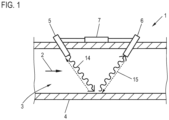
- a measuring device 1 for determining a measured variable relating to the flow of a fluid 3 through a measuring tube 4, in particular a flow velocity or a flow volume.
- the fluid 3 flows through the measuring tube 4 in the direction shown by the arrow 2.
- a control device 7 controls the ultrasonic transducer 5 as the transmitting ultrasonic transducer in order to emit the ultrasonic signal 14 in the direction of flow, which after being reflected on the pipe wall by the ultrasonic transducer 6 is received, the corresponding received signal being detected by the control device 7 via the receiving ultrasonic transducer 6 .
- control device 7 controls the ultrasonic transducer 6 as a transmitting ultrasonic transducer in order to transmit the ultrasonic signal 15 counter to the direction of flow to the now receiving ultrasonic transducer 5, via which the control device 7 detects a corresponding received signal.
- a transit time difference between the transit time of the ultrasonic signal 14 from the ultrasonic transducer 5 to the ultrasonic transducer 6 and the transit time of the ultrasonic signal 15 from the ultrasonic transducer 6 to the ultrasonic transducer 5 can be determined, which, as is well known, depends on the flow velocity of the fluid 3 is correlated, so that with a known measuring tube geometry, a volume flow for the fluid 3 can be determined.
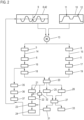
- control device 7 for determining a measured variable 24, for example the flow volume Details of a method implemented by the control device 7 for determining a measured variable 24, for example the flow volume, are provided below with additional reference to FIG 2 explained.
- an excitation signal 8, 42 with a fixed carrier frequency and amplitude is provided, after which an amplitude modulation 13 of the excitation signal 8 with an envelope 10 takes place.
- the excitation signal 8 , 42 directly with an amplitude that varies over time and that is specified by a corresponding envelope 10 .
- the amplitude-modulated excitation signal 8, 42 is fed, typically in succession, to the ultrasonic transducers 5, 6, as a result of which they emit the ultrasonic signals 14, 15, the reception of which at the respective other ultrasonic transducer 5, 6 results in the provision of the respective received signals 16, 17 to the control device 7 allows.
- a processing signal 18, 19 can first be determined from the respective received signal 16, 17, for example by upsampling, filtering and/or scaling, in particular normalization.
- a partial signal can be selected from the respective received signal to determine the processing signal.
- a cross-correlation 20 of the received signals 16, 17 or of the processing signals 18, 19 then takes place.
- the integral can also be expressed as a sum over the individual samples.
- the envelope 10 is a square-wave function, so that the excitation signal 8, 42 used in each case is output to the respective ultrasonic transducer 5, 6 with a fixed amplitude for a few cycles and the activation is then terminated abruptly.
- a normal sinusoidal oscillation is used as the excitation signal 42 .
- the X-axis 40 indicates the course over time in ps and the Y-axis 41 indicates the amplitude. Due to the transmission properties of a normal measurement path, the use of this excitation signal 42 results in the received signal 43, for example.
- corresponding disturbances can generally be detected by evaluating a triggering condition 27 and a corresponding response can be made, so that in principle a robust determination of the measured variable is also possible when using the excitation signal 42 .
- an approach will first be explained in order to reduce the risk of such a measurement error from the outset.
- an excitation signal 8 can be used which has a phase jump 9, in the example of 180°.
- phase jump 9 in the example of 180°.
- other sizes of the phase jump for example 90° or 270° or values in between, could also be used.
- a phase jump around 180° is particularly easy to implement because it can be generated, for example, by inverting the signal at the zero crossing.
- the excitation signal is generated digitally, for example, and converted into an analog control signal before or after the amplitude modulation by the envelope 10 via a digital-to-analog converter, phase jumps of any size can also be implemented without additional outlay on hardware.
- the received signal 16, 17 resulting from such an excitation is also in 3 shown. This also has a phase jump in area 34 and the amplitude of the signal is significantly reduced in this area 34 .
- the cross-correlation 20 of two such received signals 16, 17 is in figure 5 shown. Compared to the in 4 The cross-correlation shown shows that although the height 25 of the main maximum 28 is significantly reduced through the use of the phase jump 9, the height 26 of the secondary maxima 29 is reduced even more in comparison, so that a larger difference 30 results both relatively and absolutely, than it would result without using this phase jump 9. Thus, the main maximum 28 and thus its position 21 can be detected in a much more robust manner by using the phase shift 9 in the excitation signal 8 .
- a similarly strong reduction in the height of the secondary maxima 29 can also be achieved without using a phase jump 9 if, as in 2 is shown, an envelope 10 with a plurality of maxima 11, 12 spaced apart in time is used.
- both approaches can also be combined, as in 2 is shown.
- the position 21 of the main maximum 28 can be taken from this, for example by finding the global maximum.
- This position 21 corresponds to that time shift between the received signals 16, 17, with which these are as similar as possible to one another and thus the difference in transit time 22 of the ultrasonic signals 14, 15.
- the position 21 of the main maximum 28 can also differ by a fixed offset from the transit time difference.
- the measured variable 24 for example a flow velocity or a flow volume
- the determination rule 23 can be a multiplication by a predetermined constant, but it is also possible to take into account non-linearities, for example due to a change in the flow profile that depends on the flow velocity, for example by using a look-up -Table or a defined mathematical relationship as determination rule 23 or as part thereof.
- an excitation signal without a phase jump 9 is used as the excitation signal 42 and a simple envelope, for example a rectangular envelope, is used, but also in the other cases discussed above, it is expedient to check on the basis of the received signals 16, 17 detected whether a robust determination of the measured variable 24 is likely to be possible or whether, for example, maintenance of the measuring device or a new determination of measurement data is required due to a fault or an attempt at manipulation.
- the heights 25, 26 of the main and secondary maximums 28, 29 are determined from the cross-correlation 20, after which a triggering condition 27 can be evaluated, which depends on these variables or at least one of these variables.
- the effects of various disturbances and influences on the heights 25, 26 of the main maximum 28 and the secondary maximums 29 have already been explained in detail in the general part, which is why individual points should only be picked out here as examples.
- the time profiles of the heights 25, 26 can be recorded over a large number of measurements and based on the change in the heights 25, 26 over time, aging processes can be recognized and thus, for example, a message 33 can be output to a user or another device in order to indicate a need for maintenance.
- Such a message 33 can also be output, for example, if faults are detected repeatedly or with a certain frequency or if they cannot be compensated for by an adaptation 31 of the determination of the measured variable 24 compared to the normal operating mode.
- the evaluation of the triggering condition 27 can also be used to identify measuring situations with a high flow rate through the measuring tube.
- the determination specification 23 can be modified in order to take into account non-linear effects at high flow velocities or turbulence in the flow.
- the quality of the received signals 16, 17 and thus the robustness of the determination of the measured variable 24 can also be monitored by evaluating a spectral condition 37, which is only shown for one of the received signals 16 for reasons of clarity.
- a spectral condition 37 which is only shown for one of the received signals 16 for reasons of clarity.
- the spectral composition 35 of the respective received signal 16, 17 can first be determined and then that frequency range 36 can be determined in which the frequencies of the received signal 16, 17 have the maximum amplitude.
- the spectral condition 37 can be met, for example, if the frequency of the excitation signal 8, 42 is outside of this frequency range 36, since this can indicate, for example, a detuned resonance frequency of one of the ultrasonic transducers due to environmental conditions, damage, or other reasons.
- the carrier frequency and/or the size of the phase jump 9 of the excitation signal 8, 42 used can be adjusted the next time the received signals 16, 17 are determined or when the determination of the received signals 16, 17 is repeated.
- steps S1-S6 which can be used to determine a suitable excitation signal 8. These steps can be carried out, for example, when measuring device 1 is calibrated after manufacture or after installation at the place of use, or also when, for example, triggering condition 27 or spectral condition 37 is met, in order to obtain a suitable carrier frequency or a suitable magnitude of the phase shift 9 to determine.
- step S1 several different test excitation signals 44 are first provided or generated, which differ from one another with regard to their carrier frequency 45 and/or the magnitude 46 of the phase jump 9.
- step S2 the respective test payment signal 44 is multiplied or amplitude-modulated by the envelope 10 and output to one of the ultrasonic transducers 5, 6.
- step S3 assigned test reception signals 47 are received via the respective other ultrasonic transducer.
- a Fourier transformation is then carried out in each case for a plurality of windows of these test reception signals 47 in step S4, with not only the amplitude for a respective frequency being determined, but also a phase.
- the size 48 of the phase jump in the respective test reception signal 47 can be determined.
- step S6 that one of the test excitation signals 44 is then selected as the excitation signal 8 for which the size 48 of the phase jump in the resulting test reception signal 47 was the greatest.
Landscapes
- Physics & Mathematics (AREA)
- General Physics & Mathematics (AREA)
- Fluid Mechanics (AREA)
- Electromagnetism (AREA)
- Engineering & Computer Science (AREA)
- Acoustics & Sound (AREA)
- Radar, Positioning & Navigation (AREA)
- Remote Sensing (AREA)
- Multimedia (AREA)
- Aviation & Aerospace Engineering (AREA)
- Computer Networks & Wireless Communication (AREA)
- Measuring Volume Flow (AREA)
Applications Claiming Priority (1)
| Application Number | Priority Date | Filing Date | Title |
|---|---|---|---|
| DE102022100677.8A DE102022100677A1 (de) | 2022-01-12 | 2022-01-12 | Verfahren und Messeinrichtung zur Ermittlung einer einen Durchfluss betreffenden Messgröße |
Publications (1)
| Publication Number | Publication Date |
|---|---|
| EP4212829A1 true EP4212829A1 (fr) | 2023-07-19 |
Family
ID=84799806
Family Applications (1)
| Application Number | Title | Priority Date | Filing Date |
|---|---|---|---|
| EP23150087.7A Pending EP4212829A1 (fr) | 2022-01-12 | 2023-01-03 | Procédé et dispositif de mesure pour déterminer une grandeur de mesure concernant un débit |
Country Status (4)
| Country | Link |
|---|---|
| US (1) | US20230221155A1 (fr) |
| EP (1) | EP4212829A1 (fr) |
| CN (1) | CN116429192A (fr) |
| DE (1) | DE102022100677A1 (fr) |
Families Citing this family (3)
| Publication number | Priority date | Publication date | Assignee | Title |
|---|---|---|---|---|
| CN116878599B (zh) * | 2023-09-06 | 2024-01-09 | 青岛鼎信通讯科技有限公司 | 一种超声水表的流量计量方法 |
| CN117268483B (zh) * | 2023-11-23 | 2024-02-23 | 青岛鼎信通讯科技有限公司 | 一种适用于超声水表的瞬时流量计量方法 |
| EP4741777A1 (fr) * | 2024-11-11 | 2026-05-13 | Sick Ag | Dispositif de capteur à ultrasons |
Citations (4)
| Publication number | Priority date | Publication date | Assignee | Title |
|---|---|---|---|---|
| EP0312224A1 (fr) * | 1987-09-30 | 1989-04-19 | Panametrics, Inc. | Analysateur de la corrélation différentielle |
| DE19815199A1 (de) * | 1998-04-04 | 1999-10-14 | Fraunhofer Ges Forschung | Ultraschall-Durchflußmesser nach dem Laufzeitkorrelationsverfahren |
| DE102009046562A1 (de) | 2009-11-10 | 2011-05-12 | Robert Bosch Gmbh | Verfahren und Vorrichtung zur Ultraschall-Laufzeitmessung |
| RU171822U1 (ru) * | 2016-11-22 | 2017-06-16 | Геннадий Петрович Бендерский | Бортовой ультразвуковой измеритель скорости течения и расхода воды в открытом водоеме |
Family Cites Families (2)
| Publication number | Priority date | Publication date | Assignee | Title |
|---|---|---|---|---|
| DE102005015456A1 (de) | 2005-04-04 | 2006-10-05 | Viasys Healthcare Gmbh | Verfahren zur Bestimmung der zeitlichen Lage eines Wellenpakets sowie Flussmessgerät |
| DE102013106544A1 (de) | 2013-06-24 | 2014-12-24 | Sick Ag | Ultraschallmessvorrichtung |
-
2022
- 2022-01-12 DE DE102022100677.8A patent/DE102022100677A1/de active Pending
- 2022-12-09 CN CN202211577362.8A patent/CN116429192A/zh active Pending
-
2023
- 2023-01-03 EP EP23150087.7A patent/EP4212829A1/fr active Pending
- 2023-01-10 US US18/152,466 patent/US20230221155A1/en active Pending
Patent Citations (4)
| Publication number | Priority date | Publication date | Assignee | Title |
|---|---|---|---|---|
| EP0312224A1 (fr) * | 1987-09-30 | 1989-04-19 | Panametrics, Inc. | Analysateur de la corrélation différentielle |
| DE19815199A1 (de) * | 1998-04-04 | 1999-10-14 | Fraunhofer Ges Forschung | Ultraschall-Durchflußmesser nach dem Laufzeitkorrelationsverfahren |
| DE102009046562A1 (de) | 2009-11-10 | 2011-05-12 | Robert Bosch Gmbh | Verfahren und Vorrichtung zur Ultraschall-Laufzeitmessung |
| RU171822U1 (ru) * | 2016-11-22 | 2017-06-16 | Геннадий Петрович Бендерский | Бортовой ультразвуковой измеритель скорости течения и расхода воды в открытом водоеме |
Also Published As
| Publication number | Publication date |
|---|---|
| DE102022100677A1 (de) | 2023-07-13 |
| CN116429192A (zh) | 2023-07-14 |
| US20230221155A1 (en) | 2023-07-13 |
Similar Documents
| Publication | Publication Date | Title |
|---|---|---|
| EP2513612B1 (fr) | Procédé pour faire fonctionner un débitmètre massique coriolis ainsi que débitmètre massique coriolis | |
| DE102022100677A1 (de) | Verfahren und Messeinrichtung zur Ermittlung einer einen Durchfluss betreffenden Messgröße | |
| DE3414988C2 (de) | Ultraschall-Strömungsmesser | |
| DE10206134B4 (de) | Ultraschall-Strömungsmesser | |
| DE102016108986A1 (de) | Verfahren zur Detektion von Rohrleitungsschwingungen und Messgerät | |
| DE102006017676B3 (de) | Verfahren zum Betrieb eines Coriolis-Massendurchflußmeßgeräts | |
| DE102005004331B4 (de) | Verfahren zur Bestimmung der Laufzeit eines Ultraschallsignals eines Ultraschallsensors sowie Ultraschallsensor | |
| DE102017120682A1 (de) | Vorrichtung und verfahren zum betreiben eines ultraschallsensors | |
| EP2705336A1 (fr) | Procédé pour faire fonctionner un dispositif de détermination et/ou surveillance d'au moins une grandeur de processus physique | |
| DE102015109463A1 (de) | Verfahren zur Überprüfung der Funktionsfähigkeit eines Radar-basierten Füllstandsmessgeräts | |
| DE102010034263A1 (de) | Verfahren zur Erzeugung einer Schwellwertkurve sowie Verfahren zur Auswertung von Signalen eines Ultraschallsensors und Vorrichtung zur Umfelderfassung | |
| EP3327406A1 (fr) | Procédé de fonctionnement d'un débitmètre massique à accélération de coriolis et débitmètre massique à accélération de coriolis | |
| DE102010003624B4 (de) | Verfahren zum Erfassen einer Störung eines Ultraschallwandlers und Störungserfassungsvorrichtung für einen Ultraschallwandler | |
| DE102019123368A1 (de) | Verfahren und Messgerät zum Bestimmen der Viskosität eines Mediums | |
| EP3899446B1 (fr) | Procédé pour déterminer un paramètre physique d'un liquide chargé en gaz | |
| EP3627114B1 (fr) | Procédé de vérification d'une partie de signal utile d'un signal de capteur périodique | |
| WO2018219492A1 (fr) | Procédé de définition de la pression d'un fluide | |
| DE102004014674A1 (de) | Nulldurchgangsdetektion eines Ultraschallsignals mit variablem Schwellenwert | |
| DE102005051669B3 (de) | Durchflussmessverfahren | |
| DE102012213580A1 (de) | Verfahren und Vorrichtung zum Auswerten eines empfangenen Wechselsignals | |
| DE202020003474U1 (de) | Messeinrichtung, insbesondere Durchflussmesser, mit wenigstens einem Ultraschallwandler | |
| EP3967989B1 (fr) | Procédé de fonctionnement d'un débitmètre à ultrasons et débitmètre à ultrasons | |
| EP4332517B1 (fr) | Procédé de fonctionnement d'un débitmètre à ultrasons et débitmètre à ultrasons | |
| EP3410081B1 (fr) | Détermination de la valeur efficace d'une mesurande de vibration d'une machine | |
| EP3812713B1 (fr) | Dispositif de mesure et procédé de fonctionnement d'un dispositif de mesure servant à déterminer une grandeur de fluide |
Legal Events
| Date | Code | Title | Description |
|---|---|---|---|
| PUAI | Public reference made under article 153(3) epc to a published international application that has entered the european phase |
Free format text: ORIGINAL CODE: 0009012 |
|
| STAA | Information on the status of an ep patent application or granted ep patent |
Free format text: STATUS: THE APPLICATION HAS BEEN PUBLISHED |
|
| AK | Designated contracting states |
Kind code of ref document: A1 Designated state(s): AL AT BE BG CH CY CZ DE DK EE ES FI FR GB GR HR HU IE IS IT LI LT LU LV MC ME MK MT NL NO PL PT RO RS SE SI SK SM TR |
|
| STAA | Information on the status of an ep patent application or granted ep patent |
Free format text: STATUS: REQUEST FOR EXAMINATION WAS MADE |
|
| 17P | Request for examination filed |
Effective date: 20240111 |
|
| RBV | Designated contracting states (corrected) |
Designated state(s): AL AT BE BG CH CY CZ DE DK EE ES FI FR GB GR HR HU IE IS IT LI LT LU LV MC ME MK MT NL NO PL PT RO RS SE SI SK SM TR |
|
| STAA | Information on the status of an ep patent application or granted ep patent |
Free format text: STATUS: EXAMINATION IS IN PROGRESS |
|
| 17Q | First examination report despatched |
Effective date: 20250821 |